1
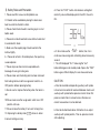
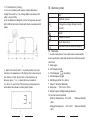
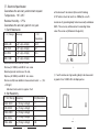
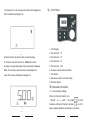
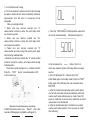
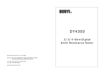
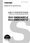
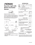
DY4300
4 WIRES DIGITAL EARTH RESISTANCE
Ⅷ. Replacing Battery
a. Do not open the battery cover if the outer casing is wet.
b. Do not replace the battery during test. Please turn the
range switch to “OFF" and remove testing leads,earth
Ⅰ. General Introduction ¼
¼
¼
¼
¼
¼
¼
¼
¼
¼
¼
…¼
1
Ⅱ. Safety Rules and Precaution¼
¼
¼
¼
¼
¼
¼
.¼
¼
2
Ⅲ. Electrical symbol ¼
¼
¼
¼
¼
¼
¼
¼
¼
¼
¼
.¼
¼
¼
3
Ⅳ. Features ¼
¼
¼
¼
¼
¼
¼
¼
¼
¼
¼
¼
¼
¼
¼
¼
¼
¼
3
spikes,et c before replacing the battery to aviod electic
Ⅴ. Electrical Specification¼
¼
¼
¼
¼
¼
¼
¼
¼
¼
¼
¼
4
shock.
Ⅵ. Front Panel ¼
¼
¼
¼
¼
¼
¼
¼
¼
¼
..¼
¼
¼
¼
¼
¼
5
Ⅶ. Operation Instruction ¼
¼
¼
¼
¼
¼
¼
¼
¼
¼
¼
¼
¼
5
c. Undo the screw on battery cover at the bottom of the
unit and open the battery cover.
d. Put into new batteries,then put battery cover back and
Ⅷ. Replacing Battery ¼
¼
¼
¼
¼
¼
¼
¼
¼
¼
.¼
¼
¼
¼
12
Ⅸ. Accessories¼
¼
¼
¼
¼
¼
¼
¼
¼
¼
¼
¼
¼
¼
¼
¼
¼
12
tighten the screw.
CAUTION
Ⅸ. Accessories
a. Four auxiliary earth spikes
b. Testing Wires(Inc luding Red testing wire 15 meters
each,Yellow testing wire 10 meters each,Green testing
wire 5 meters each, Black testing wire 5 meters each)
c. 1.5V(AA) Battery 4 pcs
d. Instrucation Manual
e. Tool Box
f. Tool Bag
12
This user manual includes warning and safety
specifications,which shall be strictly followed to
ensure safety.Please be sure to read through this
user manual before using this instrument.
Ⅰ.
General Introduction
DY4300 Digital Earth Resistance Tester is a new
genera tion tes ter for e le ct ric ia n pra ct ice which is
de velope d by ou r compan y in rec ent y ea rs. The
circu it ,s truct ure and t ec hnique of traditional e arth
resistance tester have been improved and new design is
both f ine-lo oking a nd pract ical. Th is one has more
complete functions,higher accuracy,more convenient and
reliable for operation and more suitable for outdoor use
with du st and wet proof st ructure. It can tes t earth
resistance of various earth systems including power
systems,electric equiments,lightning conductors as well
as earth resistivit y (ρ) Measurement.
1
Ⅱ. Safety Rules and Precaution
d. Press the “TEST” button after distance setting,Soil
1. Please read this manual carefully before use.
resistivity value will be displayed on the LCD ,the unit is
2.It should not be used before placing the back cover
Ωm.
back to avoid risk of electric shock.
3. Please check the test leads's insu lating layer is intact
before used.
4. Please do not touch lead terminal and dircuit under test
to avoid electric shock.
10
5. Make sure the coupler plug of lead inserted in the
terminal tightly.
e. If do not release the ‘TEST’ button, then it is in
6.Please do not test in flammable place, the spark may
continuous measuring state, refreshing about once every
second.
cause explosion
f. The LCD displayed "OL" if releas ing the "test"
7. Please stop use when metal is exposed due to
breakage of casing or testing wire.
button,Meter goes into standby mode.If press the "TEST"
button again,LCD will display the new measured value.
8. Please make sure the testing wire has been removed
from testing terminal and the range select switch is on
CAUTION
OFF position before replacing battery.
a. Must be inserted corresponding auxiliary earth spikes
9. Do not use it or replace the battery when the tester is
into soil and connected all leads well between meter and
auxiliary earth spikes before power on meter. Never first
wet.
10.Please make sure the range select switch is on OFF
position after use.
power on meter then to connect wires, otherwise no
correct measurement can be obtained.
11.Please remove the battery if not use it for long time .
b. Must be shutted meter down first before to re-adjust
12. Replacing the battery when
auxiliary earth spikes pos ition, Then re-power on meter
shown on tester
after adjusting.
to ensure testing accuracy.
2
11
7-3 Soil Resistivity Testing
a. Line up 4 auxiliary earth spikes at equal distance in
straight line called ‘a’ (m), driving depth of auxiliary earth
spike is about 1/20a.
b. As the Reference Diagram 8, Four testing wires connect
E,S,H,ES test terminal of meter with the four auxiliary earth
spikes.
Ⅲ. Electrical symbol
~
AC
Refer to manual
Dangerous voltage (Danger! electric
shock!)
Earth
Double insulation
Ω
Earth Resistance
Low battery when shown on display
Ⅳ. Features
88
c. Set the functional switch to ρearth position, then the
instrument is powered on, LCD display after a few seconds
was shown in Fig.9; where, 10m is the previously set
distance, press ↑or↓to reset distance (variable in
1m-30m, 1m each time). This distance must be equal to
actual distance between auxiliary earth spikes.
1. 4 wires measurement can avoid 3 wires measurement
error caused by E-pole lead resistance and clamp contact
resistance;
2. Auto range;
3. LCD Display:4 Digit
4. LCD displayed
low battery
5. LCD Background Light
6. LED Display Size: 65×48mm
7. Power:1.5V(AA)x4 Batteries
8. Dimension: 190×155×75mm
9. Weight: approx. 900g(including batteries)
10. Environmental Condition
Working Temperature 0℃- 40℃
Relative Humidity
<80%
Storage Temperature -10℃-50℃ Relative Humidity
<85%
9
10
3
Ⅴ. Electrical Specification
Guarantees the accuracy environment request:
Temperature:18℃-28℃
Relative Humidity:<75%
Guarantees the accuracy period: one year.
1. Earth Resistance
(Ω)Range
Accuracy
e. Maximal earth resistance Rpmax which belong
to“S”terminal must be less than 100Re(Re = Earth
resistance of grounding body to be measured) and below
50kΩ, The accuracy will be worse if exceeding these
value.The value as (Reference Diagram 6)
(Ω)
Resolution
0.00~6.99
±(3% dgt +6 Digit)
0.01
7.0~49.9
±(2% dgt +3 Digit)
0.1
50~ 299.5
±(2% dgt +3 Digit)
0.5
300~1500
±(2% dgt +3 Digit)
1
Maximal earth resistance at H-end :
Rcmax=(0-100Re) and 50KΩ less value
69
Maximal ground resistance at S- end:
Rpmax=(0-100Re) and 50KΩ less value
f、If earth resistance of grounding body to be measured
Rcmax and Rpmax additional measurement error: ±(3%
is greater than 1500Ω,LCD will displayed as
+10 Digit)
Maximum test current is approx. 2mA
2. Soil Resistivity
(Ωm)Range
Accuracy
(Ωm)Resolution
0.00~99.99
±(3% dgt + 6 Digit)
0.1
100~999.9
±(2% dgt + 3 Digit)
0.1
1000~9999
±(2% dgt + 3 Digit)
1
10k~99.9k
±(2% dgt + 3 Digit)
10
100k~300k
±(2% dgt + 3 Digit)
100
4
97
9
c. Instrument can not measure when the earth voltage over
Ⅵ、Front Panel
20V as (Reference Diagram 4)
1. LCD Display
49
2. Test terminal‘S’
d. Maximal earth resistance Rcmax which belong
3. Test terminal‘E’
to“H”terminal must be less than 100Re(Re = Earth
4. Test terminal‘H’
resistance of grounding body to be measured) and below
5. Test terminal‘ES’
50kΩ, The accuracy will be worse if exceeding these
6. Increases spikes distance button
value.The value as (Reference Diagram 5)
7. Test button
8. Decreases spikes d istance button
9. Function Switch
Ⅶ. Operation Instruction
7-1. Check battery voltage
When the Function Switch is on
95
8
‘Rearth’ or‘ρ earth’ , no symbol
on LCD
indicates sufficient 6V battery .Symbol
on LCD,
please replace batteries ac cording to instruction.
5
7-2. Earth Resistance Testing
a. Prior to measurement, please ensure that test wire plug
has been inserted into test socket completely, otherwise,
measurement error will occur or measuring will be
impossible.
Wires connecting method:
1 .Black
○
wire one terminal inserted into "E"
socket,another termminal clamp the earth body wh ich
want to be measured.
2 .Green
○
wire one terminal inserted into "Es"
socket,another termminal clamp the earth body wh ich
want to be measured too.
3 .Yellow
○
wire one terminal inserted into "S"
socket,another termminal clamp the auxiliary earth sp ike
which locating middle position.
4 .Red wire one terminal inserted into "H" socket,another
○
termminal clamp the auxiliary earth spike which locating
farthest position.
The function switch setting on R EA RTH, it will be s how 0Ω
Press the ‘TEST’ button, Value displayed on LCD
is earth resistance.
Black
Green
Red
Yel
low
2
c. Press the ‘TEST’button,LCD displayed the value which
want to be measured object. (Reference Diagram 3)
3
d. Do not release the ‘TEST’ button, then it is in
continuous measuring state, refreshing about once every
second.
e.The LCD displayed "OL" if releasing the "test"
button,Meter goes into standby mode.If press the "TEST"
button again,LCD will display the new measured value.
ÿ
NOTICE
b.When the function switch is on ‘Rearth’, after a few
seconds LCD displayed as (Reference Diagram 2)
a. Must be inserted corresponding auxiliary earth spikes
into soil and connected all leads well between meter and
auxiliary earth spikes before power on meter. Never first
power on meter then to connect wires, otherwise no correct
measurement can be obtained.
b. Must be shutted meter down first before to re-adjust
auxiliary earth spikes position, Then re-power on meter
after adjusting.
6
7
1
◆Example of recommended measuring methods