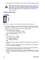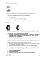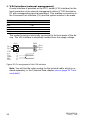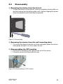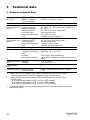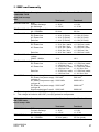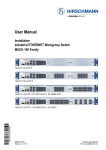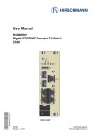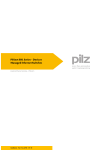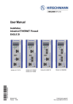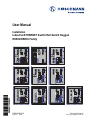
1
User Manual Installation Industrial ETHERNET Switch Rail Switch Rugged RSR20/RSR30 Family 5 6 7 8 9 10 3 4 3 4 5 6 5 6 5 6 7 8 7 8 7 8 9 10 9 10 9 10 1 2 RSR20/RSR30 Release 03/08 3 4 3 4 5 6 5 6 7 8 7 8 Technical Support [email protected] The naming of copyrighted trademarks in this manual, even when not specially indicated, should not be taken to mean that these names may be considered as free in the sense of the trademark and tradename protection law and hence that they may be freely used by anyone. © 2008 Hirschmann Automation and Control GmbH Manuals and software are protected by copyright. All rights reserved. The copying, reproduction, translation, conversion into any electronic medium or machine scannable form is not permitted, either in whole or in part. An exception is the preparation of a backup copy of the software for your own use. For devices with embedded software, the end-user license agreement on the enclosed CD applies. The performance features described here are binding only if they have been expressly guaranteed in the contract. This publication has been created by Hirschmann Automation and Control GmbH according to the best of our knowledge. Hirschmann reserves the right to change the contents of this manual without prior notice. Hirschmann can give no guarantee in respect of the correctness or accuracy of the details in this publication. Hirschmann can accept no responsibility for damages, resulting from the use of the network components or the associated operating software. In addition, we refer to the conditions of use specified in the license contract. Printed in Germany Hirschmann Automation and Control GmbH Stuttgarter Str. 45-51 72654 Neckartenzlingen Germany Tel.: +49 1805 141538 039 698-001-02-0308 – 13.3.08 Contents Safety instructions 4 About this manual 9 Legend 9 1 Device description 10 1.1 Description of the device variants 1.1.1 Combination options RSR20/RSR30 1.1.2 Port number and media for RSR20-... 1.1.3 Port number and media for RSR30-... 11 12 15 18 2 Assembly and start-up 22 2.1 Installing the device 22 2.1.1 Unpacking and checking 22 2.1.2 Installing the SFP modules 22 2.1.3 Installing the device and grounding 23 2.1.4 Connecting the terminal blocks for supply voltage and signal contact 25 2.1.5 Installing the terminal blocks; start-up procedure 28 2.1.6 Installing the data lines 29 2.2 Display elements 31 2.3 Making basic settings 33 2.4 Disassembly 35 3 Technical data 36 RSR20/RSR30 Release 03/08 3 Safety instructions This documentation contains instructions which must be observed to ensure your own personal safety and to avoid damage to devices and machinery. Certified usage The device may only be employed for the purposes described in the catalog and technical description, and only in conjunction with external devices and components recommended or approved by the manufacturer. The product can only be operated correctly and safely if it is transported, stored, installed and assembled properly and correctly. Furthermore, it must be operated and serviced carefully. Supply voltage The supply voltage is electrically isolated from the housing. Use only undamaged parts! The device does not contain any service components. Internal fuses only trigger if there is a fault in the device. If the device is not functioning correctly, or if it is damaged, switch off the voltage supply and return the device to the plant for inspection. Only switch on the supply voltage to the device if - the housing is closed, - the terminal blocks are wired up correctly and - the terminal blocks are connected for the voltage supply. Connect the protective conductor with the ground screw before you set up the other connections. When removing the connections, you remove the protective conductor last. Make sure that the cross-section of the protective conductor cable is the same size as or bigger than the cross-section of the voltage supply cables. Only use connection cables that are permitted for the specified temperature range. WARNING: - If the neutral conductor or the negative terminal of the supply voltage is not grounded - If you are using a DC voltage greater than 125 VDC for the supply voltage install a suitable input fuse. For power supply units with product code "K", use a slow-blow fuse with a nominal rating of 2.5 A for the voltage supply input. For power supply units with product code "C", use a slow-blow fuse with a nominal rating of 6.3 A. With AC power supply, use a cable cross-section of at least 0.75 mm² 4 RSR20/RSR30 Release 03/08 (for North America AWG 18) for the current conductor at the voltage input. With DC power supply, use a cable cross-section of at least 1.0 mm² (for North America AWG 16) for the current conductor at the voltage input. Relevant for North America: Only use copper wire/conductors of class 1 105°C. Note: Only connect a supply voltage that corresponds to the type plate of your device. Power supply type "C": 24 to 48 V DC Power supply type "K": 60 to 250 V DC or 110 to 230 V AC Shielding ground The shielding ground of the connectable twisted pairs lines is connected to the front panel as a conductor. Beware of possible short circuits when connecting a cable section with conductive shielding braiding. Housing Only technicians authorized by Hirschmann are permitted to open the housing. The device is grounded via the separate ground screw. It is located on the bottom left of the front panel. Make sure that the electrical installation meets local or nationally applicable safety regulations. The ventilation slits must not be covered to ensure free air circulation. The distance to the ventilation slots of the housing has to be a minimum of 10 cm. For devices with temperature range "U" or "F", the distance to the next device must be at least 2 cm. Never insert pointed objects (thin screwdrivers, wires, etc.) into the inside of the subrack! Failure to observe this point may result in injuries caused by electric shocks. The device must be installed in the vertical position. If installed in a living area or office environment, the device must be operated exclusively in switch cabinets with fire protection characteristics according to EN 60950. Environment The device may only be operated in the listed maximum surrounding air temperature range at the listed relative air humidity range (non-condensing). The installation location is to be selected so as to ensure compliance with the climatic limits listed in the Technical Data. To be used in a Pollution Degree listed in the Technical Data. RSR20/RSR30 Release 03/08 5 Qualification requirements for personnel Qualified personnel as understood in this manual and the warning signs, are persons who are familiar with the setup, assembly, startup, and operation of this product and are appropriately qualified for their job. This includes, for example, those persons who have been: X trained or directed or authorized to switch on and off, to ground and to label power circuits and devices or systems in accordance with current safety engineering standards; X trained or directed in the care and use of appropriate safety equipment in accordance with the current standards of safety engineering; X trained in providing first aid. General safety instructions This device is electrically operated. Adhere strictly to the safety requirements relating to voltages applied to the device as described in the operating instructions! Failure to observe the information given in the warnings could result in serious injury and/or major damage. Only personnel that have received appropriate training should operate this device or work in its immediate vicinity. The personnel must be fully familiar with all of the warnings and maintenance measures in these operating instructions. Correct transport, storage, and assembly as well as careful operation and maintenance are essential in ensuring safe and reliable operation of this device. Only use undamaged parts! These products are only to be used in the manner indicated in this version of the manual. Particular attention is to be paid to all warnings and items of information relating to safety. Any work that may have to be performed on the electrical installation should be performed by fully qualified technicians only. Warning! LED- or LASER components according to IEC 60825-1 (2001): CLASS 1 LASER PRODUCT. LIGHT EMITTING DIODE - CLASS 1 LED PRODUCT. Warning Laser light Do not look into the beam or view it directly with optical instruments (e.g. magnifying glasses, microscopes). Failure to observe this warning within a distance of 100 mm 6 RSR20/RSR30 Release 03/08 can endanger your sight. Light is emitted from the optical connections or from the ends of the optical fibers that are connected to them. Light Emitting Diode CLASS 2M, wave length 650 nm, power <2 mW, according to DIN EN 60825-1:2003-10. National and international safety regulations Make sure that the electrical installation meets local or nationally applicable safety regulations. Note on the CE marking The devices comply with the regulations contained in the following European directives: 89/336/EEC Directive of the council for standardizing the regulations of member states on electromagnetic compatibility (changed by RL 91/263/EEC, 92/31/ EEC and 93/68/EEC). In accordance with the above-named EU directives, the EU conformity declaration will be at the disposal of the relevant authorities at the following address: Hirschmann Automation and Control GmbH Stuttgarter Str. 45-51 72654 Neckartenzlingen Tel.: +49 1805 141538 The product can be used in living areas (living area, place of business, small business) and in industrial areas. X Interference immunity: EN 61000-6-2:2001 X Emitted interference: EN 55022:1998 + A1 2000 + A2 2003 Class A Warning! This is a class A device. This device can cause interference in living areas, and in this case the operator may be required to take appropriate measures. The assembly guidelines provided in these instructions must be strictly adhered to in order to observe the EMC value limits. RSR20/RSR30 Release 03/08 7 FCC note Appropriate testing has established that this device fulfills the requirements of a class A digital device in line with part 15 of the FCC regulations. These requirements are designed to provide sufficient protection against interference where the device is being used in a business environment. The device creates and uses high frequencies and can radiate same, and if it is not installed and used in accordance with this operating manual, it can cause radio transmission interference. The use of this device in a living area can also cause interference, and in this case the user is obliged to cover the costs of removing the interference. Recycling note After usage, this product must be disposed of properly as electronic waste in accordance with the current disposal regulations of your county / state / country. 8 RSR20/RSR30 Release 03/08 About this manual The following manuals are available as PDF files on the CD-ROM supplied: X X X X X X "Installation" user manual "Basic Configuration" user manual "Redundancy Configuration" user manual "Industry Protocols" user manual "Web-based Interface" user manual and "Command Line Interface" user manual The Network Management Software HiVision provides you with additional options for smooth configuration and monitoring: X X X X X X Event logbook. Configuration of „System Location“ and „System Name“. Configuration of the network address range and SNMP parameters. Saving the configuration on the device. Simultaneous configuration of multiple devices. Configuration of the port display color red for a connection error. Legend The commendations used in this manual have the following meanings: X Listing Work step Subheading RSR20/RSR30 Release 03/08 9 1 Device description The Rail Switch Rugged RSR20/RSR30 series provides you with a range of Switch variants. You set up your own Switch according to your requirements regarding the number of ports, transmission speed, media type, connector type, temperature range, certifications and software variant. The devices are designed for the special requirements of industrial automation. They meet the relevant industry standards, provide very high operational reliability, even under extreme conditions, and also long-term reliability and flexibility. The devices operate without fans and have a redundant voltage supply. The Switches are mounted very quickly by snapping them onto a hat rail, or by mounting them on a wall. The HIPER-Ring redundancy concept enables you to quickly carry out a reconfiguration, and also a simple configuration with only one additional connection. The diagnosis display and the display of the operating parameters and IP address information field provide a quick overview. It can be easily managed via a Web browser, via Telnet, via SSH, with a management software product (such as HiVision) or locally on the Switch (V.24 interface). The devices allow you to set up switched industrial ETHERNET networks that conform to the IEEE 802.3 and 802.3u standards using copper wires or optical fibers in a line or ring structure. You can connect terminal devices and other infrastructure components via twisted pair cables, multi-mode LWL and single-mode LWL. The twisted pair ports support autocrossing, autonegotiation and autopolarity. Depending on the software you choose, the devices provide you with a large range of functions: X Redundancy functions (Rapid Spanning Tree, Redundant Ring Structure, HIPER-Ring, Redundant Coupling, Link Aggregation, Redundant Power Supply) X Protection from unauthorized access X Synchronization of system time in the network (SNTP, PTP) X Network load control and limitation X Network filter X Operation diagnosis X Diagnostics (hardware self-testing) X Reset X Priority X VLAN X Topology discovery X Web-based Interface 10 RSR20/RSR30 Release 03/08 X X X X Command Line Interface CLI SNMP 802.1x port authentication Real Time Clock (Professional software variant) The addition to the Open Rail Rugged RS20/RS30 series of the Open Rail RS20/RS30/RS40 series, the Switches of the MICE series, the MACH series of backbone Switches, the BAT wireless transmission system, the EAGLE security system, and products for the LION control room, provides continuous communication across all levels of the company. 1.1 Description of the device variants The devices differ with regard to the range of software functions, the number of interfaces, and the media type for connecting segments. X The RSR30-... device variants are Rail Switches Rugged with 2 to 3 gigabit Ethernet ports (1000 Mbit/s) and six to eight 10/100 Mbit/s Ethernet ports. X The RSR20-... device variants are Rail Switches Rugged without gigabit Ethernet ports and eight to nine 10/100 Mbit/s Ethernet ports. The devices also provide you with the following options for selecting the variant you desire: X Temperature range: X Standard (0°C to 60°C) X Extended (-40°C to +85 °C) without conformal coating X Extended (-40°C to +85 °C) with conformal coating X Voltage ranges for power supply unit 1 and the optional power supply unit 2 (inclusive maximum tolerances): X 18 VDC to 60 VDC X 48 VDC to 320 VDC or 90 VAC to 265 VAC X Certifications /declarations: X CE; UL508; Germanischer Lloyd GL; IEC/EN 61850-3 declaration (substation); IEEE 1613 substation; EN 50121-4 railway (along track) X CE; UL508; Germanischer Lloyd GL; IEC/EN 61850-3 declaration (substation); IEEE 1613 substation; EN 50121-4 railway (along track), EN 50155 X Software variant: Professional RSR20/RSR30 Release 03/08 11 The devices comply with the specifications of the ISO/IEC standards 8802-3u 100BASE-TX/-1000BASE-T, 8802-3 100BASE-FX and 8802-3 1000BASE-SX/LX. 1.1.1 Combination options RSR20/RSR30 The product designation of your MS20/MS30 device is made from combining the desired product characteristics in accordance with the following table. The short designation is in column 3. 12 RSR20/RSR30 Release 03/08 Item Characteristic feature Characteristic value 1 to 5 Product RSR20 RSR30 6 - (hyphen) 7 to 8 Number of 100 Mbit/s 06 ports 07 08 09 9 and 10 Number of 1000 Mbit/ 00 s ports 02 03 11 and 12 Port 1 and 2 or port 1 CC OO MM JJ NN VV UU LL GG O7 O6 T1 M2 M3 M4 S2 S4 L2 G2 13 and 14 Port 2 or port 3 and ZZ port 3 and 4 O7 O6 T1 M2 M3 M4 S2 S4 L2 G2 Property Rail Switch Rugged without gigabit ports Rail Switch Rugged with gigabit ports 6 * 100 Mbit/s Ethernet 7 * 100 Mbit/s Ethernet 8 * 100 Mbit/s Ethernet 9 * 100 Mbit/s Ethernet 0 * 1000 Mbit/s Ethernet 2 * 1000 Mbit/s Ethernet 3 * 1000 Mbit/s Ethernet 2 * Combo port 1000 Mbit/s Ethernet 2 * SFP slots 1000 Mbit/s Ethernet 2 * Multimode FX (DSC) 2 * Multimode FX (MTRJ) 2 * Multimode FX (ST) 2 * Singlemode FX (DSC) 2 * Singlemode FX (ST) 2 * Singlemode Long Haul FX (DSC) 2 * Singlemode Long Haul FX (DSC) 200 km 1 * Combo port 1000 Mbit/s Ethernet 1 * SFP slots 1000 Mbit/s Ethernet 1 * Twisted Pair TX (RJ45) 1 * Multimode FX (DSC) 1 * Multimode FX (MTRJ) 1 * Multimode FX (ST) 1 * Singlemode FX (DSC) 1 * Singlemode FX (ST) 1 * Singlemode Long Haul FX (DSC) 1 * Singlemode Long Haul FX (DSC) 200 km 2 * SFP slots (only 100 Mbit/s) 1 * Combo port 1000 Mbit/s Ethernet 1 * SFP slots 1000 Mbit/s Ethernet 1 * Twisted Pair TX (RJ45) 1 * Multimode FX (DSC) 1 * Multimode FX (MTRJ) 1 * Multimode FX (ST) 1 * Singlemode FX (DSC) 1 * Singlemode FX (ST) 1 * Singlemode Long Haul FX (DSC) 1 * Singlemode Long Haul FX (DSC) 200 km Table 1: Combination options for the device variants of RSR20/RSR30 RSR20/RSR30 Release 03/08 13 Item Characteristic feature Characteristic value 15 and 16 Remaining ports T1 Z6 17 Temperature range S U F 18 Voltage range 1 incl. C maximum tolerances K 19 Voltage range 2 incl. 9 maximum tolerances C K 20 Certifications H C 21 Software feature ver- P sion Property Twisted Pair TX (RJ45) SFP slot (only 100 Mbit/s) Standard 0 °C to 60 °C Extended -40 °C to 85 °C Extended -40 °C to 85 °C and conformal coating 18 VDC ... 60 VDC 48 VDC ... 320 VDC or 90 VAC ... 265 VAC Not available 18 VDC ... 60 VDC 48 VDC ... 320 VDC or 90 VAC ... 265 VAC CE; UL508; GL; IEC61850; IEEE 1613 substation; EN 50121-4 railway (along track) CE; UL508; GL; IEC61850; IEEE 1613 substation; EN 50121-4 railway (along track); EN50155 Professional Table 1: Combination options for the device variants of RSR20/RSR30 Examples for product name Example: RSR20-0900... RSR20-: Rail Switch Rugged without gigabit ports 09: 9 x 100 Mbit/s Ethernet ports 00: 0 x 1000 Mbit/s Ethernet ports MM: Port 1 + 2 = 2 x multimode FX (DSC) S2: Port 3 = 1 x singlemode FX (DSC) T1: Further 6 ports = twisted pair TX (RJ45) F: Temperature range: extended (-40 °C to +85 °C), conformal coating K: Voltage range 1 = 48V ... 320 VDC or 90V ... 265 VAC C: Voltage range 2 = 18V ... 60 VDC H: Specifications: CE; UL508; GL; IEC61850; IEEE 1613 substation; EN 50121-4 railway (along track) P: Software variant: professional RSR20-09 00 MM S2 T1 F K C H P 14 RSR20/RSR30 Release 03/08 1.1.2 Port number and media for RSR20-... To put together your personal RSR20 device in the above table (see table 1), you have the following combination options ("?" = any value from the "Characteristic value" column): Position 1 to 10 RSR20-0900 Position 11 to 12 JJ Position 13 to 14 M3 Position 15 to 16 T1 Position 17 ? Position 18 to 19 KK K9 KC CC KK K9 KC CC Position 20 to 21 ?P -“- MM -“- -“- -“-“-“-“-“- NN VV UU LL GG M2 M4 S2 S4 L2 G2 -“-“-“-“-“- -“-“-“-“-“- -“-“-“-“-“- -“-“-“-“-“- -“-“-“-“-“- Position 18 to 19 KK K9 KC CC KK K9 KC CC Position 20 to 21 ?P -“-“-“-“-“- -“-“-“-“-“- -“- Table 2: Combination options for RSR20-0900... Position 1 to 10 RSR20-0800 Position 11 to 12 T1 Position 13 to 14 T1 Position 15 to 16 T1 Position 17 ? -“- M2 -“- -“- -“-“-“-“-“- M2 S2 S4 L2 G2 M2 M4 S2 S4 L2 G2 -“-“-“-“-“- -“-“-“-“-“- -“-“-“-“-“- -“- Table 3: Combination options for RSR20-0800... RSR20/RSR30 Release 03/08 15 LED display elements port state LED display elements device state Voltage range 1, at your option (product code position 18) C = 18V ... 60VDC K = 48V ... 320 VDC or 90V ... 265 VAC Port 1 to 3: 3 x 100 Mbit/s fiber optic DSC/DST USB interface Signal contact 1 V.24 access external management 4 5 Voltage range 2, at your option (product code position 19) 9 = not assembled C = 18V ... 60VDC K = 48V ... 320 VDC or 90V ... 265 VAC 6 7 Signal contact 2 8 9 Port 4 to 9: 6 ports in line with 10/100BASE-T(X) (RJ45 connectors) Figure 1: RSR20 device variants with 3 F/O ports (DSC) and 6 TX ports (RJ45) LED display elements port state LED display elements device state Voltage range 1, at your option (product code position 18) C = 18V ... 60VDC K = 48V ... 320 VDC or 90V ... 265 VAC USB interface Signal contact 1 V.24 access external management Port 1 to 2: 2 x 100 Mbit/s fiber optic DSC/DST 3 4 Voltage range 2, at your option (product code position 19) 9 = not assembled C = 18V ... 60VDC K = 48V ... 320 VDC or 90V ... 265 VAC 5 6 Signal contact 2 7 8 Port 3 to 8: 6 ports in line with 10/100BASE-T(X) (RJ45 connectors) Figure 2: RSR20 device variants with 2 F/O ports (DSC) and 6 TX ports (RJ45) 16 RSR20/RSR30 Release 03/08 LED display elements port state LED display elements device state Voltage range 1, at your option (product code position 18) C = 18V ... 60VDC K = 48V ... 320 VDC or 90V ... 265 VAC USB interface Signal contact 1 V.24 access external management 1 2 3 4 Voltage range 2, at your option (product code position 19) 9 = not assembled C = 18V ... 60VDC K = 48V ... 320 VDC or 90V ... 265 VAC 5 6 Signal contact 2 7 8 Port 1 to 8: 8 ports in line with 10/100BASE-T(X) (RJ45 connectors) Figure 3: RSR20 device variants with 8 TX ports (RJ45) LED display elements port state LED display elements device state Voltage range 1, at your option (product code position 18) C = 18V ... 60VDC K = 48V ... 320 VDC or 90V ... 265 VAC Port 1 to 3: 3 x 100 Mbit/s fiber optic MTRJ MM USB interface Signal contact 1 V.24 access external management 4 5 Voltage range 2, at your option (product code position 19) 9 = not assembled C = 18V ... 60VDC K = 48V ... 320 VDC or 90V ... 265 VAC 6 7 Signal contact 2 8 9 Port 4 to 9: 6 ports in line with 10/100BASE-T(X) (RJ45 connectors) Figure 4: RSR20 device variants with 3 F/O ports (MTRJ) and 6 TX ports (RJ45) RSR20/RSR30 Release 03/08 17 1.1.3 Port number and media for RSR30-... To put together your personal RSR30 device in the above table (see table 1), you have the following combination options ("?" = any value from the "Characteristic value" column): Position 1 to 10 RSR30-0603 Position 11 to 12 CC Position 13 to 14 O7 Position 15 to 16 T1 Position 17 ? Position 18 to 19 KK K9 KC CC Position 20 to 21 ?P Position 20 to 21 ?P -“-“-“- Position 20 to 21 ?P Table 4: Combination options for RSR30-0603... Position 1 to 10 RSR30-0802 Position 11 to 12 CC Position 13 to 14 ZZ Position 15 to 16 T1 Position 17 ? -“-“-“- O7 OO O6 O7 ZZ O6 -“-“-“- -“-“-“- Position 18 to 19 KK K9 KC CC -“-“-“- Position 17 ? Position 18 to 19 K9 Table 5: Combination options for RSR30-0802... Position 1 to 10 RSR30-0703 Position 11 to 12 OO Position 13 to 14 ZZ Position 15 to 16 Z6 Table 6: Combination options for RSR30-0703... For device variants with combo ports (fiber optic SFP slot as alternative to RJ45 connection), the following applies: X SFP slots: 100/1000Mbit/s X RJ45 connection: 10/100/1000MBit/s 18 RSR20/RSR30 Release 03/08 LED display elements port state LED display elements device state Voltage range 1, at your option (product code position 18) C = 18V ... 60VDC K = 48V ... 320 VDC or 90V ... 265 VAC Port 1 to 3: 3 x 10/100/ 1000 Mbit/s combo ports (fiber optic SFP slot and RJ45 connector) USB interface Signal contact 1 V.24 access external management 4 5 Voltage range 2, at your option (product code position 19) 9 = not assembled C = 18V ... 60VDC K = 48V ... 320 VDC or 90V ... 265 VAC 6 7 Signal contact 2 8 9 Port 4 to 9: 6 ports in line with 10/100BASE-T(X) (RJ45 connectors) Figure 5: RSR30 device variants with 3 combo ports and 6 TX ports (RJ45) LED display elements port state Port 1 to 3: 3 x 1000 Mbit/s fiber optic SFP slot LED display elements device state Voltage range 1, at your option (product code position 18) C = 18V ... 60VDC K = 48V ... 320 VDC or 90V ... 265 VAC USB interface Signal contact 1 Port 4 to 10: 7 x 100 Mbit/s fiber optic SFP slot V.24 access external management Voltage range 2, at your option (product code position 19) 9 = not assembled C = 18V ... 60VDC K = 48V ... 320 VDC or 90V ... 265 VAC Signal contact 2 Figure 6: RSR30 device variants with 7 plus 3 SFP slots (100 and 1000 Mbit/s) RSR20/RSR30 Release 03/08 19 LED display elements port state LED display elements device state Voltage range 1, at your option (product code position 18) C = 18V ... 60VDC K = 48V ... 320 VDC or 90V ... 265 VAC Port 1 to 2: 2 x 10/100/ 1000 Mbit/s combo ports (fiber optic SFP slot and RJ45 connector) USB interface Signal contact 1 V.24 access external management 5 6 Port 3 to 4: 2 x 100 Mbit/s fiber optic SFP slot Voltage range 2, at your option (product code position 19) 9 = not assembled C = 18V ... 60VDC K = 48V ... 320 VDC or 90V ... 265 VAC 7 8 Signal contact 2 9 10 Port 5 to 10: 6 ports in line with 10/100BASE-T(X) (RJ45 connectors) Figure 7: RSR30 device variants with 2 combo ports, 2 SFP slots and 6 TX ports (RJ45) LED display elements port state LED display elements device state Voltage range 1, at your option (product code position 18) C = 18V ... 60VDC K = 48V ... 320 VDC or 90V ... 265 VAC Port 1 to 2: 2 x 1000 Mbit/s fiber optic SFP slot USB interface Signal contact 1 V.24 access external management 5 6 Port 3 to 4: 2 x 100 Mbit/s fiber optic SFP slot Voltage range 2, at your option (product code position 19) 9 = not assembled C = 18V ... 60VDC K = 48V ... 320 VDC or 90V ... 265 VAC 7 8 Signal contact 2 9 10 Port 5 to 10: 6 ports in line with 10/100BASE-T(X) (RJ45 connectors) Figure 8: RSR30 device variants with 2 plus 2 SFP slots (100 and 1000 Mbit/s) and 6 TX ports (RJ45) 20 RSR20/RSR30 Release 03/08 LED display elements port state LED display elements device state Voltage range 1, at your option (product code position 18) C = 18V ... 60VDC K = 48V ... 320 VDC or 90V ... 265 VAC Port 1 to 2: 2 x 10/100/ 1000 Mbit/s combo ports (fiber optic SFP slot and RJ45 connector) USB interface Signal contact 1 V.24 access external management Voltage range 2, at your option (product code position 19) 9 = not assembled C = 18V ... 60VDC K = 48V ... 320 VDC or 90V ... 265 VAC 3 4 5 6 7 8 Signal contact 2 9 10 Port 3 to 10: 8 ports in line with 10/100BASE-T(X) (RJ45 connectors) Figure 9: RSR30 device variants with 2 combo ports and 8 TX ports (RJ45) LED display elements port state LED display elements device state Voltage range 1, at your option (product code position 18) C = 18V ... 60VDC K = 48V ... 320 VDC or 90V ... 265 VAC Port 1 to 2: 2 x 1000 Mbit/s fiber optic SFP slot USB interface Signal contact 1 V.24 access external management 3 4 5 6 Voltage range 2, at your option (product code position 19) 9 = not assembled C = 18V ... 60VDC K = 48V ... 320 VDC or 90V ... 265 VAC 7 8 Signal contact 2 9 10 Port 3 to 10: 8 ports in line with 10/100BASE-T(X) (RJ45 connectors) Figure 10: RSR30 device variants with 2 SFP slots and 8 TX ports (RJ45) RSR20/RSR30 Release 03/08 21 2 Assembly and start-up The devices have been developed for practical application in a harsh industrial environment. The installation process is correspondingly simple. On delivery, the device is ready for operation. The following procedure has been proven to be successful for the assembly of the device: X X X X Unpacking and checking Installing the SFP modules Installing the device and grounding Connecting the terminal blocks for voltage supply and signal contact and connecting the supply voltage X Installing the terminal blocks; start-up procedure X Installing the data lines 2.1 Installing the device 2.1.1 Unpacking and checking Check whether the contents of the package are complete (see page 40 "Scope of delivery"). Check the individual parts for transport damage. 2.1.2 Installing the SFP modules Fast ETHERNET Fiberoptic SFP module Gigabit ETHERNET Fiberoptic SFP module Figure 11: Installing an SFP module To attach an SFP module, first remove the protective cap over the socket. Push the SFP module with the lock closed into the socket until it latches audibly in place. Note: Only use Hirschmann SFP modules. 22 RSR20/RSR30 Release 03/08 2.1.3 Installing the device and grounding You can mount the device on the hat rail or mount it on the wall using the wall mounting plate supplied (see on page 40 "Accessories"). Mounting on the hat rail Figure 12: Mounting the RSR20/RSR30 on the hat rail Mount the device on a 35 mm hat rail in accordance with DIN EN 60175. Attach the upper snap-in guide of the device into the hat rail and press it down against the hat rail until it snaps into place. Note: The shielding ground of the industrial connectable twisted pair lines is connected to the lower panel as a conductor. RSR20/RSR30 Release 03/08 23 Wall mounting Figure 13: Mounting the RSR20/RSR30 on the wall Fasten on the wall mounting plate (width 120 mm) (see on page 40 "Accessories") on a level wall surface using four screws. Mount the device on the wall plate as shown in the illustration. Attach the upper snap-in guide of the device into the rail and press it down against the rail until it snaps into place. Grounding The device is grounded via the separate ground screw on the front panel of the device. The devices have a protective conductor connection. Connect the protective conductor to the ground screw of the device. Connect the protective conductor before you set up the other connections. When removing the connections, you remove the protective conductor last. Connect both protective conductors if your device is equipped with two power supply units. 24 RSR20/RSR30 Release 03/08 2.1.4 Connecting the terminal blocks for supply voltage and signal contact Voltage range 1, at your option (product code position 18) C = 18V ... 60VDC K = 48V ... 320 VDC or 90V ... 265 VAC 4 5 Voltage range 2, at your option (product code position 19) 9 = not assembled C = 18V ... 60VDC K = 48V ... 320 VDC or 90V ... 265 VAC 6 7 8 9 Figure 14: Terminal blocks for the supply voltage (example) The supply voltage is connected - depending on the device variant - via a 3pin or 2-pin terminal block with screw locking. The signal contacts are connected via a 2-pin terminal block with screw locking. Pull the terminal block off the Switch and connect the voltage supply lines and the signal lines. Supply voltage In devices with two voltage inputs, the supply voltage can be connected redundantly. Both inputs are uncoupled. There is no distributed load. The supply voltage is electrically isolated from the housing. Note: With non-redundant supply of the mains voltage, the device reports a power failure. You can prevent this message by applying the supply voltage via both inputs, or by changing the configuration in the Management. Depending on the variant, the devices have one or two terminal blocks (2pin or 3-pin) for connecting the supply voltage. The voltage ranges of the terminal blocks are specified in the product code in positions 18 and 19. (see table 1): X Low voltage: 18 to 60 V DC (2-pin terminal block) RSR20/RSR30 Release 03/08 25 X High voltage: 48 to 320 V DC or 90 to 265 V AC (3-pin terminal block) Note: Read the safety instructions (see on page 4 "Supply voltage") and only connect a supply voltage that corresponds to the type plate of your device. Make sure that the contact load capability of the signal contact is not exceeded (see on page 36 "Technical data"). High voltage input Figure 15: Pin assignment of the 3-pin terminal blocks (high voltage input) The supply voltage is connected via pin 2 and pin 3, and the protective conductor is connected via pin 1. You can choose between DC or AC voltage when connecting to terminal blocks for high voltage. X Connections for DC voltage: +/L: plus terminal of the supply voltage -/N: minus terminal of the supply voltage Protective conductor X Connections for AC voltage: +/L: "phase" supply voltage -/N: neutral conductor Protective conductor First connect the protective conductor to the protective conductor terminal. Connect the supply voltage via the 3-pin terminal block. Pay attention to the +/L and -/N connections. If the neutral conductor or the minus terminal of the supply voltage is not grounded, install a suitable fuse in the input line. Install a suitable external fuse in the supply voltage input line (+ terminal) if you are using a DC voltage greater than 125 VDC for the supply voltage. 26 RSR20/RSR30 Release 03/08 Low voltage input Figure 16: Pin assignment of the 2-pin terminal blocks (low voltage input) The supply voltage is connected via pin 1 and pin 2. X Pin assignment: +: plus terminal of the supply voltage - : minus terminal of the supply voltage Connect the DC voltage to the 2-pin terminal block. Signal contacts Figure 17: Pin assignment of the "R1" and "R2" signal contact at RSR20.../RSR30... You have two signal contacts for each device. X The signal contacts are used for the remote monitoring of the device to enable remote diagnostics. You can specify the type of function monitoring in the Management. X You can also use the Management to set the signal contact manually and thus control external devices. A break in contact is used to report the following conditions via the potential-free signal contact (relay contact, closed circuit): X The failure of at least one of the two voltage supplies (voltage supply 1 or 2 is below the threshold value). X A continuous malfunction in the device (internal supply voltage). X The defective link status of at least one port. The report of the link status can be masked by the Management for each port. In the delivery state, link status monitoring is deactivated. X Failure of the redundancy. X Error during self-test. X Incorrect configuration of the HIPER-Ring or ring coupling. RSR20/RSR30 Release 03/08 27 The following condition is also reported in RM mode: X Ring redundancy guaranteed. On delivery, there is no ring redundancy monitoring 2.1.5 Installing the terminal blocks; start-up procedure Mounting the terminal blocks Mount the terminal blocks for the voltage supply and signal contact on the front of the device using screws. Installation By connecting the voltage supply via the terminal blocks, you start the operation of the device. 28 RSR20/RSR30 Release 03/08 2.1.6 Installing the data lines You can connect terminal devices and other segments at the ports of the device via twisted pair cables and LWL cables. Install the data lines according to your requirements. 10/100 Mbit/s twisted pair connection (RJ45 sockets) 10/100 Mbit/s ports enable the connection of terminal devices or independent network segments according to the IEEE 802.3 100BASE-TX / 10BASE-T standard. These ports support: X Autonegotiation X Autopolarity X Autocrossing (if autonegotiation is activated) X 100 Mbit/s half duplex mode, 100 Mbit/s full duplex mode X 10 Mbit/s half duplex mode, 10 Mbit/s full duplex mode Delivery condition: Autonegotiation activated except for the HIPER-Ring ports: 100 Mbit/s, full duplex. The socket housing is electrically connected to the bottom panel. n.c. n.c. TDn.c. n.c. TD+ RDRD+ Pin 8 Pin 7 Pin 6 Pin 5 Pin 4 Pin 3 Pin 2 Pin 1 Figure 18: Pin assignment of a TP/TX interface in MDI-X mode, RJ45 socket Note: In substation applications, the RJ45 ports are used to connect to additional communication devices such as routers or telecommunication multiplexers that are installed in close proximity to the device (i.e. less than 3 meters). It is not recommended to use these ports for connection to field devices across longer distances which could cause a significant increase in the ground potential (Ground Potential Rise GPR, i.e. more than 2500 V). 10/100/1000 Mbit/s twisted pair connection (RJ45 socket) 1000 Mbit/s twisted pair ports enable the connection of terminal devices or independent network segments according to the IEEE 802.3-2000 (ISO/IEC 8802-3:2000) 1000BASE-T standard. These ports support: X Autonegotiation X Autopolarity RSR20/RSR30 Release 03/08 29 X Autocrossing (if autonegotiation is activated) X 1000 Mbit/s, full duplex X 100 Mbit/s half duplex mode, 100 Mbit/s full duplex mode X 10 Mbit/s half duplex mode, 10 Mbit/s full duplex mode Delivery condition: Autonegotiation. The socket housing is electrically connected to the front panel. The pin assignment corresponds to MDI-X. BI_DCBI_DC+ BI_DABI_DDBI_DD+ BI_DA+ BI_DBBI_DB+ Pin 8 Pin 7 Pin 6 Pin 5 Pin 4 Pin 3 Pin 2 Pin 1 Figure 19: Pin assignment of the 1000 Mbit/s twisted pair interface Note: In general, you should adhere to the following recommendations for data cable connections using copper in environments with high electrical interference levels: X Keep the length of the data cables as short as possible - ideally max. 3m long. You should not use any copper data cables for the data transmission between buildings. X Power supply and data cables should not run parallel over longer distances, and ideally they should be installed in separate cable channels. If the inductive coupling has to be reduced, the power supply and data cables should cross at a 90° angle. X You may also choose to use shielded cables. Ground the cable shielding at one point in order to avoid causing a ground loop. 100 Mbit/s-F/O connection 100 Mbit/s F/O ports (MTRJ, ST or DSC) enable the connection of terminal devices or independent network segments in compliance with the IEEE 802.3 100BASE-FX standard. These ports support: X Full or half-duplex mode Delivery condition: Full duplex Note: Make sure that the LH ports are only connected with LH ports, SM ports are only connected with SM ports and MM ports only with MM ports. 1 Gbit/s LWL connection (SFP slot) 1 GBit/s LWL ports enable the connection of terminal devices or independent network segments in compliance with the IEEE 802.3-2000 (ISO/IEC 8802-3:2000) 1000BASE-SX or 1000BASE-LX standards. These ports support: 30 RSR20/RSR30 Release 03/08 X Autonegotiation X Full duplex mode Delivery condition: Autonegotiation The SFP slots of the combo ports support: - 1 Gbit/s in compliance with the IEEE 802.3-2000 (ISO/IEC 8802-3:2000) 1000BASE-SX or 1000BASE-LX standard and - 100 Mbit/s in compliance with the IEEE 802.3 100BASE-FX standard. Note: For combo ports (SFP slot/RJ45 socket): You can use either the SFP slot or the RJ45 socket to connect data lines. If both are used, the assigned SFP slot switches off the related RJ45 port. Note: Make sure that the LH ports are only connected with LH ports, SX ports are only connected with SX ports and LX ports only with LX ports. 2.2 Display elements After establishing the operating voltage, the software starts and initializes itself. Afterwards, the device performs a self-test. During this process, various LEDs light up. The process lasts around 60 seconds. LED display elements port state LED display elements device state Device status These LEDs provide information about conditions which affect the operation of the whole device. P - Power (green/yellow LED) Meaning Glowing green Device variants with 1 power supply unit: Supply voltage is on Glowing yellow Device variants with 2 power supply units: There is only one supply voltage (P1 or P2) on Not glowing Supply voltage is too low RSR20/RSR30 Release 03/08 31 RM - Redundancy Manager (green/yellow LED) Glowing green Glowing yellow Not glowing Flashing green RM function active redundant port disabled RM function active, redundant port enabled RM function not enabled Incorrect configuration of the HIPER-Ring (e.g. the ring is not connected to the ring port). Meaning Standby mode enabled Stand-by mode not enabled Meaning Signal contact 1 is open, i.e. it is reporting an error. Signal contact 1 is closed, i.e. it is not reporting an error. Meaning Signal contact 1 closed in manual operation Signal contact 1 open in manual operation Meaning Signal contact 2 closed in manual operation Signal contact 2 open in manual operation Stand-by (green LED) Glowing green Not glowing FAULT (red LED) Glowing red Not glowing R1 (green/yellow LED) Glowing yellow Not glowing R2 (green/yellow LED) Glowing yellow Not glowing RM and stand-by during ACA read and write access - display saving processes of the AutoConfiguration Adapter (ACA) Flashing alternately Error during saving process. LED's flash synchronously, two Loading configuration from the ACA. times a second LED's flash synchronously, Saving the configuration in the ACA. once a second If the manual adjustment is active on the signal contact, then the error display is independent of the setting of the signal contact. Port status These LED's display port-related information. During the boot phase, these LED's are used to display the status of the boot procedure. 1 to n - data, link status (green/yellow LED) Not glowing Glowing green Flashing green (1 time a period) Flashing green (3 time a period) Flashing yellow 32 Meaning No valid connection Valid connection Port is switched to stand-by Port is disabled Data reception at corresponding port RSR20/RSR30 Release 03/08 2.3 Making basic settings The IP parameters must be entered when the device is installed for the first time. The device provides 6 options for configuring IP addresses: X Entry via V.24 connection X Entry using the HiDiscovery protocol X Configuration via BOOTP X Configuration via DHCP X Configuration via DHCP Option 82 X Auto Configuration Adapter Further information on the basic settings of the device can be found in the "Basic Configuration" user manual on the CD ROM. State on delivery X IP address: The device looks for the IP address using DHCP X Management password: user, password: public (read only) admin, password: private (read and write) X V.24 data rate: 9,600 Baud X Ring redundancy: disabled X Ethernet ports: link status is not evaluated (signal contact) X Optical 100 Mbit/s ports: 100 Mbit/s full duplex All other ports: Autonegotiation X Redundancy Manager: disabled X Stand-by coupling: disabled X Spanning Tree: enabled USB interface The USB socket has an interface for the local connection of an AutoConfiguration Adapter ACA 21-USB. It is used for saving/loading the configuration data and diagnostic information, and for loading the software. The USB interface has the following properties: X Supports the USB Master mode X Supports USB 1.1 (data rate max. 12MBit/s) X Connectors: type A X Power intake limited to 500mA X Voltage not potential-separated USB interface, pin assignment 1 4 RSR20/RSR30 Release 03/08 Pin 1 2 3 4 Function VCC (VBus) - Data + Data Ground (GND) 33 V.24 interface (external management) A serial interface is provided on the RJ11 socket (V.24 interface) for the local connection of an external management station (VT100 terminal or PC with corresponding terminal emulation). This enables a connection to the Command Line Interface (CLI) and the system monitor to be made. VT 100 terminal settings Speed Data Stopbit Handshake Parity 9,600 Baud 8 bit 1 bit off none The socket housing is electrically connected to the front panel of the device. The V24 interface is electrically isolated from the supply voltage. RJ11 DB9 Pin 5 Pin 8 Pin 6 Pin 1 CTS n.c. TX GND RX RTS Pin 1 1 2 3 4 5 6 2 3 5 Figure 20: Pin assignment of the V.24 interface Note: You will find the order number for the terminal cable, which is ordered separately, in the Technical Data chapter (see on page 36 "Technical data"). 34 RSR20/RSR30 Release 03/08 2.4 Disassembly Removing the device from the hat rail To take the device off the hat rail, insert a screwdriver horizontally under the housing into the locking slide, pull it (without tipping the screwdriver) downwards and lift the device upwards. Figure 21: Disassembly Removing the device from the wall mounting plate To remove the device from the rail of the wall plate, press the device downwards and pull it out from under the rail. Disassembling the SFP modules Pull the SFP module by the opened lock out of the socket. Close the socket with the protective cap. Figure 22: Disassembling an SFP module RSR20/RSR30 Release 03/08 35 3 Technical data General technical data Dimensions WxHxD RSR20-.../RSR30-... RSR20-.../RSR30-... incl. wall holder Weight RSR20-.../RSR30-... Power supply Nominal voltage AC Power supply unit Voltage range AC type "K" Nominal voltage DC Voltage range DC Connection type Power failure bridging Fuse Power supply Nominal voltage DC Power supply unit Voltage range DC type "C" Connection type Power failure bridging Fuse Signal contact Connection type Environment Storage temperature (ambient air temperature) Humidity Atmospheric pressure Operating temper- Standard ature Extended Contamination level Protection classes Laser protection Protection class 120 mm x 137 mm x 115 mm 120 mm x 145 mm x 115 mm appr. 1 kg 110 - 230 V, 50 - 60 Hz 90 - 265 V, 47 - 63 Hz (incl. max. tolerances) 60 - 250 V 1 48 - 320 V (incl. max. tolerances) 3-pin terminal block > 10 ms for 98 V AC installed in power supply unit 24 - 48 V 18 - 60 V (incl. max. tolerances) 2-pin terminal block > 10 ms for 20.4 V DC installed in power supply unit 2-pin terminal block Standard: -40 °C to +85 °C Extended: -40 °C to +85 °C 10% to 95% (non-condensing) Up to 2000 m (795 hPa), higher altitudes on request 0 °C to +60 °C -40 °C to +85 °C 2 3 2 Class 1 according to EN 60825-1 (2001) IP 30 1. Note: For 60 V DC voltage supply, railway standard EN 50155 is not fulfilled (Railway applications, electronic equipment used on rolling stock). 2. Please note the maximum number of SFP modules that you can use in the RSR30-0703: - at an ambient temperature of 85 °C: max. 6 SFP modules - at an ambient temperature of 75 °C: max. 8 SFP modules - at an ambient temperature of 70 °C: max. 10 SFP modules 3. The RSR20/RSR30 devices must be equipped with SFP modules with an extended temperature range. 36 RSR20/RSR30 Release 03/08 EMC and immunity IEC/EN 61850Description 3:2002 EMI TYPE tests, test in comp. with IEC/EN 61000-4-2 IEC/EN 61000-4-3 IEC/EN 61000-4-4 IEC/EN 61000-4-5 ESD Contact discharge Air discharge Electromagnetic field 80 - 2700MHz Burst DC Power line AC Power line Data line Surge DC Power line AC Power line Data line Conducted interference voltage 50kHz - 80MHz IEC/EN 61000-4-12 Damped oscillation DC Power line Certification C Certification H Test level Test level +/- 8 kV +/- 15 kV +/- 8 kV +/- 15 kV 20 V/m 20 V/m +/- 4 kV (2.5 kHz) +/- 4 kV (2.5 kHz) +/- 4 kV (2.5 kHz) +/- 4 kV (2.5 kHz) +/- 4 kV (2.5 kHz) +/- 4 kV (2.5 kHz) +/- 2 kV line / earth; +/- 1 kV line / line +/- 4 kV line / earth; +/- 2 kV line / line +/- 4 kV line / earth +/- 2 kV line / earth; +/- 1 kV line / line +/- 4 kV line / earth; +/- 2 kV line / line +/- 4 kV line / earth 10 V 10 V +/- 2.5kV line / earth; +/- 1kV line / line +/- 2.5kV line / earth; +/- 1kV line / line +/- 2.5kV line / earth; +/- 1kV line / line +/- 2.5kV line / earth; +/- 1kV line / line +/- 2.5kV line / earth; +/- 1kV line / line +/- 2.5kV line / earth; +/- 1kV line / line 500 VAC1 500 VAC1 2000 VAC2 2000 VAC2 2000 VAC2 2000 VAC2 2000 VAC 2000 VAC IEC/EN 61000-4-6 AC Power line Data line IEC 60255-5 1. 2. Electrical strength DC Power line power supply unit type C AC Power line power supply unit type K DC Power line power supply unit type K Signal contact type C and K This voltage ist limited to 60 VDC (1 mA) by protective components. This voltage ist limited to 450 VDC (1 mA) by protective components. IEEE 1613:2003 Description EMI TYPE tests, test in comp. with IEEE C37.90.3 IEEE C37.90.2 RSR20/RSR30 Release 03/08 ESD Contact discharge Air discharge Electromagnetic field 80 - 2700MHz Certification C Certification H Test level Test level +/- 8 kV +/- 15 kV +/- 8 kV +/- 15 kV 35 V/m (peak) 35 V/m (peak) 37 IEEE 1613:2003 Description EMI TYPE tests, test in comp. with IEEE C37.90.1 IEEE C37.90.1 Burst DC Power line AC Power line Data line Damped oscillation DC Power line AC Power line Data line IEEE C37.90 IEEE C37.90 1. 2. H.V. Impulse DC Power line AC Power line Electrical strength DC Power line power supply unit type C AC Power line power supply unit type K DC Power line power supply unit type K Signal contact type C and K Certification C Certification H Test level Test level +/- 4 kV (2.5 kHz) +/- 4 kV (2.5 kHz) +/- 4 kV (2.5 kHz) +/- 4 kV (2.5 kHz) +/- 4 kV (2.5 kHz) +/- 4 kV (2.5 kHz) +/- 2.5kV line / earth; +/- 1kV line / line +/- 2.5kV line / earth; +/- 1kV line / line +/- 2.5kV line / earth; +/- 1kV line / line +/- 2.5kV line / earth; +/- 1kV line / line +/- 2.5kV line / earth; +/- 1kV line / line +/- 2.5kV line / earth; +/- 1kV line / line +/- 5 kV line / earth +/- 5 kV line / earth +/- 5 kV line / earth +/- 5 kV line / earth 500 VAC1 500 VAC1 2000 VAC2 2000 VAC2 2000 VAC2 2000 VAC2 2000 VAC 2000 VAC This voltage ist limited to 60 VDC (1 mA) by protective components. This voltage ist limited to 450 VDC (1 mA) by protective components. Environment TYPE tests, test in comp. with IEC 60068-2-1 IEC 60068-2-2 IEC 60068-2-30 Description Certification C Test level Certification H Test level Cold Dry heat Relative humidity IEC 60068-2-6 Vibration, test Fc IEC 60068-2-27 IEC 60068-2-27 IEC 60068-2-64 Shock, test Ea Shock Vibration -40 °C, 16 hours +85 °C, 16 hours 95 % (non-condensed), 55 °C 4 cycles 2- 9 Hz with 3 mm amplitude 1 g at 9 - 200 Hz 1.5 g at 200 - 500 Hz 15 g at 11 ms 5 g at 30 ms 5 Hz - 150 Hz broadband noise 1 -40 °C, 16 hours +85 °C, 16 hours 95 % (non-condensed), 55 °C 4 cycles 2- 9 Hz with 3 mm amplitude 1 g at 9 - 200 Hz 1.5 g at 200 - 500 Hz 15 g at 11 ms - 1. During storage:5.9 m/s2 (vertical) 3.9 m/s2 (horizontal), 5 h / axis EMC emitted interference EN 55022 38 Certification C Class A Certification H Class A RSR20/RSR30 Release 03/08 EMC emitted interference FCC 47 CFR Part 15 Germanischer Lloyd Certification C Class A Classification and Construction Guidelines VI-7-3 Part 1 Ed.2001 Certification H Class A Classification and Construction Guidelines VI-7-3 Part 1 Ed.2001 Network range TP port Length of a twisted pair segment max. 100 m (cat5e cable with 1000BASE-T) Table 7: TP port 10BASE-T / 100BASE-TX / 1000BASE-T Product code JJ, MM, NN, M2, M3, M4 JJ, MM, NN, M2, M3, M4 VV, UU, S2, S4 LL, L2 GG, G2 Wavelength Fiber Expansion Fiber data 0-5 km 1.0 dB/km, 800 MHz*km MM 1300 nm 62.5/125 µm 0-11 dB 0-4 km 1.0 dB/km, 500 MHz*km SM 1300 nm 9/125 µm 0-16 dB 0-30 km 0.4 dB/km; 3.5 ps/(nm*km) LH 1550 nm 9/125 µm LH+ 1550 nm 9/125 µm 7-29 dB 24-86 km 0.3 dB/km; 19 ps/(nm*km) 14-47 dB 67-176 0.25 dB/km; 19 ps/(nm*km) km MM 1300 nm 50/125 µm System attenuation 0-8 dB Table 8: F/O port 100BASE-FX Product code Wavelength -MM/LC... -MM/LC... -SM/LC... -SM+/ LC... -LH/LC MM MM SM SM 1310 nm 1310 nm 1310 nm 1310 nm Fiber System at- Example tenuation for LWL line length 50/125 µm 0-11 dB 0-5 km 62.5/125 µm 0-8 dB 0-4 km 9/125 µm 0-13 dB 0-25 km 9/125 µm 10-29 dB 25-65 km SM 1550 nm 9/125 µm 10-29 dB Fiber data 1.0 dB/km, 800 MHz*km 1.0 dB/km, 500 MHz*km 0.4 dB/km; 3.5 ps/(nm*km) 0.4 dB/km; 3.5 ps/(nm*km) 40-104 km 0.25 dB/km; 19 ps/(nm*km) Table 9: F/O port 100BASE-FX (SFP Fiberoptic Fast ETHERNET Transceiver) RSR20/RSR30 Release 03/08 39 Product code -SX/LC... -LX/LC... -SX/LC... -LX/LC... -LX/LC... -LH/LC... -LH+/LC Wavelength MM MM MM MM SM LH LH Fiber System at- Example tenuation for LWL line length 850 nm 50/125 µm 0-7.5 dB 0-550 m 1 1310 nm 50/125 µm 0-11 dB 0-550 m 850 nm 62.5/125 µm 0-7.5 dB 0-275 m 1310 nm 1 62.5/125 µm 0-11 dB 0-550 m 1310 nm 9/125 µm 0-11 dB 0-20 km 1550 nm 9/125 µm 6-22 dB 24-72 km 1550 nm 9/125 µm 15-32 dB 60-120 km Fiber data 3.0 dB/km, 400 MHz*km 1.0 dB/km, 800 MHz*km 3.2 dB/km, 200 MHz*km 1.0 dB/km, 500 MHz*km 0.4 dB/km; 3.5 ps/(nm*km) 0.25 dB/km; 19 ps/(nm*km) 0.25 dB/km; 19 ps/(nm*km) Table 10: F/O port 1000BASE-FX (SFP Fiberoptic Gigabit ETHERNET Transceiver) 1. With F/O adapter compliant with IEEE 802.3-2002 clause 38 (single-mode fiber offsetlaunch mode conditioning patch cord) MM = Multimode, SM = Singlemode, LH = Singlemode Longhaul Power consumption/power output, order numbers You can obtain the product code for the devices (order number) from the above table (see table 1) . RSR device Power consumption (incl SFP modules) 3 x combo port and 6 x TX port (100 Mbit/s) 15 W 2 x combo port, 2 x SFP slot (100 Mbit/s) and 6 x TX port (100 16 W Mbit/s) 2 x combo port and 8 x TX port (100 Mbit/s) 14 W 2 x SFP slot (1000 Mbit/s), 2 x SFP slot (100 Mbit/s) and 6 x TX 14 W port (100 Mbit/s) 2 x SFP slot (1000 Mbit/s) and 8 x TX port (100 Mbit/s) 12 W 3 x SFP slot (1000 Mbit/s) and 7 x SFP slot (100 Mbit/s) 21 W 3 x FX port (100 Mbit/s) and 6 x TX port (100 Mbit/s) 14 W 2 x FX port (100 Mbit/s) and 6 x TX port (100 Mbit/s) 12 W 8 x TX port (100 Mbit/s) 10 W Power output (incl SFP modules) 51 Btu (IT)/h 55 Btu (IT)/h 48 Btu (IT)/h 48 Btu (IT)/h 41 Btu (IT)/h 72 Btu (IT)/h 48 Btu (IT)/h 41 Btu (IT)/h 34 Btu (IT)/h Scope of delivery Device RSR20-.../ RSR30-... 40 Scope of delivery RSR20-.../RSR30-... Device 1 to 2 terminal blocks for the voltage supply, depending on the device variant: - 2-pin for low voltage inputs - 3-pin for high voltage inputs 2 terminal blocks (2-pin) for signal contacts CD ROM with user manual Installation user manual RSR20/RSR30 Release 03/08 Accessories Note: Please note that products recommended as accessories may have characteristics that do not fully correspond to those of the corresponding product. This may limit their possible usage in the overall system. Name AutoConfiguration Adapter ACA 21-USB Terminal cable 3-pin terminal block (50 pcs.) for voltage supply (high voltage input 48 to 265 V DC or 90 to 320 V AC) 2-pin terminal block (50 pcs.) for voltage supply (low voltage input 18 V ... 60 V DC) 2-pin terminal block (50 pcs.) for signal contact Rail Power Supply RPS 30 Rail Power Supply RPS 80 EEC Rail Power Supply RPS 120 EEC Rail Power Supply RPS60/48V EEC (for Power over Ethernet) HiVision Network Management software OPC Server software HiOPC Wall mounting plate for mounting the RSR on the wall, width 120 mm Wall mounting plate for mounting the RSR on the wall, width 90 mm Wall mounting plate for mounting the RSR on the wall, width 60 mm 943 845-010 943 662-003 943 662-080 943 662-120 943 952-001 943 471-100 943 055-001 943 971-001 943 971-002 943 971-003 Name Operating temperature ambient air temperature Order number 0 °C to +60 °C -40 °C to +70 °C 0 °C to +60 °C -40 °C to +70 °C 0 °C to +60 °C -40 °C to +70 °C 0 °C to +60 °C 943 865-001 943 945-001 943 866-001 943 946-001 943 867-001 943 947-001 943 868-001 0 °C to +60 °C -40 °C to +70 °C 0 °C to +60 °C -40 °C to +70 °C 0 °C to +60 °C -40 °C to +70 °C 0 °C to +60 °C 943 014-001 943 896-001 943 015-001 943 897-001 943 042-001 943 898-001 943 049-001 Fast ETHERNET SFP modules: M-FAST SFP-MM / LC M-FAST SFP-MM / LC EEC M-FAST SFP-SM / LC M-FAST SFP-SM / LC EEC M-FAST SFP-SM+/ LC M-FAST SFP-SM+/ LC EEC M-FAST SFP-LH / LC Gigabit ETHERNET SFP modules: M-SFP-SX/LC M-SFP-SX / LC EEC M-SFP-LX/LC M-SFP-LX / LC EEC M-SFP-LH/LC M-SFP-LH / LC EEC M-SFP-LH+/LC RSR20/RSR30 Release 03/08 Order number 943 271-001 943 301-001 943 845-008 943 845-009 41 Underlying norms and standards Name EN 61000-6-2:2001 EN 55022:1998 + A1 2000 + A2-2003 IEC/EN 60950-1:2001 EN 61131-2:2003 EN 50121-4:2000 Generic norm – immunity in industrial environments IT equipment – radio interference characteristics Safety for the installation of IT equipment Programmable logic controllers Railway applications - EMC - emitted interference and interference immunity for signal and telecommunication systems Table 11: List of norms and standards. Certified devices are marked with a certification indicator. FCC 47 CFR Part 15:2003 Germanischer Lloyd cUL 508:1998 IEC/EN 61850-3 IEEE 1613 50155:2001 + A1:2002 Declaration RFC 768 RFC 783 RFC 791 RFC 792 RFC 793 RFC 826 RFC 951 RFC 1112 RFC 1157 RFC 1155 RFC 1213 RFC 1493 RFC 1542 RFC 1757 Code of Federal Regulations Classification and Construction Guidelines VI-7-3 Part 1 Ed.2003 Safety for Industrial Control Equipment Communications networks and systems in stations Standard Environment and Testing Requirements for Communication Networking Devices in Electric Power Substations Railway applications, electronic equipment used on rolling stock UDP TFTP IP ICMP TCP ARP BOOTP IGMPv1 SNMPv1 SMIv1 MIB2 Dot1d BOOTP Extensions RMON RFC 1769 RFC 1907 RFC 1945 RFC 2131 RFC 2132 RFC 2236 RFC 2239 RFC 3411 RFC 3412 RFC 3413 RFC 3414 RFC 3415 RFC 2613 RFC 2674 SNTP MIB2 HTTP/1.0 DHCP DHCP Options IGMPv2 MAU-MIB SNMP Framework SNMP MDP SNMP Applications SNMP USM SNMP VACM SMON Dot1p/Q Table 12: List of RFC's 42 RSR20/RSR30 Release 03/08 IEEE 802.1 D IEEE 802.1 D-1998 IEEE 802.1 Q IEEE 802.1 Q-1998 IEEE 802.1 w.2001 IEEE 802.3-2002 Switching, GARP, GMRP, Spanning Tree Media access control (MAC) bridges (includes IEEE 802.1p Priority and Dynamic Multicast Filtering, GARP, GMRP) Tagging Virtual Bridged Local Area Networks (VLAN Tagging, GVRP) Rapid Reconfiguration Ethernet Table 13: List of IEEE standards Certifications and Declarations Standard CE FCC EN 50155 cUL 508 / CSA C22.2 No.142 Germanischer Lloyd Declaration Declaration Declaration Certification Certification Pending Pending Table 14: Certifications - see www.hirschmann-ac.com for current status RSR20/RSR30 Release 03/08 43 44 RSR20/RSR30 Release 03/08 Further support A Further support Technical questions and training courses In the event of technical queries, please talk to the Hirschmann contract partner responsible for looking after your account or directly to the Hirschmann office. You can find the addresses of our contract partners on the Internet: www.hirschmann-ac.com. Our support line is also at your disposal: X Tel. +49 1805 14-1538 X Fax +49 7127 14-1551 Answers to Frequently Asked Questions can be found on the Hirschmann internet site (www.hirschmann-ac.com) at the end oft the product sites in the FAQ category. The current training courses to technology and products can be found under http://www.hicomcenter.com. Hirschmann Competence Center In the long term, excellent products alone do not guarantee a successful customer relationship. Only comprehensive service makes a difference worldwide. In the current global competition scenario, the Hirschmann Competence Center is ahead of its competitors on three counts with its complete range of innovative services: X Consulting incorporates comprehensive technical advice, from system evaluation through network planning to project planing. X Training offers you an introduction to the basics, product briefing and user training with certification. X Support ranges from the first installation through the standby service to maintenance concepts. With the Hirschmann Competence Center, you have decided against making any compromises. Our client-customized package leaves you free to choose the service components you want to use. Internet: http://www.hicomcenter.com. RSR20/RSR30 Release 03/08 45