1
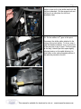
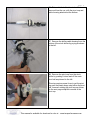
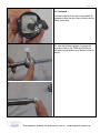
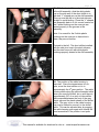
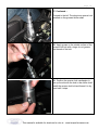
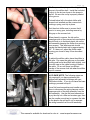
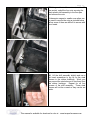
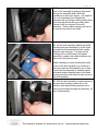
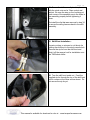
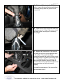
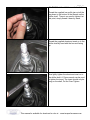
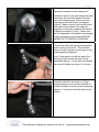
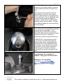
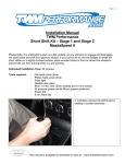
Page 1
Installation Manual
TWM Performance Short Shifter
Cobalt SS Supercharged
Please Note: It is preferable to park on a flat surface, as you will have to engage and disengage
the hand brake and shift from gears to neutral. If you cannot do so and are obliged to install the
short shifter on a slightly inclined surface, place wooden blocks in front and behind the wheels to
prevent the car from moving while you’re working. Please read this manual completely before
beginning to work on your car.
Estimated Installation Time: 60-75 minutes
Tools required:
• Flat head screw drivers (2 of equal size are recommended)
• Metric socket set with a 13mm socket and a ratchet with an extension
• T-20 and T-25 Torx sockets (or T-20 and T-25 screwdrivers)
• 15mm and 9/16” open ended wrenches
• 5/32 Allen key
• Needle nose pliers
• Wire cutters or sharp scissors
• Flash light or shop light
• Shop towels or rags
• All purpose automotive grease (white Lithium based grease is preferred)
• Telescopic magnet (helpful but not required)
This manual is available for download in color at : www.twmperformance.com
Page 2
1. Remove the rear portion of the center
console surrounding the handbrake. Begin by
lifting up on the handbrake to engage it. This
console piece is held from below with clips at
each corner, lift it from the rear until the clips
release, then continue by lifting the front
portion to release the clips as pictured to the
left.
Remove this piece from the car and put in a
safe place for re-installation later.
2. Remove the cup holder located in front of
the shifter by pulling up as pictured. Remove
this piece from the car and put in a safe place
for re-installation later.
This manual is available for download in color at : www.twmperformance.com
Page 3
3. Unclip the shift boot from the console
surrounding the shifter. Pull up on the boot
frame from the front first, it is held from below
with 2 clips. The rear will come free once the
front is unclipped. You can also push up on
the front of the plastic boot frame from below
by sliding your hand in to the opening created
by removing the cup holders and pulling up
from above simultaneously. Leave the shift
boot in place with the bottom disconnected
from the console.
4. Begin removal of the front part of the
console which surrounds the shifter by lifting
the handbrake up. Now lift from the rear as
pictured to the left to release the clips securing
it from below.
With the rear unclipped, lift on the front portion
of the console to release the clips along the
edge as pictured. Do not attempt to remove
this portion of the console yet as there are
connectors to unplug beneath it as described
in the following step.
This manual is available for download in color at : www.twmperformance.com
Page 4
5. Unplug the connector beneath the rear
passenger side corner of the portion of the
console you just unclipped. There is a tab to
depress on the clip and then it can be pulled to
disconnect it from the console.
Now unplug the connector beneath the front
driver’s side corner of the portion of the
console. There is a tab to depress on the clip
and then it can be pulled to disconnect it from
the console.
6. With both connectors free, the front portion
of the console can now be removed from the
car. This is simplified with the handbrake
pulled all the way up. Slide the shift boot and
frame through the hole for the shifter and lift
the console up and out of the car. This may
be simplified by rotating the console as
pictured.
Remove this piece from the car and put in a
safe place for re-installation later.
This manual is available for download in color at : www.twmperformance.com
Page 5
7. Slide the head of a flat head screwdriver
under the shift pattern piece on top of the shift
knob and pry it up and off. In some models
this piece is simply glued on, while others have
2 tabs beneath the shift pattern piece. Lift one
side gently and work your way around the
bottom of the shift pattern to avoid damaging
the tabs beneath it.
8. Remove the shift pattern piece and
determine if your shift knob has a Torx screw
holding the shift knob in place. Early models
tend not to have a Torx screw as pictured
below left, while later models do, as pictured
above left. This Torx screw secures the shift
knob to the shifter shaft so it must be removed.
If your car does not have a Torx screw, skip
the next step and proceed to step 10.
This manual is available for download in color at : www.twmperformance.com
Page 6
9. Use a ratchet and a T-25 Torx bit to
unscrew the Torx bolt on top of the shift knob.
10. USE CAUTION DURING THIS STEP:
To remove the shift knob, insert 2 equal size
flat head screwdrivers between the shift knob
and the top of the reverse lock as shown. The
shift knob must be pried upward to separate it
from the shifter shaft. This step requires some
force, and the help of an assistant is beneficial.
While one person pries upward on the shift
knob, the other can pull upward on the shift
knob to separate it from the shaft. The shift
knob cannot be twisted as the shaft has
splines, however the assistant can pull upward
while attempting to turn the shift knob back
and forth. If your assistant is pulling up on the
shift knob, be careful when it comes free.
11. Remove the shift knob and the reverse
lock spring, as well as the foam piece
surrounding the spring. These pieces will not
be re-installed.
This manual is available for download in color at : www.twmperformance.com
Page 7
12. Pull up on the reverse lock portion of the
shifter to slide it off of the shifter shaft with the
shift boot attached. Put the reverse lock and
shift boot in a safe place for shift boot
installation later.
13. Put the shifter in 4th gear at this point.
Disconnect the shifter cable attached to the
bottom of the stock shifter. To do so, use a
small flat head screwdriver to pry on the front
of the grey cap to pop it open. It will not open
all the way, it should just click open slightly
relieving tension on the cable allowing it to
slide freely on the yellow threaded portion of
the cable as pictured to the left.
This manual is available for download in color at : www.twmperformance.com
Page 8
14. Use a ratchet with an extension and a T20 Torx bit to remove the four (4) Torx screws
at each corner of the top of the shift assembly.
A T-20 Torx screwdriver can also be used as
these screws are not very difficult to remove.
With the screws removed lift the black plastic
cap off the shift assembly and put in a safe
place for re-installation later.
15. Lift the stock shifter out of the shift
assembly with the pivot cup and black plastic
cable housing attached. The shifter may need
to be turned slightly for the cable housing
attached to the bottom to clear the hole in the
shift assembly.
This manual is available for download in color at : www.twmperformance.com
Page 9
16. Pictured to the left is the stock shifter
removed from the car, with the pivot cup and
cable housing attached at the bottom.
17. Remove the shifter cable housing from the
bottom of the stock shifter by prying as shown
to the left.
18. Remove the pivot cup from the stock
shifter by pushing it down and off the main
pivot ball as pictured to the left.
This step requires some force to get the pivot
cup past the plastic bump stop below the pivot
ball, however rotating the pivot cup as shown
on the next page simplifies removal of the
pivot cup.
This manual is available for download in color at : www.twmperformance.com
Page 10
18. Continued…
Pictured to the left is the pivot cup rotated 45
degrees to allow the pivot cup to slide over the
plastic bump stop.
19. Use white lithium grease to grease the
large pivot ball on the TWM short shifter as
well as the small bottom pivot ball as shown to
the left.
This manual is available for download in color at : www.twmperformance.com
Page 11
20. Install the pivot cup on to the TWM short
shifter with the groove on the same side of the
ball as the side arm on the shifter.
21. Pop the shifter cable housing on to the
bottom pivot ball of the TWM short shifter.
This is easily performed by placing the cable
housing on a firm flat surface and pushing the
shifter pivot ball in to it as shown to the left.
22. Install the TWM short shifter with pivot cup
and cable housing attached into the shift
assembly.
Note: It is important to slide the yellow
threaded shifter cable in to the cable housing
on the bottom of the short shifter while placing
the short shifter in to the shift assembly.
Do not close the grey plastic cap on the cable
housing yet, it will need to be adjusted later.
This manual is available for download in color at : www.twmperformance.com
Page 12
23. With the short shifter and pivot cup seated
in the shift assembly, slide the white plastic
cup on the side arm of the short shifter in to
the steel “L” shaped arm on the shift assembly.
This cup must be slid in to the steel side arm
straight to avoid binding. Place the “L” shaped
arm assembly back in to it’s correct location so
the 2 white bushings on the cross pin are
seated properly in the grooves in the
assembly.
Note: It is normal for the 2 white plastic
bushings on the cross pin to have slots in
them, they are not broken.
Pictured to the left: The short shifter installed
with the side pivot cup in the steel side arm,
and the steel cross pin with white plastic
bushings properly seated in the shift assembly.
24. The position of the cable housing is
important. Since the transmission is in 4th
gear, move the short shifter so it is in
approximately the 4th gear position. The cable
housing slides along the yellow threaded cable
when you move the shifter, do so until there is
approximately 3/8” of an inch of silver shifter
cable exposed between the front of the grey
plastic cap and the plastic sheath of the shifter
cable. The grey cover on the cable housing
can now be closed to secure it to the shifter
cable. This can be adjusted later by popping
the cable housing open again with a small flat
head screwdriver if the position is not quite
right.
This manual is available for download in color at : www.twmperformance.com
Page 13
25. Re-install the black plastic cap on top of
the shift assembly, which you removed in step
14. Use a ratchet with an extension and a T20 Torx bit to re-install the four (4) Torx screws
at each corner of the top of the shift assembly.
A T-20 Torx screwdriver can also be used as
these screws do not need to be extremely
tight. Do not over tighten.
26. Apply white lithium based grease to the
smooth part of the shifter shaft as shown to the
left. Avoid getting grease on the shifter
threads at the top of the shaft and in the hole
on the side of the shaft, only apply grease to
the smooth part of the shifter shaft.
27. Install the aluminum reverse lock on to the
shifter shaft with the slot facing the passenger
side and slide it down the shifter shaft.
This manual is available for download in color at : www.twmperformance.com
Page 14
27. Continued…
Pictured to the left: The aluminum reverse lock
installed on the greased shifter shaft.
28. Apply grease to the outside surface of the
reverse lock bolt with o-rings, do not grease
the threads of the bolt.
29. Position the reverse lock mechanism to
line up the slot with the hole in the shifter shaft.
Install the reverse lock bolt and thread it in by
hand until it stops.
This manual is available for download in color at : www.twmperformance.com
Page 15
30. Use a 5/32 allen key to tighten the reverse
lock bolt.
31. Slide the included plastic bushing with the
smaller diameter facing down over the
threaded part of the shifter shaft. Drop the
bushing down into the reverse lock mechanism
as far as it will freely slide in.
32. Slide the reverse lock spring with the
white delrin bushing (included with the short
shifter) down in to the reverse lock as shown.
The bottom of the spring will contact the
bushing you slid in to the reverse lock in the
previous step. If you look down in to the
reverse lock you should see the bottom
bushing installed in the previous step sitting
flush at the bottom of the opening in the
reverse lock.
This manual is available for download in color at : www.twmperformance.com
Page 16
33. Compress the spring and bushing past the
groove in the shifter shaft. Install the included
e-clip in to the slot as shown in the image to
the left. Be sure the e-clip is properly seated
in the groove.
Pictured below left is the short shifter with
reverse lock installed and the reverse lock
bushings, spring, and clip in place.
Test the short shifter now to ensure that it
goes in to every gear, including reverse by
lifting up on the reverse lock.
When placed in reverse, the tab on the
passenger side of the reverse lock mechanism
should hook on to the black plastic tab on the
shift assembly keeping the shifter from moving
from reverse. This aluminum tab should
overlap the black plastic tab by approximately
1/2". If it does not, adjust the shifter cable
housing you closed in step 24 as described
below.
To adjust the shifter cable, place the shifter in
4th gear. Pop open the grey cap on the cable
housing and move the shifter back slightly, and
close the cap on the cable housing to secure
the cable. Do so until there is sufficient
overlap of the reverse lock tab when the shifter
is put in reverse.
34. PLEASE NOTE: The following steps are
only required if you have purchased the
optional shift assembly bushings with your
TWM short shifter. If you do not have the base
bushings, proceed to step 41.
Use a flat head screwdriver and needle nose
pliers to disconnect the wiring harness on the
passenger side of the shift assembly from the
shift assembly. Use the flat head screwdriver
to pry the clip out a little and create a gap, then
use the needle nose pliers to squeeze the tabs
on the plastic clip and pull it out to separate
the wiring harness from the shift assembly.
This manual is available for download in color at : www.twmperformance.com
Page 17
35. Using a ratchet with an extension and a 13
mm socket, unbolt the four nuts securing the
black plastic shift assembly to the floor pan
and remove the nuts.
A telescopic magnet or needle nose pliers can
be used to remove the nuts as pictured below
left as some of them are difficult to access with
your hands.
36. Lift the shift assembly slightly and use a
flat head screwdriver to pry up on the steel
sleeves in the rubber bushings. Work your
way around the steel sleeves to free them from
the rubber bushings. Repeat for all four
corners of the shift assembly. These steel
sleeves will not be re-used so they can be set
aside.
This manual is available for download in color at : www.twmperformance.com
Page 18
37. Remove the rubber bushings from the
base of the assembly by pushing them down
through the assembly with a flat head
screwdriver or with your fingers. It is helpful to
pull on the bushings from beneath the
assembly with your fingers while pushing them
down through the top with your other hand.
Repeat for all four corners of the shift
assembly. These rubber bushings will not be
re-used so they can be set aside.
38. Lift the shift assembly slightly and install
the aluminum base bushings on to the studs
beneath the shift assembly with the smaller
diameter step facing up. This step on the
bushings fits in to the holes in the plastic
assembly to replace the rubber bushings you
removed in the previous step.
Install a bushing on each stud beneath each
corner of the shift assembly one corner at a
time and lower the shift assembly on to them.
Ensure that the assembly is seated properly
with each smaller diameter step on the base
bushing inserted in the holes at each corner of
the shift assembly.
39. With the shift assembly properly seated on
the aluminum bushings, place one of the
stainless steel base bushing washers on to
each stud protruding through the assembly, on
top of the assembly.
This manual is available for download in color at : www.twmperformance.com
Page 19
40. Secure the shift assembly back in place
with the stock nuts and a 13mm socket and
ratchet. Be sure the step on the bushings at
each corner of the assembly are in the holes in
the assembly properly before tightening it
down.
Re-install the clip that was removed in step 34
to secure the wiring harness back to the shift
assembly.
41. Shift Boot Installation :
Use wire cutters or scissors to cut the zip tie
holding the shift boot to the stock reverse lock.
Remove the zip tie from the shift boot and
slide it off the reverse lock for installation onto
the TWM short shifter.
42. Turn the shift boot inside out. Feed the
supplied zip tie through the top of the shift boot
until it comes out the other end as shown. Do
not secure the zip tie yet.
This manual is available for download in color at : www.twmperformance.com
Page 20
43. Slide the shift boot on to the TWM short
shifter. Line up the top of the boot with the zip
tie passing through with the groove on the
reverse lock.
44. Tighten the zip tie to secure the shift boot
to the reverse lock. Snip off the excess zip tie
with wire cutters ensuring not to leave any
sharp edges.
45. Replace the front portion of the console
and slide the shift boot up through the cutout
for the shifter. Re-connect the plastic
connectors beneath this portion of the console
and snap it back in to place by reversing steps
1 to 6. Rotate the shift boot to ensure it is
facing the right direction and clip it back in
place on the console, slide the rear tabs in first
then press down on the front to seat it
properly.
Re-install the rear portion of the console that
was removed in step 1.
This manual is available for download in color at : www.twmperformance.com
Page 21
46. Shift Knob Installation and orientation:
Thread the supplied low profile jam nut all the
way down to the bottom of the threads on the
shifter shaft. There is no need to tighten it at
this point, simply thread it down by hand.
Thread the supplied aluminum insert on to the
shifter shaft by hand with the hex end facing
up.
Now lightly tighten the aluminum insert on to
the shifter shaft. A 15mm wrench can be used
to tighten the insert. The insert should only be
snug on the shaft, Do Not Over Tighten.
This manual is available for download in color at : www.twmperformance.com
Page 22
Thread the shift knob on to the insert until you
experience resistance at its lowest point.
Pictured to the left is the point where the insert
encounters the top of the inside of the shift
knob and it stops turning. Notice how the
engraving on the shift knob is not aligned
correctly. Make a note of how much the shift
knob needs to be backed off to align the
engraving, in this case it needs to be backed
off slightly more than 1/4 turn. Please note
that it is impossible to thread the insert deeper
to align the engraving, the insert MUST BE
BACKED OFF COUNTER CLOCKWISE.
Unscrew the shift knob leaving the aluminum
insert in place on the shaft. This will allow
access to adjust the jam nut and insert to set
proper engraving alignment.
Use a 15mm wrench on the hex end of the
aluminum insert to back the insert off the
appropriate amount. In this case we will back
the insert off slightly more than 1/4 of a turn.
Pictured to the left is the insert in it’s final
resting position once it has been backed off
counter clockwise to ensure proper engraving
alignment. Continue to hold the insert in this
position.
This manual is available for download in color at : www.twmperformance.com
Page 23
While still holding the insert in place, thread
the jam nut up the shaft (counter clockwise)
until it touches the bottom of the aluminum
insert.
Still holding the insert in position with the
15mm wrench, use a 9/16” open ended
wrench to tighten the jam nut up against the
bottom of the insert. Do not tighten the insert
down as this will change the engraving
orientation. Simply hold it in position while
tightening the jam nut from below. The jam
nut is tightened against the insert by rotating
counter clockwise.
Re-install the shift knob and tighten down by
hand. If the insert was adjusted correctly the
engraving will line up properly. If the
engraving does not quite line up properly,
remove the shift knob and re-adjust the insert
and jam nut to line it up. Only minor
adjustments should be required at this point.
PLEASE NOTE: if you re-adjust the knob,
loosen the jam nut FIRST by holding the
aluminum insert with a 15mm wrench and
rotating the jam nut CLOCKWISE with the
9/16” wrench. Do not loosen the insert first,
simply hold it with the 15mm wrench and
loosen the jam nut beneath to maintain
approximately the correct orientation of the
insert.
Congratulations, the installation is
complete. Enjoy your new Short shifter.
Thank you, for choosing
This manual is available for download in color at : www.twmperformance.com
Page 24
Legal Disclaimer
TWM Performance is not responsible for the misuse, incorrect installation, or failure of any product we sell.
Under no circumstances, including but not limited to negligence, will TWM Performance be liable for special or consequential damages that result
from the use or inability to use our products. TWM Performance does not assume responsibility for any damage to the user, passenger or vehicle
resulting from the operation of a TWM Performance product.
TO PROTECT USERS FROM INJURY OR DEATH. THE USER ASSUMES ALL RISKS. Autocrossing, track events, and high speed driving are all
dangerous activities - always drive responsibly and safely.
Warranty
Installation of some TWM Performance products may or may not void factory warranties. Always keep OEM equipment that has been replaced in
case work is required at the dealer or the vehicle is sold.
This warranty covers the original purchasing consumer. This warranty is limited to repair or replacement by TWM Performance of any TWM
Performance product that fails because of a defect in materials or workmanship.
Warranty does not cover the following:
-Damage incurred to related vehicle components
-Regular day to day wear on vehicle
-Shipping costs for replacements
-Installation costs and vehicle down time
-Products that have been modified, incorrectly installed or misused.
-Mounting hardware and bearings
This manual is available for download in color at : www.twmperformance.com