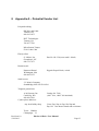
1
Harlan 12 Drive User Manual Microdrive used for manually driving tetrodes for electrophysiology recordings Neuralynx, Inc. 105 Commercial Drive, Bozeman, MT 59715 Phone 406.585.4542 • Fax 866.585.1743 www.Neuralynx.com Revision 1.0 5/30/2013 [email protected] Table of Contents 1 2 3 4 5 6 7 8 9 10 Document Overview ............................................................................................................... 3 Harlan 12 Drive Overview ...................................................................................................... 3 Glossary .................................................................................................................................. 4 Drive Specifications ................................................................................................................ 5 Drive Preparation .................................................................................................................... 6 Microdrive Implantation ....................................................................................................... 11 Recycling the Microdrive ..................................................................................................... 13 Appendix A – Potential Vendor List .................................................................................... 15 Appendix B – Replaceable Tip Hole Patterns ...................................................................... 17 Appendix C – Microdrive Parts Identifier ............................................................................ 20 List of Figures and Tables Figure 5.1 Initial Telescoping Tube Assembly ............................................................................... 7 Figure 5.2 Final Telescoping Tube Assembly ................................................................................ 8 Figure 5.3 Drive Assembly ............................................................................................................. 8 Figure 5.4 Assembly Fixture........................................................................................................... 9 Figure 10.1 Custom Exit Hole Template ...................................................................................... 18 Figure 10.2 Custom Exit Hole Graph Paper ................................................................................. 19 Figure 11.1 Microdrive Parts Identifier ........................................................................................ 20 Figure 11.2 Neuralynx's EIB-36-12TT and EIB-27-12TT ........................................................... 20 Revision 1.0 5/30/2013 Harlan 12 Drive User Manual Page 2 1 Document Overview The purpose of this manual is to outline assembly, loading, and general implantation of the Harlan 12 microdrive. It also describes the appropriate preparation and recycling procedures surrounding the experiment. Step-by-step instructions are outlined and additional products like the Drive Assembly Fixture are recommended to further facilitate this process. 2 Harlan 12 Drive Overview The Harlan 12 Drive is a 12-tetrode microdrive that allows for recordings from a single brain structure or from two or more structures that fall on one line that extends from the skull surface into the depths of the brain. The exit tip of this drive is solid and can be drilled by the researcher into their desired exit pattern, or can be custom drilled for a small fee. For initial drive preparation, assemblies of telescoping polyamide tubes must be built and attached to the microdrive. The Drive Assembly Fixture aids with loading and the tube assemblies are inserted into the drive plate and bonded with an adhesive. The tetrodes are fed through the guide tubes and the assembly is inserted with drive screws into the cone. The tetrodes are gold-plated, the cone components are assembled, and the drive is ready for experimentation. A general implantation outline is provided, but there will be variations according to particular animals and objectives of the research to be accomplished. After experimentation, recycling guidelines describe how the drive can be reused on other animals with a new replaceable tip and new polyamide tube assemblies. Ray Harlan is the maker of this drive and can be contacted at: Specialty Machining 15 Happy Hollow Road Wayland, MA 01778 Phone and FAX (508) 358-4013 [email protected] Revision 1.0 5/30/2013 Harlan 12 Drive User Manual Page 3 3 Glossary Inner Diameter (ID) – the inner diameter of the polyamide tubing Outer Diameter (OD) – the outer diameter of the polyamide tubing EIB – Electrode Interface Board Revision 1.0 5/30/2013 Harlan 12 Drive User Manual Page 4 4 Drive Specifications Travel for each drive 10.5 mm Travel for each revolution of the drive screw 160 micrometers Tip area available for electrodes 3.9 x 5.9 mm Height of microdrive 53.5 mm Diameter of microdrive 34.1 mm Weight Without Cover With Cover 8.3 grams 9.3 grams Revision 1.0 5/30/2013 Harlan 12 Drive User Manual Page 5 5 Drive Preparation Before the microdrive can be used, the replaceable tip must be drilled and assemblies of telescoping polyamide tubes must be built and attached to the microdrive. These tubes provide the rigidity needed to precisely deliver the tetrode tips to the intended locations. For each drive, one tube is attached to a guide tube in the replaceable tip. Three other tubes are telescoped together and attached to the drive plate. After the drive is installed in the microdrive, the tetrode is inserted in the innermost tube and bonded to it. Four or more sizes of polyamide tubing are used in the microdrive. The exact sizes and wall thickness may not always be available from tubing vendors. There is some flexibility in choosing sizes; it is best to try to get wall thickness specified here and adjust diameters as needed. Try to provide .001-.003 in. diametral clearance between telescoping pairs of tubes. The recommended sizes, from smallest to largest, are: .0056” OD, .0035”ID, .001” wall .010” OD, .008” ID, .001” wall .012” OD, .0065” ID, .0028” wall .0196” OD, .0135” ID, .0030” wall Guide tubes in the replaceable tip may vary from .022” to .051” ID. The following steps will ensure properly working drives. Careful attention paid to tube lengths and assembly geometry will make the job of installing the drives easier. 1. Remove the cover of the microdrive and the replaceable tip. Remove the upper cone. Store the small screws in a secure place. Remove all of the drives. Cut a piece of insulated tungsten ground wire for the ground approximately 150 mm long. Strip the insulation off both ends. From the bottom of the lower cone, feed the wire into the ground-wire hole in the body. This hole will be located between two drives near the outer periphery of the body and near the rear of the drive. Slide the wire through until the end can be inserted into the ground hole on the connector board. Secure it with a cactus needle and break off excess needle. Insert the other end through the exit hole in the lower cone, using forceps. Pull the wire through, leaving sufficient slack so that the wire won’t snag on a drive. Solder a lug, fashioned from copper-tin foil to make good contact with the ground screw. The excess wire can be wrapped around the lower cone and taped in place temporarily with small bits of Scotch tape. 2. Choose tip guide tube sizes and locations, following instructions provided in Appendix B, Replaceable Tip Hole Patterns. The following list gives the tube inside diameters for a range of numbers of tetrodes going through one guide tube. Revision 1.0 5/30/2013 Harlan 12 Drive User Manual Page 6 It is assumed that the lower telescoping tube is .010” OD. Wall thicknesses are suggested to be .002” - .003”. No. of tetrodes ID 1-3 4-7 8-12 Guide tube .022” .031” .045” 3. Cut one piece of each size of tubing for each drive to be assembled. Use a new single or double-edged razor blade to avoid crushing the tubing. Cut the following lengths: a. b. c. d. 15 mm of .0056” OD 43 mm of .010” OD 2 mm of .012” OD 13 mm of .0196” OD The .012” tube is used as a spacer between the .0056” and .0196” tubes. The thicker wall helps center the small tube. The .010” tubing can be used instead, if a small quantity of the .012” tubing cannot be obtained (ask for a sample one- foot piece, which will make 150 assemblies). 4. Slide the 2- mm length .012” tube over the .0056” tube so that ½ mm of the small tube extends past the end of the .012” tube. Bond these together with a thin or gapfilling Cyanocrylate adhesive, such as Zap or Zap-A-Gap. Use the point of a straight pin, needle or a flat-tip oiler (black) to apply the tiniest drop of adhesive and then use some accelerator if the bond does not set quickly. Be very careful not to get any adhesive inside the smaller tube. The thinner adhesive seems to do a cleaner job. Cut cured adhesive off the applicator frequently. Figure 5.1 Initial Telescoping Tube Assembly 5. Insert this assembly, .0056” tube first, into the .0196” tube until ½ mm of the .012” tube extends past the end of the large tube. Bond this assembly together as in Step 4, again being careful not to get adhesive in the small tube. Note that the .0056” tube extends about 1 mm past the bottom end of the .0196” tube. This helps when inserting it into the .010” tube in the drive. The top of the assembly should look like a stepped cone, with both .012” and .0056” tubes extending equal amounts from their next larger tubes. Revision 1.0 5/30/2013 Harlan 12 Drive User Manual Page 7 Figure 5.2 Final Telescoping Tube Assembly 6. Insert the drive screw into the Drive Assembly Fixture hole furthest from the top end of the fixture. Push it in until the retaining nut seats against the fixture. Insert the tube assembly into a drive plate and assembly fixture until the .0056” tube at the bonded-end extends 2mm past the top surface of the plate. Bond the assembly to the plate with Cyanocrylate adhesive. If a gel-type adhesive is used, it is possible to just put a tiny fillet between the tube and drive plate and not have it wick down the hole. This will facilitate removing the tube to recycle the microdrive. Accelerator must be applied to achieve curing. A small bottle that has a Luer top that can take a hypodermic needle is ideal for putting just a tiny drop on the glue. Try not to touch the needle to the glue; it can get clogged. Use a 26-gauge or finer needle, hold the bottle inverted and just let gravity form a drop on the tip of the needle. Figure 5.3 Drive Assembly 7. Cut the tip guide tubes to 5 mm long. Insert them into the holes drilled in the replaceable tip. They should extend exactly 2 mm beyond the end of the tip. Bond them in place with Cyanocrylate adhesive. Revision 1.0 5/30/2013 Harlan 12 Drive User Manual Page 8 Figure 5.4 Assembly Fixture 8. Disassemble the microdrive by removing the upper cone. Leave the lower cone attached to the body of the microdrive. Secure the replaceable tip in the smaller Assembly Fixture clamp, with the guide tubes facing to the left. Place the body in the larger clamp, with the connector board to the right. Orient each so that drive number 1 and the tip hole to be used for its tetrode are closest to you. 9. Insert the first intermediate tube (.010” OD) into the appropriate tip guide tube and thread it into the body hole for the first drive. Push it through until it exits the body hole. Continue inserting intermediate tubes for the other drives, rotating the tip and body to facilitate handling the tubes. 10. When all tubes are in place, loosen the tip clamp and push the tip onto the body. Fasten it with the 00-90 hex- head screws supplied. 11. Slide the intermediate tubes out of the tip guide tubes until ½ mm remains above the upper body surface. Be especially careful when moving tubes that have neighbors in the same guide tube. Friction could cause more than one tube to move, disturbing the location of previously set tubes. These may have to be held in place with fingers or some other clamping arrangement. When all tubes are located in the body correctly, bond them to the tip guide tubes with Cyanocrylate adhesive. Be sure to fill all voids between tubes with adhesive. Then cut the tubes off flush with guide tubes (2 mm from the end of the tip). 12. Place a drive over the guide pins of the first drive so the pins enter the holes in the drive plate. Slide the drive down until the smallest tube almost touches the intermediate .010” tube. Guide the small tube into the .010” tube as the drive is moved further downward. The drive screw now can be engaged in the body threads to move the drive. Guide the outer tube over the .010” tube as the drive is advanced. 13. When all the tubes are telescoped, test the freedom of the assembly by advancing the drive over the full travel range (10.5 mm). Add the other drives and test their Revision 1.0 5/30/2013 Harlan 12 Drive User Manual Page 9 travel. If there is any binding, inspect the intermediate tubes near the bottom of the body to be sure there is no kinking. Remove the drive and check that a separate piece of .010” tubing can be slid into the drive tube assembly up to the drive plate. If excess Cyanocrylate has been used, it may have wicked between the tubes and bonded them together. If so, replace the tube assembly with another. If the outer tube does not pull out of the drive plate fairly easily, soaking the tip of the drive plate in water for a few hours should soften the Cyanocrylate. Try to keep the screw out of water. 14. Make up the tetrodes according to your standard procedure. Back off the drives until the heads of the drive screws are just below the ends of the guide pins. This should keep the outer tubes in the body holes. Insert the tetrodes in the inner tubes and slide them through until they are just flush with the tip guide tubes. Bond them with Cyanocrylate adhesive to the tops of the inner tubes. 15. Cut the tetrodes at 29 mm above the ends of the inner tubes. Separate about 6 mm of the wires and feed them into their respective recording channel holes on the connector board. The end of each wire should extend about 2 mm above the top of the board. Insert a cactus needle into each hole from the top of the board and push firmly to ensure contact of the wire with the circuit trace. Break off the excess cactus needle. Break off excess tetrode wire with forceps. 16. After all the wires have been connected, dress them away from the guide pins so there is no chance of binding or snagging as the drives are advanced. 17. Gold plate the tetrodes using your standard protocol. 18. Retract the tetrodes by backing out the drive screws until they are just free of the body. Seal the intermediate tubes by touching the end of the guide tubes to a light mineral oil. Blot off excess oil with an absorbent wiper. The microdrive now is ready for implantation. Revision 1.0 5/30/2013 Harlan 12 Drive User Manual Page 10 6 Microdrive Implantation The following outline is meant to be a general guide to implanting the microdrive. There will be variations according to particular animals and objectives of the research to be accomplished. 1. Shave head area around location of incision. 2. Secure anaesthetized animal in stereotactic fixture. 3. Make incision and hold skin apart with appropriate clamps. 4. Scrape away tissue over the skull. 5. Attenuate any bleeding. 6. Mark the stereotactic reference point on the skull (e.g. Bregma) with finepoint permanent marker. 7. Insert pointer in stereotactic holder and move over reference point. Record axes coordinates. 8. Calculate burr hole coordinates. Move stereotactic holder to first hole and mark location with permanent marker. Repeat for other holes. Remove pointer. 9. Mark locations for anchor-screw holes and ground hole. 10. Drill screw holes with small dental burr, being very careful not to penetrate the dura. For the ground hole, the dura is pierced. 11. Insert anchor screws (suggested screws: 3/32” 00-90 or 0-80 hex-head screws). The bottoms of the heads should clear the skull by .5 to 1.5 mm. 12. Drill the burr holes with a core drill (approx 1.3 mm dia). Do not penetrate the dura. 13. Carefully scrape away the dura in the burr holes. 14. Attach the microdrive holder to the Stereotactic Adapter. Attach the microdrive to the holder. 15. Move the first guide tube over the stereotactic reference point and lower the microdrive until the guide tube clears the skull by less than 1 mm. Adjust the A-P and Lateral coordinates until the guide tube is well centered over the Revision 1.0 5/30/2013 Harlan 12 Drive User Manual Page 11 reference mark. Record the coordinates. 16. Calculate the new coordinates for the first guide tube and move the stereotactic fixture to them. All of the guide tubes should be near the centers of their burr holes. 17. Unwrap the ground wire from the lower cone and attach it to the proper screw. Take up excess slack in the wire by wrapping it back and forth around a pair of adjacent screws. 18. Lower the microdrive until the guide tubes touch the brain surface. 19. Fill around the bottom of the replaceable tip with Vaseline to seal the tip. 20. Mix small batches of dental acrylic and fill around screws and the replaceable tip, slowly building up the mass with sequential batches. Cover the screws, ground wire and build up around the larger diameter of the replaceable tip. Avoid getting cement on the lower cone, except to secure the ground wire. Also, if cement is kept away from the replaceable tip attachment screws, recycling the microdrive will be considerably easier. The final shape of the cement mass should be smoothly formed around the tip and feathered out onto the skull to facilitate comfort for the animal. 21. Suture the incision, bringing the skin over some of the dental acrylic. Do not pull too tight. 22. Release the microdrive and remove the holder. Remove the animal from the stereotactic fixture. Revision 1.0 5/30/2013 Harlan 12 Drive User Manual Page 12 7 Recycling the Microdrive After the microdrive has been removed from the animal, it can be recycled for further use on other animals. Because of the nature of various bonding techniques, some parts must be discarded. These include the replaceable tip and all of the polyamide tubes. If care is taken when removing the tube assemblies from the drive plates, the drives will be fully reusable. The outline below suggests a sequence to be followed. 1. Remove the replaceable tip. If dental acrylic has been kept away from the attachment screws and most of the cone, then only chipping it away from around the ground wire will be required. Carefully work the adhesive off with a sharp knife until the tip can be removed. Avoid cutting into any part of the lower cone. When the tip is pulled away, all of the intermediate tubes will go with it. If there is any cement on the cone that isn’t easily scrapped away, it can be softened by soaking the cone (still attached to the body, but with drives removed) in a shallow dish of acetone for an hour. This makes the cement somewhat rubbery. 2. Remove the drives. Cut the tetrode wires with scissors and the drives should be readily removable. 3. Remove the tube assemblies from the drive plates. Cut the top of the tubes and any glue fillet off flush with the top of the drive plate with a sharp razor blade. If care was taken to minimize the amount of Cyanocrylate used to attach the assembly to the plate, the tube should pull out fairly easily. If it resists use a .022” dia drill in a pin vise to clean out the tube remaining in the hole. Be very careful not to twist the drill sideways in the hole and put excessive strain on the drive plate. Do not apply any pressure to the drive screw or it may bend. Do not attempt to use any debonder or othe r solvent to soften the adhesive; they may produce stress cracks in the plastic drive plate. 4. Remove tetrode wires from the connector board. It may be helpful to remove the board from the microdrive (make note of the orientation of the board on the microdrive.) Some cactus needles will protrude through the board by 3 or more millimeters. It may be best to cut all of the needles off with diagonal pliers so that about 1 mm protrudes. Use a flat-bladed screwdriver to pop the cactus needles back up through the plate. Try to push on them straight along their axes to avoid bending and breaking. If some do break, use a flat-ended piece of .015” music wire (available at hobby shops), held in a pin vise, to push on the cactus needle. The wire should extend only about ½ mm from the pin vise for the first push. It may have to be extended more to push the loosened cactus needle out of the board. After all of the needles and bits of tetrode wire have been removed from the board, replace it on the microdrive. At this point, the microdrive should be ready to be reassembled with new polyamide Revision 1.0 5/30/2013 Harlan 12 Drive User Manual Page 13 tube assemblies and a new replaceable tip. Revision 1.0 5/30/2013 Harlan 12 Drive User Manual Page 14 8 Appendix A – Potential Vendor List Polyimide tubing PD Wire and Cable Trenton, GA 800.241.1075 HVT Technologies Trenton, GA 706.657.7700 MicroLumen Tampa, FL 813.886.1200 Flat-tip oilers S. LaRose, Inc. Greensboro, NC 888.752.7673 Part No. OL-350 (extra small - black) Dental acrylic Patterson Dental Wilmington, MA 800.842.5355 Hygenic Repair Resin, veined Small screws J. I. Morris Company Southbridge, MA 508.764.4394 Tungsten ground wire A-M Systems, Inc. Carlsborg, WA 800.426.1306 Cyanocrylate adhesives Any local hobby shop Catalog No. 7960 (.003” wire, .0045” dia insulated) Pacer Zap, Zap-A-Gap, Slo-Zap and Zap Gel. Also house brands and accelerator. Tower Hobbies Champaign, Il. Revision 1.0 5/30/2013 Harlan 12 Drive User Manual Page 15 800.637.4989 Home Depot Super Glue Gel and Future Glue Gel Dispensing bottle for accelerator Revision 1.0 5/30/2013 Contact East 800.225.5370 Precision Dispenser, Part No. 121-723, Needles, Part No. 121-755 (.009 ID) Small Parts 800.220.4242 Squeeze Bottles, Part No. U-SQB-02, Needles, U-NE-301PL or U-NE-271PL Harlan 12 Drive User Manual Page 16 9 Appendix B – Replaceable Tip Hole Patterns The following instructions are to be used to establish the hole locations and sizes for the Tetrode Microdrive replaceable tips. This will ensure that the tip can accommodate the patterns that you want to use. If your pattern is too large, this procedure will reveal the problem. 1. Draw the proposed pattern on the centimeter graph paper at a scale of 10:1 (millimeters become centimeters). At each hole location mark a dot. 2. Place the graph paper over the template and hold them together against a light table or window so that both sheets can be seen. Select a hole size from the patterns shown. The hole should be slightly larger than the tubing that is to go through it. Slide the graph paper so that the hole outline is centered on the dot (the small circle is an aid to centering). Trace over the hole outline. Repeat this procedure for the remaining proposed holes. Note: holes need not be all one size. 3. Move the graph paper until the hole pattern fits within the oval outline, keeping the flat sides of the oval parallel to the coordinate frame on the graph paper. If this cannot be done, the hole spacing must be reduced or some holes must be eliminated. 4. If the hole pattern does fit within the oval, trace the outline of the oval on the graph paper, record the coordinates of the holes and their sizes and forward the graph paper, coordinates, hole sizes and the replaceable tip to Specialty Machining (15 Happy Hollow Road, Wayland, MA 01778). The pattern will be centered in the oval; therefore it may be slightly displaced from your tracing. If you have questions, call 508.358.4013 or e- mail to [email protected]. Revision 1.0 5/30/2013 Harlan 12 Drive User Manual Page 17 Figure 9.1 Custom Exit Hole Template Revision 1.0 5/30/2013 Harlan 12 Drive User Manual Page 18 Figure 10.2 Custom Exit Hole Graph Paper Revision 1.0 5/30/2013 Harlan 12 Drive User Manual Page 19 10 Appendix C – Microdrive Parts Identifier Figure 10.1 Microdrive Parts Identifier The Harlan 12 Drive is compatible with Neuralynx’s EIB-36-12TT (on left) or modified with EIB-27-12TT (on right). Figure 10.2 Neuralynx's EIB-36-12TT and EIB-27-12TT Revision 1.0 5/30/2013 Harlan 12 Drive User Manual Page 20