1
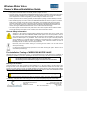
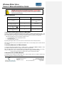
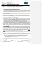
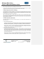
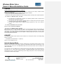
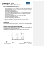
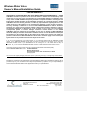
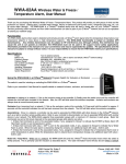
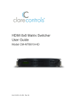
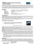
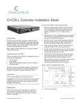
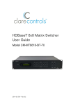
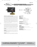
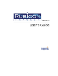
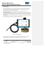
Wireless Water Valve Owner’s Manual/Installation Guide Introduction WIRELESS WATER VALVE is a patented, wireless, water detection and automatic water shut-off system that works as an automatic valve for a home’s main water supply line. It can be easily installed by a certified professional plumber and then configured to work properly. WIRELESS WATER VALVE is a new professional grade, electrically operated water shut-off valve introduced by Clare Controls. Every year nearly 1 million families have their homes ruined and their lives overturned by water damage and the subsequent repairs. The WIRELESS WATER VALVE used in a Z-Wave home automation network along with ZWave water alarm sensors (CH-WWA-02-W), helps to reduce or eliminate water damage caused by leaky pipes or faulty appliances. WIRELESS WATER VALVE can also work as a Water Level / Irrigation device. It can be set up to be on a ‘timed’ schedule using a Smart Controller inside a Z-Wave home automation network. Figure 1.1 – Wireless Water Valve WIRELESS WATER VALVE operates in a Z-Wave enabled home network which uses the latest and most successful wireless home automation technology to provide protection 24/7, 365 days a year. 7519 Pennsylvania Avenue Suite 104 Sarasota, FL 34243 Phone: (941) 404-1072 http://support.clarecontrols.com Made in USA Doc. ID 2013-03-265-1 pg. 1 of 16 Wireless Water Valve Owner’s Manual/Installation Guide System Components The Emergency Water Shut-off Valve System has two basic components: 1. A motorized ball valve and housing containing a wireless Z-Wave radio transceiver which automatically turns off your water supply when any wireless water alarm sensor detects water or low, potentially freezing temperature. 2. One or more wireless water alarm sensors (CH-WWA-02-W), which detect water from a leak or overflow, or detect potentially freezing temperatures, and cause a wireless Z-Wave signal to be sent to the WIRELESS WATER VALVE to turn off the water supply. Package Contents Check the contents of the package with the products listed below, it should contain the following: 1 ea. WIRELESS WATER VALVE 1 ea. Local monitoring probe 1 ea. DC power adapter 1 ea. Owner’s Manual/Installation Guide NOTE: The package may contain CH-WWA-02-W sensors or other Z-Wave devices if purchased as part of a kit. Additional and Optional Components Available: • CH-WWA-02-W water leak detection sensors • Optional Car Battery, 12VDC for power outage backup Product Specifications • WIRELESS WATER VALVE uses a motorized ball valve, (available in multiple sizes, 1/2", 3/4", 1" and 1 1/4"), used to automatically turn off the main water supply when unwanted water is detected due to a leak or overflow. • Many WIRELESS WATER VALVEs can be used and/or programmed into a Z-Wave Home Automation System. • Brass valve with commercial grade seats and seals: Brass valve: full port brass forged body, lead free Seats: RTFE Seals: Viton • General Usage Specifications: Max. Working Pressure…….125 PSIG Ambient Temperature………35° to 105° F For Cold Water Applications • Sizes / Flow (GPM @ 1 PSI pressure drop) ½” 19 1” 52 ¾” 34 1-1/4” 77 • Enclosure: Polycarbonate, NEMA 4x (weather resistant). • Voltage: 110 VAC converted to 12V DC (Class 2 Power converter with 20’ cord), 1.3A full load. Option to install an additional 12V DC battery (car or riding mower) as a power back-up. • Meets the approvals of state and municipal authorities. • Three indicator lights: If the red light is on, it means the valve is closed. The green light means that the valve is open, allowing water to flow freely through the plumbing system. If the yellow light is on or flashing, it means an error or the valve is not programmed into a Z-Wave network. 7519 Pennsylvania Avenue Suite 104 Sarasota, FL 34243 Phone: (941) 404-1072 http://support.clarecontrols.com Made in USA Doc. ID 2013-03-265-1 pg. 2 of 16 Wireless Water Valve Owner’s Manual/Installation Guide • Three panel-mount tactile switches to manually activate / program the valve. • A Z-Wave system, which includes the WIRELESS WATER VALVE in combination with sensors and Z-Wave Gateway Controller (available in kits or separately), can automatically send you an email, text message or phone call (based on controller configuration) if a water leakage or overflow event occurs. • Z-Wave system that can be remotely operated (via internet/phone ) through a Z-Wave Gateway Controller. • When installed properly in a Z-Wave network, the WIRELESS WATER VALVE and its system of CH-WWA02-W sensors constantly monitor the home for water leakage. The CH-WWA-02-W sensors are battery operated, wireless water / moisture / temperature sensors which are strategically placed throughout the home. If one of these sensors trip, a wireless Z-Wave radio signal is relayed through the Z-Wave home network causing the WIRELESS WATER VALVE to turn off the household water supply. • The Z-Wave system can also include many other devices from other companies that are Z-Wave certified such as light switches, thermostats, scene controllers, and other useful Z-Wave devices. General Safety Information Adherence to all local and municipal building, plumbing and electrical codes as they pertain to the installation of the water valve WIRELESS WATER VALVE System is of utmost importance. Codes in some areas may require that a licensed plumber be employed to do the installation, or that the proper permits be obtained prior to any installation. Even if local codes do not require a licensed plumber to do the installation, it is necessary that the installer has a professional level of competence in both plumbing and electrical skills to perform the installation. These instructions assume this level of knowledge and skill. If in doubt, use a licensed professional. Disconnect power source before working on or servicing the unit. Failure to do so could result in serious personal injury. It is strongly recommended that eye protection be worn while servicing the system. Failure to do so could result in personal injury. Pre-installation Testing of WIRELESS WATER VALVE Although each unit is pre-tested at the factory, it is recommended that the unit be tested prior to installation to ensure proper operation in your home. Operating the valve before connecting to the water line will not damage it. Use caution! The valve closes with enough force to cut off a finger. Be extremely careful to ALWAYS keep fingers and other items out of the valve. Manually Test the Valve Check the position of the valve by looking in either threaded end. In the open position, you will be able to see through the valve; in the closed position only the shiny surface of the ball will be visible. Place the base of the housing on a sturdy surface, as close as feasibly possible to the location where it will be permanently installed. With your fingers and other people and items away from the valve, plug the Water Valve WIRELESS WATER VALVE power adapter cord into a nearby 110V AC outlet. Use Caution! The valve may open or close automatically as soon as it is plugged in! The open or closed indicators should show the status, as appropriate. Within 10 seconds, status indicator light will start blinking. Grasp both sides of the housing (not the valve) with valve pointing away from you for safety. 7519 Pennsylvania Avenue Suite 104 Sarasota, FL 34243 Phone: (941) 404-1072 http://support.clarecontrols.com Made in USA Doc. ID 2013-03-265-1 pg. 3 of 16 Wireless Water Valve Owner’s Manual/Installation Guide Being very careful not to have your fingers or other objects near the valve openings, press the colored circle just below the unlit indicator light of the opposite valve position. You will hear the motor change the valve position. Again, look into the threaded end of the valve to verify that the valve has changed position. If it appears that the valve has not turned from one position to the other, DO NOT try to reposition the valve yourself by inserting any tool or fingers into the valve. Operate the valve several more times from open to close, checking each time for proper positioning. If you are experiencing trouble getting the valve to open and shut, call the support line listed on the bottom of each page. Operation Manual Operation Handle Status Light Open Button Indicator Lights Close Button Program Button Figure 1.2 – Front Panel 1. Front Panel Operation a) Open and Close buttons and their Indicator Lights. The open and close buttons allow the user to control the valve locally. The indicator lights will show the status of the ball valve, either open or closed. b) Program Button The program Button is used to include (add) the water valve to a Z-Wave network, exclude (remove) a water valve from a Z-Wave network, and switch between water valve modes. The operation of the program button is described later. c) Status Light The Status light gives an indication of the current mode or of any error conditions. Generally, if the water valve is in a Z-Wave network, the Status light is turned off. The Status light displays the indications in a cyclic manner, so zero, one, or more of the mode or error indications may be displayed sequentially and repeatedly. The Mode indications are fast blinks while the indications for error conditions are slow blinks. The mode indications are described on page 5, the error conditions can be found under section ‘Fault Conditions / Troubleshooting’. d) Power-On At power-on, the Water Valve Status light should start blinking within 10 seconds (if not in a network). At power-on, the water valve will return to the last commanded (via button press or Z-Wave command) position, even if you have changed it by the manual handle. This is true even if power is interrupted while the valve is changing positions. 7519 Pennsylvania Avenue Suite 104 Sarasota, FL 34243 Phone: (941) 404-1072 http://support.clarecontrols.com Made in USA Doc. ID 2013-03-265-1 pg. 4 of 16 Wireless Water Valve Owner’s Manual/Installation Guide CAUTION: If the ball valve is not yet installed in a water line, ALWAYS KEEP FINGERS AND FOREIGN OBJECTS AWAY FROM THE BALL VALVE. Objects in the path of the closing valve can damage the ball valve and the ball valve can cause serious personal injury. 2. Mode Indications Water Valve Mode Number of Fast Blinks Comment Automatic Network Wide Inclusion (NWI) mode (Not available on some versions) 1 NWI mode is the default mode at initial power-on and is active for approx. 30 minutes or until manually exited In-Network (Water Valve is in a ZWave network in either Water Alarm or Water Level mode) 2 Not repeated, only given at power on or after inclusion Out-of-Network (Water Valve is not in a Z-Wave network) / Water Level Mode 3 Out-of-Network (Water Valve is not in a Z-Wave network) / Water Alarm Mode 4 Default mode at initial power-on 3. Automatic Network Wide Inclusion (NWI) Mode At power-on and before the WIRELESS WATER VALVE is included in a network, the NWI mode is active. This mode allows automatic inclusion into an existing house network that has a Z-Wave controller supporting NWI mode. Please refer to your controller’s user manual to determine whether or not NWI mode is supported. NWI mode is stopped after one of the following conditions occurs: The Wireless Water Valve is automatically included, 30-minute timeout, or The Program button is pressed By pressing the Program button, the user can perform a manual inclusion into the network (see below). NWI mode is entered every time power is applied to the Water Valve, if it is not already a part of a Z-Wave network (i.e., included). 4. Inclusion (Manual) in a Z-Wave Network To manually add (include) the Water Valve to a Z-Wave network, you must have a Z-Wave controller. Follow your Z-Wave controller User Manual to configure the controller for Inclusion mode. When the Water Valve is not in a Z-Wave Network, the Status light will be periodically blinking (3 or 4 times). Once the controller is in Inclusion mode, press the Program Button to complete the inclusion process. NOTE: Inclusion and Exclusion are always done at Normal Transmit Power Mode. 5. Exclusion from a Z-Wave Network To manually remove (exclude) the Water Valve from a Z-Wave network, follow your Z-Wave controller User Manual to configure the controller for Exclusion Mode. 7519 Pennsylvania Avenue Suite 104 Sarasota, FL 34243 Phone: (941) 404-1072 http://support.clarecontrols.com Made in USA Doc. ID 2013-03-265-1 pg. 5 of 16 Wireless Water Valve Owner’s Manual/Installation Guide Once the controller is in Exclusion Mode, press the Program Button once. The controller will indicate when the Water Valve is excluded and the Status light will start flashing periodically (3 or 4 times). NOTE: Inclusion and Exclusion are always done at Normal Transmit Power Mode. 6. Association with One or More Water Sensors Once in a network, a smart controller can be used to associate water sensors with the water valve. Association allows a sensor to control a Water Valve directly without going through a controller. Refer to your controller’s documentation on how to associate devices. Typically, when associated, the Water Valve receives a Basic Set Command (value = 0xFF) to close the ball valve (when a Water Alarm is active.) If a water sensor is not associated with the water valve, then a controller receives the message from the water sensor and, in turn, sends a Binary Switch Command (value = 0xFF) to the Water Valve to close the ball valve. 7. Water Alarm Mode vs. Water Level Mode The Water Valve is typically used in Water Alarm mode. This mode is the default mode from the factory and provides protection in case of water leaks. The Water Valve will close when receiving a Basic Set Command (value = 0xFF) from an associated water sensor. An associated water sensor will typically send a Basic Set Command (value = 0x00) when its alarm has been cleared and it no longer detects water at its sensors. However, in Water Alarm Mode, a Basic Set Command (value = 0x00) will not cause a Water Valve to open the ball valve. Instead, the Water Valve will respond with a Z-Wave “Application Rejected Request” transmission. This is because you must manually open the water valve after fixing the leak or checking to ensure that the leak has actually stopped since water may have merely run away from the water sensor. In this situation, the Water valve can be manually opened by either using the Open button or sending a Binary Switch Set Command to the Water Valve. The Water Level Mode has been implemented for special applications, such as trying to maintain a water level within a certain range. In this mode, the Water Valve will close when receiving a Basic Set Command (value = 0xFF) from an associated water sensor, but will also open when receiving a Basic Set Command (value = 0x00) after a pre-configured time (default = 60 minutes, can be changed on the controller side from 1 min to 22+ days see page 8) from the latest close command. In this case, the Water Valve will respond with a Z-Wave “Request Queued” transmission. This time it can be configured by using the Configuration Command Class. The local water probe connected to the Water Valve will only operate in Water Level Mode when the Water Valve is not in a network. This is because Water Level mode is only intended for use with one sensor. NOTE: The Binary Switch Set Command to open or close the valve will always operate immediately in either mode. The above modes can be set using either the front panel buttons prior to being included in the network or by using the Configuration Command Class (described below) after being included in the network. To switch between Water Alarm mode and Water Level mode prior to network inclusion, do the following: i. ii. Hold the Program button down for 1 or more seconds While still holding the Program button, press the Open Button (for Water Level Mode) or the Close Button (for Water Alarm Mode). 7519 Pennsylvania Avenue Suite 104 Sarasota, FL 34243 Phone: (941) 404-1072 http://support.clarecontrols.com Made in USA Doc. ID 2013-03-265-1 pg. 6 of 16 Wireless Water Valve Owner’s Manual/Installation Guide NOTE: This button press sequence is not available after network inclusion. To switch between Water Alarm mode and Water Level mode after network inclusion, refer to the Z-Wave Configuration Command Class described under the Z-Wave Operation section on page 7. 8. Manual Operation (No AC or Battery) If a backup battery (for example, car battery) is not connected to the Water Valve backup power connector, the Wireless Water Valve will not operate when power is not present to the AC/DC power converter (for example during lightning storms). In this situation, the handle at the side of the Wireless Water Valve can be turned in the direction indicated to turn off the water in an emergency. With a charged backup battery, the Wireless Water Valve should be able to successfully operate with an associated water sensor assuming that there is still a wireless route from the water sensor to the Wireless Water Valve. In other words, the Wireless Water Valve will operate with a backup battery, if other relaying Z-Wave nodes are still operational (i.e., powered). 9. Z-Wave Operation (Advanced) The following sub-sections provide specific Z-Wave information for the command classes implemented by the Wireless Water Valve. a. Basic Command Class, Version 1 The Basic Command Class is fully implemented and the Set command is described in the section titled “Water Alarm Mode vs. Water Level Mode.” The Water Valve will respond to a Basic Get with a Basic Report indicating the last known position of the ball valve (value = 0xFF indicates closed and 0x00 indicates open). NOTE: If the valve position is not known by the WIRELESS WATER VALVE (for example because the Valve is changing position, or because of a fault condition), the Basic Get will be ignored. The Water Valve will instead respond with a Z-Wave “Application Busy. Try Again Later” transmission. b. Binary Switch Command Class, Version 1 The Binary Switch Command Class is fully implemented. The Binary Switch Set Command causes the ball valve to close with value = 0xFF and causes the ball valve to open with value = 0x00. A Binary Switch Report will be sent upon completion of the open or close operation. The Water Valve will respond to a Binary Switch Get with a Binary Switch Report indicating the last known position of the ball valve (value = 0xFF indicates closed and 0x00 indicates open). NOTE: If the valve position is not known by the WIRELESS WATER VALVE (for example because the Valve is changing position, or because of a fault condition), the Binary Switch Get will be ignored. The Wireless Water Valve will instead respond with a Z-Wave “Application Busy. Try Again Later” transmission. 7519 Pennsylvania Avenue Suite 104 Sarasota, FL 34243 Phone: (941) 404-1072 http://support.clarecontrols.com Made in USA Doc. ID 2013-03-265-1 pg. 7 of 16 Wireless Water Valve Owner’s Manual/Installation Guide c. Manufacturer Specific Command Class, Version 1 The Manufacturer Specific Command Class is fully implemented. The Manufacturer Specific Get returns the following information: Manufacturer ID: 0x0084 Product Type ID: 0x0213 (US) Product ID: (Version and Revision may vary) d. Version Command Class, Version 1 The Version Command Class is fully implemented. The Version Get and Version Command Class Get return the Version Report and the Version Command Class Report, respectively. e. Configuration Command Class, Version 1 The Configuration Command Class is implemented to switch Mode. Switching between these two modes uses Parameter Configuration command class can also be used to change between the latest close operation and an open operation. Configuration Command Class. between Water Alarm mode and Water Level 0 of the Configuration Command Class. The the Water Level timeout (or hysteresis time) The hysteresis time uses Parameter 1 of the Parameter 0 – Mode Size: 1 Byte Value = 0x00 (Water Alarm Mode), Default Value = 0xFF (Water Level Mode) Parameter 1 – Water Level Timeout Size: 2 Bytes Value = 0x0000 to 0x7FFF (0 to 32,767 minutes or 22+ days, negative values are ignored, default is 60 minutes) f. Alarm Command Class, Version 2 The Alarm Command Class, Version 2, is fully implemented to signal that the main power (both AC main and, if present, backup battery) has dropped out or has been applied. The Water Valve will continue to operate with a 12V Backup battery while the battery is fully charged. Once the battery is discharged to a certain level, the water valve will recognize this, and send the Voltage Drop/Drift Alarm Event. When running on a discharged backup battery, the Water Valve will periodically send the Voltage Drop/Drift Alarm Event, but will not be otherwise functional. If main power is reapplied or a charged battery is connected, the Wireless Water Valve will send the Power Reapplied Alarm event within 10 seconds. If there is no backup battery connected to the Water Valve when main power has dropped out, the Water Valve will attempt to send a Voltage Drop/Drift message using residual power in the circuit. The Alarm Command Class uses the following command class alarms and events: Z-Wave Alarm Type: Power Management Alarm (0x08); Note: the WIRELESS WATER VALVE returns 0x80 for the Alarm Type Supported Get Report Z-Wave Alarm Events: Voltage Drop/Drift (0x05) Power has been applied (0x01, only sent after Voltage Drop/Drift event) Z-Wave Alarm Status: 0xFF, Enabled (Factory Default State) 0x00, Disabled Note: The Wireless Water Valve will only send the Alarm Report Command unsolicited if it has previously received the Alarm Set Command. In this case, the Alarm Report will only be sent to the last node from which it received the Alarm Set Command (i.e., it won’t be ‘broadcast’ to the Z-Wave network.) g. Application Status Command Class, Version 1 The Application Status Command Class is implemented to allow the Wireless Water Valve to signal other devices that the Wireless Water Valve is busy or has rejected a request because of its current state. These responses are described above in sections 7, 9a, and 9b. 7519 Pennsylvania Avenue Suite 104 Sarasota, FL 34243 Phone: (941) 404-1072 http://support.clarecontrols.com Made in USA Doc. ID 2013-03-265-1 pg. 8 of 16 Wireless Water Valve Owner’s Manual/Installation Guide 10. Fault Conditions / Troubleshooting The Status LED provides the following fault indications represented by 2 or more slow, periodic blinks. Generally, these should never occur. The presence of one of these other status indications may mean that something is wrong with the Water Valve hardware. Fault Indication Number of Slow Blinks Comment Main Power Dropout 2 Check main AC power to Water Valve or Backup Battery Motor Jammed / Timeout Error 3 Ensure that nothing is blocking the ball valve; cycle power to the Water Valve Communication (I2C) Error 4 Cycle power to the Water Valve ADC Error 5 Cycle power to the Water Valve Timer Error 6 Cycle power to the Water Valve State Error 7 Cycle power to the Water Valve Unknown Error 8 Cycle power to the Water Valve USA FCC Compliance Statements This device complies with Part 15 of the FCC Rules. Operation is subject to the following two conditions: 1. This device may not cause harmful interference, and 2. This device must accept any interference received, including interference that may cause undesired operation. Contains Transmitter Module FCC ID: XCT-Z3US This equipment has been tested and found to comply with the limits for a Class B digital device, pursuant to part 15 of the FCC Rules. These limits are designed to provide reasonable protection against harmful interference in a residential installation. This equipment generate, uses and can radiate radio frequency energy and, if not installed and used in accordance with the instructions, may cause harmful interference to radio communications. However, there is no guarantee that interference will not occur in a particular installation. If this equipment does cause harmful interference to radio or television reception, which can be determined by turning the equipment off and on, the user is encouraged to try to correct the interference by one or more of the following measures: • • • • Reorient or relocate the receiving antenna. Increase the separation between the equipment and receiver. Connect the equipment into an outlet on a circuit different from that to which the receiver is connected. Consult the dealer or an experienced radio/TV technician for help. RF EXPOSURE All transmitters regulated by FCC must comply with RF exposure requirements. OET Bulletin 65 “Evaluating Compliance with FCC Guidelines for Human Exposure to Radio Frequency Electromagnetic Fields” provides assistance in determining whether proposed or existing transmitting facilities, operations or devices comply with limits for human exposure to Radio Frequency (RF) fields adopted by the Federal Communications Commission (FCC). The bulletin offers guidelines and suggestions for evaluating compliance. To satisfy FCC RF Exposure requirements for mobile and base station transmission devices, a separation distance of 20cm or more should be maintained between the antenna of this device and persons during operation. To ensure compliance, operation at closer than this distance is not recommended. 7519 Pennsylvania Avenue Suite 104 Sarasota, FL 34243 Phone: (941) 404-1072 http://support.clarecontrols.com Made in USA Doc. ID 2013-03-265-1 pg. 9 of 16 Wireless Water Valve Owner’s Manual/Installation Guide CANADA Industry Canada Statement per Section 4.0 of RSP-100. The term "IC:" before the certification/registration number only signifies that the Industry Canada technical specifications have been met. Section 7.1.5 of RSS-GEN. Operation is subject to the following two conditions: 1) This device may not cause harmful interference, and 2) This device must accept any interference received, including interference that may cause undesired operation. From section 7.1.1 RSS-Gen, Issue 2, June 2007 a) The host device, as a stand-alone unit without any separately certified modules, complies with all applicable Radio Standards Specifications. b) The host device and all the separately certified modules it contains jointly meet the RF exposure compliance requirements of RSS-102, if applicable. c) The host device complies with the certification labeling requirements of each of the modules it contains. From section 5.2, RSS-Gen, Issue 2, June 2007 Equipment Labels: Contains IC: 8156A-Z3X From section 7.1.6, RSS-Gen, Issue 2, June 2007 Digital Circuits: If the device contains digital circuitry that is not directly associated with the radio transmitter, the device shall also have to comply with ICES-003, Class A or B as appropriate, except for ICEC-003 labeling requirements. The test data obtained (for the ICES-003 tests) shall be kept by the manufacturer or importer whose name appears on the equipment label, and made available to Industry Canada upon request, for as long as the model is being marketed in Canada. EUROPE(1) The WIRELESS WATER VALVE module has been certified for use in European countries. The following testing has been completed: Test standard: ETSI EN 300 328 V1.7.1 (2006-10) Note (1): To be completed Q1. 2010 How the System Works Water sensor CH-WWA-02-W constantly monitors its selected area for accumulating moisture. When a leak is detected, a sensor will send a radio frequency signal to the WIRELESS WATER VALVE unit instructing it to shut off the water supply to the home. The WIRELESS WATER VALVE will remain closed until it is manually reset (Water Alarm Mode). The water alarm sensor CH-WWA-02-W is a battery-powered device which enables it to be located anywhere a leak is likely to occur, or where water might cause damage. The WIRELESS WATER VALVE requires household electrical power 110V AC, and will not operate during a power outage (except when a 12V DC car backup battery is installed and maintained fully charged). 7519 Pennsylvania Avenue Suite 104 Sarasota, FL 34243 Phone: (941) 404-1072 http://support.clarecontrols.com Made in USA Doc. ID 2013-03-265-1 pg. 10 of 16 Wireless Water Valve Owner’s Manual/Installation Guide Installation Review Location and Type of Main Supply Line The main supply line should enter the house in either the basement or a crawl space beneath the first floor. The water main shut-off valve is usually located near where the line comes through the basement wall or just after the water line enters living area from crawl space. In apartments, townhouses, and manufactured housing constructions the water main shut-off valve can usually be found in close proximity to the water heater installation. The WIRELESS WATER VALVE should be installed in main water line just downstream from the main shut-off valve in your home. The WIRELESS WATER shut-off valve must be installed indoors: • In the main water line; • Just downstream from the main water shut-off valve; • In a dry location; • Where it is accessible for checking and resetting the valve. • Where the case is protected from use as a step or from other excessive loads. NOTE: Local electrical and plumbing codes should be consulted to ensure that the installation is in complete compliance! CAUTION: Never use the housing for leverage when mounting this unit or tightening fittings. Use a wrench on the valve flats provided. CAUTION: High heat from soldering or brazing can damage valve seats or motor housing. Proper precaution should be taken to prevent damage from heat when installing the unit. Remove plastic housing before soldering valve in place. Additional Part Requirements Installation of WIRELESS WATER VALVE will require additional parts. When the main supply line is cut to accommodate the WIRELESS WATER VALVE, new fittings will be needed to connect the ends of the piping to the WIRELESS WATER VALVE. The type of connecting fittings to use will be determined by the type of existing piping, local plumbing codes, and “industry standard practices.” The most common material for water supply lines is copper. If the WIRELESS WATER VALVE is to be installed in a copper line, you still have a choice of fittings and methods of installation. Compression fittings: You can install unit with compression fittings using common household tools and basic mechanical ability. You need: a) 2 fittings (male pipe thread x compression) available at most local hardware or plumbing supply stores b) Teflon tape or thread sealant c) Tubing cutter d) Ruler e) Pencil or marker f) 2 large adjustable wrenches Measure outside diameter of copper tube and note valve size to be sure the proper size fittings are purchased. 7519 Pennsylvania Avenue Suite 104 Sarasota, FL 34243 Phone: (941) 404-1072 http://support.clarecontrols.com Made in USA Doc. ID 2013-03-265-1 pg. 11 of 16 Wireless Water Valve Owner’s Manual/Installation Guide Steps of installation using compression fittings: 1. Remove nuts and sleeves from compression fittings and install fittings into each end of valve using Teflon tape or thread sealant to ensure a watertight seal. Hold one wrench on flats of valve body and use other to tighten fittings. 2. Measure the distance from end to end of valve assembly. For 1/2" tube (5/8" outside diameter) subtract 1/2", for 3/4" tube (7/8" outside diameter) subtract 3/4" from your measurement. This is the length of the section of tubing to be cut out of the existing line. The piece of existing tubing to be cut out is shorter than the measured length so that tube ends extend into the compression fittings. 3. Select the location for the WIRELESS WATER VALVE. Be sure to consider that you will need access to the front panel of the Water Valve and that a power outlet is in close proximity. After cutting the section of tube out of the line, you will need to shift the tube ends to be able to fit the unit in place. Make sure you will have access and room to adjust before cutting the tube. 4. Mark the tube in the location you have selected. Double check the length and location you marked. 5. Turn water off and drain the system. 6. Use tube cutter to cut copper tube at the marks. Careful, may still be water in the line. 7. Remove any burrs from the tube ends and clean ends. 8. Install compression nuts and sleeves to each tube end. 9. Shift tube ends to install WIRELESS WATER VALVE in the line. 10. Position the unit and tighten compression nuts. Hold the fitting with one wrench while tightening the nut with the other. Tighten both nuts. 11. Plug unit into a proper power source and turn valve to open position (open button / green light). 12. Unplug unit, turn water back on and carefully check for leaks. 13. Plug unit back into power source. Installation is complete. Solder fittings: An alternative method is to solder the unit into the water line. This method requires a considerably higher skill level to accomplish the installation properly and safely. If you are not skilled in this area, it is strongly recommended that you contact a professional plumber to do this type of installation. Placement of Water Alarm Sensor CH-WWA-02-W Each WIRELESS WATER VALVE can support multiple water alarm sensors CH-WWA-02-W. A Z-Wave network can have up to 232 nodes. Additional sensors may be added at any time. Water alarm sensors CH-WWA-02-W should be placed in locations where leaks are most likely to occur. Suggested Locations include: Washing Machines • Toilets • Sump Pumps • Dishwashers •Icemakers/Refrigerators • Kitchen Sinks • Automatic Humidifiers • Bathroom Sinks • Water Heaters • Pipes that are prone to freezing (CH-WWA-02-W also works as a Freeze Alarm Sensor) Figure 1.3 – Water Alarm Sensor Locations 7519 Pennsylvania Avenue Suite 104 Sarasota, FL 34243 Phone: (941) 404-1072 http://support.clarecontrols.com Made in USA Doc. ID 2013-03-265-1 pg. 12 of 16 Wireless Water Valve Owner’s Manual/Installation Guide Operating the Water Valve WIRELESS WATER VALVE Note: If major repairs are needed to correct the plumbing system, it is recommended that the manual shut-off valve upstream of the WIRELESS WATER VALVE also be closed during the repairs. Close the main water shut-off valve and unplug the WIRELESS WATER VALVE before making repairs on the plumbing system. Note: In case of a power failure and without a backup battery, the WIRELESS WATER VALVE cannot operate. If the power is out, you will need to use the manual shut-off valve to turn the water off in case of an emergency. It is recommended to manually cycle (open-close-open) your Wireless Water Valve once every 3-4 months. Test Procedure After the Water Valve has been installed and included in a network, and the controller/water sensor(s) have been included and configured, perform the following steps to test the Water Valve system. 1. Following all safety precautions, make sure that the WIRELESS WATER VALVE is plugged in and the valve is in the open position. CAUTION: If the Wireless Water Valve is not installed, it is important that anyone who will be near the valve is aware of the safety precautions and does not insert fingers or any object into the valve, or handle the valve during the test. 2. At one of the locations you have chosen to monitor, moisten water sensor (CH-WWA-01-W) contacts. Keep moistened until sensor transmits a signal to the Wireless Water Valve (about 5 seconds). This test simulates a leak, and lets you check for interference between the sensor and the WIRELESS WATER VALVE. 3. Carefully dry off the sensor contacts. 4. Go back to your Wireless Water Valve and verify that the valve is closed (the red indicator light will be lit). 5. Keeping all objects away from the valve; reset the Wireless Water Valve by pressing the Open button. 6. Repeat steps 2 through 5 until you have tested each sensor at the locations you wish to monitor. General Safety Information Warnings and Precautions Warning - The motorized drive unit case is not capable of supporting any loads. Do not attempt to use the unit as a step. This will cause damage to the unit and could cause personal injury. Do not store highly flammable items such as oily rags or other combustibles near your Wireless Water Valve. Warning - Do not apply electrical power to the unit unless the unit is fully assembled (as it was shipped). Failure to do so could result in personal injury and/or damage to the unit. Warning - Disconnect power source before working on or servicing the unit. Failure to do so could result in personal injury. Caution - It is recommended that eye protection be worn while installing or servicing the system. Failure to do so could result in personal injury. Caution - Do not use the case as leverage when mounting this unit or tightening fittings. Apply wrench to flats on the valve body to tighten fittings. 7519 Pennsylvania Avenue Suite 104 Sarasota, FL 34243 Phone: (941) 404-1072 http://support.clarecontrols.com Made in USA Doc. ID 2013-03-265-1 pg. 13 of 16 Wireless Water Valve Owner’s Manual/Installation Guide CAUTION: If the ball valve is not yet installed in a water line, ALWAYS KEEP FINGERS AND FOREIGN OBJECTS AWAY FROM THE BALL VALVE. Objects in the path of the closing valve can damage the ball valve and the ball valve can cause serious personal injury. Emergency Procedures In the unlikely event that the Wireless Water Valve System should shut off the main water supply and then become inoperable due to a power outage or damage, it is possible to manually operate it to return water service. Unplug the Wireless Water Valve from its power source. The valve may be manually turned with the handle at the side. This procedure should only be necessary in emergencies. Similarly, the handle can be used to turn off the water supply in an emergency. Emergency manual shut-off Figure 1.4 – Emergency Manual Shut Off CAUTION: The Wireless Water Valve / Controller / Water sensor system is based on wireless, Radio Frequency (RF) transmissions. Any wireless transmission can be subject to RF interference and, although it is highly unlikely, this interference may cause the Water Valve system to not operate as intended... CAUTION: The Wireless Water Valve system must not be used in life support and/or safety applications. 7519 Pennsylvania Avenue Suite 104 Sarasota, FL 34243 Phone: (941) 404-1072 http://support.clarecontrols.com Made in USA Doc. ID 2013-03-265-1 pg. 14 of 16 Wireless Water Valve Owner’s Manual/Installation Guide LIMITED WARRANTY THE PRODUCT IS PROVIDED WITH ONE YEAR LIMITED MANUFACTURER WARRANTY. CLARE CONTROLS warrants its products to be free from defects in material and workmanship, under normal use, for one year, and is not responsible for consequential damages or installation costs of any nature. CLARE CONTROLS expressly disclaims all implied warranties, including but not limited to the implied warranties of merchantability and fitness for a particular purpose. CLARE CONTROLS does not warrant, guarantee, or make any representations regarding the use or the results of the use of the products or any accompanying materials in terms of their correctness, accuracy, reliability or otherwise. In no event shall CLARE CONTROLS be liable to Purchaser hereunder or in respect of any products ordered or delivered to Purchaser, whether in contract, tort including negligence or otherwise for a loss of profits or loss of use or for any incidental, consequential, special or indirect damages howsoever caused whether or not CLARE CONTROLS has been advised of the possibility of such loss or damage. CLARE CONTROLS maximum liability to Purchaser under these conditions shall in no event exceed the amount paid by Purchaser for the products that are the subject of the claim and in respect of all claims for products ordered from CLARE CONTROLS to which these conditions apply to the amount paid by Purchaser for the products which are the subject of the claims. If you are not comfortable with your limited warranty, or not completely satisfied with the WIRELESS WATER VALVE, or the WIRELESS WATER VALVE does not perform as expected we encourage you to return the WIRELESS WATER VALVE to your DISTRIBUTOR for an exchange or for a full refund within 30 days of purchase. Or, you can return the WIRELESS WATER VALVE to CLARE CONTROLS with an RGA number. All products returned to Clare Controls must have a valid Returned Material Authorization (RMA). Send the Wireless Water Valve unit to: CLARE CONTROLS Warranty Replacement, 7519 Pennsylvania Ave. Suite 104 Sarasota, FL 34243 postage prepaid. You must use the original packaging and include a proof of purchase (photocopy of receipt) along with the RMA #. Information contained in this publication regarding Wireless Water Valve applications and the like is provided only for your convenience and may be superseded by updates. It is your responsibility to ensure that the Wireless Water Valve application meets your specifications. 7519 Pennsylvania Avenue Suite 104 Sarasota, FL 34243 Phone: (941) 404-1072 http://support.clarecontrols.com Made in USA Doc. ID 2013-03-265-1 pg. 15 of 16 Wireless Water Valve Owner’s Manual/Installation Guide OWNER’S MANUAL / INSTALLATION GUIDE TABLE OF CONTENTS Introduction ............................................................................................................................................. 1 System Components .............................................................................................................................. 2 Package Content ..................................................................................................................................... 2 Product Specifications ........................................................................................................................ 2,3 Pre-Installation Testing .......................................................................................................................... 3 Operation Front Panel Operation ...................................................................................................................... 4 Mode Indications ............................................................................................................................... 5 Automatic Network Wide Inclusion (NWI) Mode ............................................................................ 5 Manual Inclusion in a Z-Wave Network ........................................................................................... 5 Exclusion from a Z-Wave Network .................................................................................................. 5 Association with One or More Water Sensors ............................................................................... 6 Water Alarm vs. Water Level Mode ................................................................................................. 6 Manual Operation (No AC or Battery) ............................................................................................. 7 Z-Wave Operation (Advanced) ......................................................................................................... 7 Fault Conditions / Troubleshooting ................................................................................................ 9 Compliance USA ..................................................................................................................................................... 9 Canada ............................................................................................................................................. 10 Europe .............................................................................................................................................. 10 How the System Works ........................................................................................................................ 10 Installation ............................................................................................................................................. 11 Placement of Water Alarm Sensor ................................................................................................ 12 Operating the Water Valve ............................................................................................................. 13 General Safety Information ............................................................................................................ 13 Emergency Procedures .................................................................................................................. 14 Limited Warranty ................................................................................................................................... 15 MANUFACTURED IN U.S.A By: Clare Controls 7519 Pennsylvania Avenue Suite 104 Sarasota, FL 34243 Phone: (941) 404-1072 http://support.clarecontrols.com Made in USA Doc. ID 2013-03-265-1 pg. 16 of 16 Cindy Beasey 3/28/13 8:50 AM Deleted: Water Alarm vs. Water Level Mode Cindy Beasey 3/28/13 8:50 AM Deleted: Z-Wave Operation (Advanced) Cindy Beasey 3/28/13 8:54 AM Deleted: conditions Cindy Beasey 3/28/13 8:50 AM Deleted: Compliance ... [1]