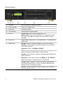
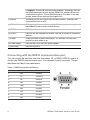
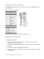
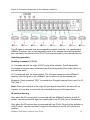
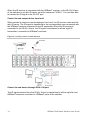
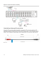
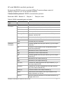
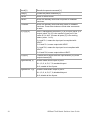
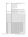
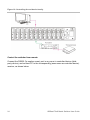
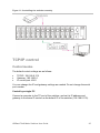
1
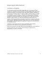
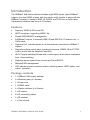
HDBaseT 8x8 Matrix Switcher User Guide Model CM-MT8810-BT-70 2014-02-516 • Rev 02 Copyright © 21MAR14 Clare Controls, Inc. All rights reserved. This document may not be copied in whole or in part or otherwise reproduced without prior written consent from Clare Controls, Inc., except where specifically permitted under US and international copyright law. Trademarks and patents HDBaseT 8x8 Matrix Switcher, Model CM-MT8810-BT-70 name is a trademark of Clare Controls, Inc. Other trade names used in this document may be trademarks or registered trademarks of the manufacturers or vendors of the respective products. Manufacturer Version Contact information Clare Controls, Inc. 7519 Pennsylvania Ave., Suite 104 Sarasota, FL 34243, USA This document applies to HDBaseT 8x8 Matrix Switcher Model CM-MT8810-BT-70 Rev 01. For contact information, see www.clarecontrols.com. Content Important information...iii Limitation of liability...iii Introduction...1 Features...1 Package contents...1 Front panel...2 Rear panel...3 Connecting with the RS232 communication port...4 Twisted pair cable connection...5 System connection...5 Usage precautions...5 Connecting with the HDBaseT extender set receiver...6 System diagram...7 Connection procedure...8 System applications...8 System operations...8 I/O control...8 Learn EDID data...9 EDID setting...9 Status check...10 Clear operation...11 IR control...11 IR remote...12 IR operations...12 IP and RS232 control protocol...17 Control the switcher...21 TCP/IP control...25 Control modes...25 USB firmware updating...28 HDBaseT 8x8 Matrix Switcher User Guide i Specifications...29 Dimensions...31 Troubleshooting and maintenance...31 Safety operation guide...32 After-sales service...33 ii HDBaseT 8x8 Matrix Switcher User Guide Important information Limitation of liability To the maximum extent permitted by applicable law, in no event will Clare Controls, Inc. be liable for any lost profits or business opportunities, loss of use, business interruption, loss of data, or any other indirect, special, incidental, or consequential damages under any theory of liability, whether based in contract, tort, negligence, product liability, or otherwise. Because some jurisdictions do not allow the exclusion or limitation of liability for consequential or incidental damages the preceding limitation may not apply to you. In any event the total liability of Clare Controls, Inc. shall not exceed the purchase price of the product. The foregoing limitation will apply to the maximum extent permitted by applicable law, regardless of whether Clare Controls, Inc. has been advised of the possibility of such damages and regardless of whether any remedy fails of its essential purpose. Installation in accordance with this manual, applicable codes, and the instructions of the authority having jurisdiction is mandatory. While every precaution has been taken during the preparation of this manual to ensure the accuracy of its contents, Clare Controls, Inc. assumes no responsibility for errors or omissions. HDBaseT 8x8 Matrix Switcher User Guide iii Introduction The HDBaseT 8x8 matrix switcher includes eight HDMI inputs, eight HDBaseT outputs, four local HDMI outputs, and four stereo audio outputs. It works with the HDBaseT receiver to transmit HDMI, IR, RS232, and POC over a Cat5e cable. Transmission distance can be up to 70 meters. Features Supports 1080P at 60 Hz and 3D. HDCP compliant, supporting HDMI 1.4a Powerful EDID&HDCP management. 8 HDBaseT outputs, to transmit HDMI, IR and RS232 to 70 meters over a Cat5e cable. Supports PoC, provides power for all the receivers connected to HDBaseT outputs. Supports multiple control ways, including front panel, RS232, IR and TCP/IP control (works with the Network Controller). IR OUT signal switching follows with a video signal, which can be separated from video switching. Supports remote control from receiver by IR and RS232. Multiple EDID management LCD indicator shows connection status, switching status, HDCP status, and output resolution. Package contents 1 x HDBaseT 8x8 matrix switcher 2 x Mounting ears (6 x Screws) 1 x Power cord 1 x RS232 cable 4 x Plastic cushions (4 x Screws) 1 x IR remote 8 x IR converting cables 1 x IR receiver 1 x User manual HDBaseT 8x8 Matrix Switcher User Guide 1 Front panel (1) Firmware Micro USB port for updating firmware. (2) Power indicator Power 'on' indicator light. (3) IR receiver IR receive window. (4) LCD indicator Shows real-time system status. (5) INPUTS Normal mode: Input buttons range from 1 to 8. Inquire mode: Press and hold SELECT for 3 seconds to enter this mode. Press ◄► to change menus and ▲▼ to change channels. (6) OUTPUTS Output buttons range from 1 to 8. HDMI INPUT 5 - 8 support local HDMI output. (7) FUNCTION GLOBAL: Select all outputs to transfer on input to all outputs. Example: Transfer both AV and IR signals from input channel 1 to all output channels. Operation: Press 1 + GLOBAL + SELECT. EDID: Management button. Enable input port to manually capture and study the EDID data of output devices. Example: Input channel 2 captures and studies the EDID data of output channel 4. Operation: Press buttons in this order EDID + 2 + 4 + SELECT. Note: Press button 2 in INPUTS and 4 in OUTPUTS. CLEAR: Clear an operation, such as switching output channel, studying EDID data before it comes into effect. Meanwhile, the switcher returns to the previous state. SELECT: Confirm operation. Press and hold it for 3 seconds to enter the Inquire mode. 2 HDBaseT 8x8 Matrix Switcher User Guide Rear panel (1) INPUTS a. IR OUT: Connect with IR transmitter, eight in total, to send out the IR signal from the HDBaseT port of the far-end Receiver. These IR OUTs make up an IR switcher with the IR INs on the HDBaseT receivers, and all can be switched synchronously with the AV signal, or separately switching. b. HDMI: HDMI input ports, eight in total, type A female HDMI connector, connect with HDMI input source devices. (2) OUTPUTS c. IR IN: Connect with IR receiver, fixed IR input for the output, cannot be switched separately. It makes up an IR bi-directional transmission with the IR OUT on the corresponding HDBaseT receiver. d. RS232: RS232 port to communicate with the RS232 port on corresponding HDBaseT receiver. When controlled by HDBaseT receiver, the communication protocol must be the same with the switcher. e. AUDIO: HDMI de-embedded stereo audio output f. HDMI: HDMI output port, connect with HDMI output devices. To split HDMI output for local monitoring. g. COAX: HDMI digital de-embedded audio output (ports 5 - 8). HDBaseT 8x8 Matrix Switcher User Guide 3 h. HDBaseT: Works with receivers using HDBaseT technology, such as the HDMI twisted pair receiver and the HDMI POC twisted pair receiver. It can pass through AV, IR, and RS232 signals to 70 meters. It can also provide power for the receivers that support PoC. (3) RS232 The serial port for unit control, 9-pin female connector, connects with control device such as a PC. (4) IR ALL IN IR control signal input port, connect with IR receiver, pass through to all the HDBaseT ports to control remote devices. (5) TCP/IP TCP/IP port for unit control. (6) IR EYE Connect with the extended IR receiver. Use the IR remote to control the switcher. (7) Power Press the button to power the switcher. The indicator turns red and remains on when power is on. (8) Power supply Connect with 110 to 240 VAC power adapter. (9) GROUND Connect to ground. Connecting with the RS232 communication port You can control the switcher from the front panel, IR, or RS232. RS232 control is via the rear RS232 communication port. It is a female 9-pin D connector. The pin definitions are listed in the table below. Table 1: RS232 connection definitions No. Pin Function 1 N/u Unused 2 Tx Transmit 3 Rx Receive 4 N/u Unused 5 Gnd Ground 6 N/u Unused 7 N/u Unused 8 N/u Unused 9 N/u Unused 4 HDBaseT 8x8 Matrix Switcher User Guide Twisted pair cable connection The cables for HDBaseT ports must be straight-thru using the T568B standard, as shown below. Table 2: T568B cable standards TIA/EIA T568B Pin Cable color 1 orange white 2 orange 3 green white 4 blue 5 blue white 6 green 7 brown white 8 brown 1st Ground 4-5 2nd Ground 1-2 3rd Group 3-6 4th Group 7-8 Note: RJ45 EZ connectors should not be used at any time. System connection Usage precautions The system should be installed in a clean environment with the property temperature and humidity controls. All of the power switches, plugs, sockets, and power cords should be insulated for safety. All devices should be connected before powering on. The Cat5e terminations for HDBaseT devices should be a straight-thru TIA/EIA T568B standard. HDBaseT 8x8 Matrix Switcher User Guide 5 Connecting with the HDBaseT extender set receiver The switcher can work with the HDBaseT extender set receiver to extend transmission distance up to 70 meters. Connect the HDBT output port of switcher to the receiver with a CaTx cable. Since the port supports PoC, once the switcher is powered on, the receiver will be powered synchronously. This allows the two devices to receive power with the same adapter. Figure 1: The HDBaseT extender set receiver (1) IR IR receiver. (2) ON Working status indicator of this device. When the TX70 transmitter is on and working properly, the green LED blinks. (3) LINK HDBaseT link status indicator, green LED. Remains illuminated when there is a connection. (4) OUT The LED remains illuminated when connected with devices that support HDCP, and the HDCP handshake is working normally. If the devices do not support HDCP, this green LED blinks. (5) POWER LED The red LED illuminates and stays illuminated when power is connected. (6)HDBT IN Connects via single Cat5e cable to the HDBaseT port in the TX70 transmitter or the switcher. (7) HDMI OUT: Connect to the HDMI display device. 6 HDBaseT 8x8 Matrix Switcher User Guide (8) IR IN: Connects to an IR receiver. The IR signal received from this port is transmitted via HDBaseT to the transmitter unit for use at the source location. Note: When an IR receiver connects to this port, the front IR port (1) is unavailable. (9) IR OUT: IR signals received by the TX70 transmitter or switcher and sent via HDBaseT to the RX70 receiver are available for emitter use from this port. (10) RS232: RS232 connector. Supports bi-directional RS232 communication. (11) 24V DC: Connects to the power supply. Not required when using PoC supplied by the TX70 transmitter or switcher. System diagram HDBaseT 8x8 Matrix Switcher User Guide 7 Connection procedure 1. Connect the HDMI sources (e.g., DVD) to the HDMI inputs of the switcher using HDMI cables. 2. Connect the HDMI displayers (e.g., HDTV) to the HDMI outputs of the switcher using HDMI cables. 3. Connect amplifiers or AVRs to the AUDIO output ports (3p captive screw connectors). 4. Connect the HDBaseT port of receiver and the switcher with a twisted pair. 5. Connect the RS232 port (9 pin female D) of the switcher with a control device (e.g., PC). 6. Connect the RS232 port of controlled device to any other RS232 port (3p captive screw connector) of the switcher. The control signal can be transmitted bi-directionally. 7. The switcher can be controlled through its built-in IR receiver, or through the IR EYE port connected with an external IR receiver. The IR signal can also be transmitted bi-directionally (connect IR OUT port to the IR IN port of other farend IR device, and connect the IR IN ports to the IR OUT port of other far-end IR device). Note: The IR IN port has built-in infrared carrier receiver. 8. Connect the 100 to 240 VAC power to the switcher. System applications The switcher is useful in any scenario when an HDMI signal (along with control signals) must be transmitted reliably across greater distances than is practical using traditional HDMI cables. It can be used in both residential and commercial applications when centrally locating the source equipment and displaying HD video in remote locations. The switcher allows the sharing of source content across multiple displays. System operations The button operation examples are showed in “Front panel” on page 2. Here we make a brief introduction to the system inquire operations. I/O control Convert an input to an output. Example: Input 1 to output 2. 8 HDBaseT 8x8 Matrix Switcher User Guide Operation: Press 1 + 2 + SELECT Note: In default status, eight IR OUTs are corresponding with eight HDM INPUTS. When you convert an HDMI input to an output, IR OUT switches synchronously. Convert an input to many outputs. Example: Convert input channel 2 to output 2, 4, 7. Operation: Press 2 + 2 + 4 + 7 + SELECT Convert an input to all. Example: Convert Input 1 to all outputs. Operation: Press 1 + GLOBAL + SELECT Note: Each button flashes three times, and then extinguishes. Should the operation fail, the light extinguishes immediately. Learn EDID data Learn EDID data from one input port to one output port. Example: Enable input 2 to learn EDID data from output 4. Operation: Press EDID + 2 + 4 + SELECT All input ports learn EDID data from one output port. Example: Enable all input ports to learn EDID data from output 4. Operation: Press EDID + GLOBAL + 4 + SELECT Note: Each button flashes two times when the data is successfully copied, and then extinguishes. Should the operation fail, each button flashes quickly for 3 seconds. EDID setting Select one type of EDID data from following four types of built-in EDID data: INPUT 1: 1080P 2D PCM2.0 INPUT 2: 1080P 3D 5.1 INPUT 3: 1080P 2D PCM2.0 INPUT 4: 1080P 2D 5.1 HDBaseT 8x8 Matrix Switcher User Guide 9 To set the EDID data of one input port, press EDID and hold for 3 seconds to enter in EDID setting statues, and then press INPUTS + OUTPUTS + SELECT. Example: Set the EDID data of INPUT 4 to the forth type of EDID data. Operation: Press EDID + 4 + 4 + SELECT To set the EDID data of all input ports, press EDID and hold for 3 seconds to enter in EDID setting statues, and then press GLOBAL + OUTPUTS + SELECT. Example: Set the EDID data of all input ports to the second type of EDID data. Operation: Press EDID + GLOBAL + 2 + SELECT Note: Each button will flash for two times when the data copies successfully, and then extinguishes. Should the operation fail, each button quickly flashes for 3 seconds. Status check To access the System Inquire menu, press SELECT for 3 seconds. Use the left and right direction buttons to navigate checking previous and next item. Table 3: Examples of front panel operations Function items Example Description Check the connection status of inputs Y means the corresponding port is connected with input device. N means it is not. Check the connection status of outputs Y means the corresponding port is connected with output device. N means it is not. Correspondence between inputs and outputs Shows the correspondence between the eight inputs and eight outputs. Check if the input is with HDCP Y means the input signal is with HDCP. N means it is not. Check if the output is with HDCP Y means the output signal is with HDCP, N means it is not. Check the output resolution Use ▲▼ to check all eight output resolutions. 10 HDBaseT 8x8 Matrix Switcher User Guide Output check Press any output button to check the corresponding input. Example: Check which one is the corresponding input to output 2. Operation: Press output 2 button. The LCD screen display “01B02 01R02”, and the indicators for input 1 and output 2 turn on for 3 seconds. Output 2 corresponds with input 1. Clear operation When you switch output channels, study EDID data, or set EDID data, press CLEAR to clear the operation before you press SELECT to enable it. When pressed, the switcher returns to the previous status. IR control Using IR and HDBaseT transmission technology, the switcher has the following functions. Control far-end output device from local Control local input and output device remotely Control the switcher locally or remotely Note: Non-flashing emitters are not supported You can control the switcher using its built-in IR receiver, or through the IR EYE port by connecting it to an extended IR receiver. Or, you can control it remotely using an IR device though the twisted pair. HDBaseT 8x8 Matrix Switcher User Guide 11 IR remote Figure 2: IR remote (1) Standby Press to enter or exit Standby mode (2) Input buttons 1 to 8, IR signal switched to the corresponding HDMI signal. (3) Menu buttons ALL (GLOBAL), EDID and CLEAR buttons have the same function as those on the front panel. (4) Direction buttons Up, Down, Left, Right, Enter to confirm. (5) Output buttons 1 to 8, IR signal switched to the corresponding output signal. IR operations IR matrix switching The eight “IR OUT” ports make up an 8x8 IR switcher with the eight “IR IN” ports of the far-end receivers, as shown below. 12 HDBaseT 8x8 Matrix Switcher User Guide Figure 3: Control local devices or the switcher remotely The IR signal is received from a corresponding remote controller. It is transferred to HDBaseT receiver, then to corresponding zone of the switcher through the twisted pair, and finally transferred to the IR OUT port and received by the controlled device. Switching operation Sending command: [x1]R[x2]. x1: Corresponds with the eight IR OUT ports of the switcher. The IR transmitter connected to this port can be placed at the IR receiving area of the output device or the switcher itself. x2: Corresponds with the zone number. The IR signal transmits to the HDBaseT receiver, and then goes to the HDBaseT port of this zone via the twisted pair. Example: Send command “3R2.” to transfer the IR signal received from zone 2 to IR OUT port 3. Note: When you switch all of the eight IR input signal channels to the same IR out channel, it is not able to control the all controlled device(s) at the same time. IR carrier enforcing Only when the IR receiver that is connected with the HDBaseT receiver is with IR carrier, can the received IR signal be transferred to the IR OUT port of the switcher. Only when the IR receiver that is connected with the IR ALL IN port of the switcher is with IR carrier, can the received IR signal be transferred to the IR OUT port of the switcher. HDBaseT 8x8 Matrix Switcher User Guide 13 When the IR receiver is connected with the HDBaseT receiver, or the IR ALL IN port of the switcher is not with IR carrier, send the command “%0901.” You are then able to transfer the IR signal to the IR OUT port. Control far-end output device from local When needed to control a remote displayer from local, the IR receiver used must be with IR carrier. The IR signal is transferred to the corresponding zone connected with the HDBaseT receiver connected to the IR transmitter. When the IR receiver is connected to the IR ALL IN port, the IR signal is transferred to all the eight IR transmitters connected to HDBaseT receivers. Figure 4: Locally control remote devices Control far-end device through IR ALL IN port The IR signal received from the IR ALL IN port is transmitted to all the eight far-end HDBaseT receivers connected to HDBaseT ports of the switcher. 14 HDBaseT 8x8 Matrix Switcher User Guide Figure 5: Control remote devices through IR ALL IN port Control local device from remote User can control local device remotely, such as video source device, switcher, etc. When in use, the IR signal received from the HDBaseT receiver is transmitted to the corresponding IR OUT port of the switcher. HDBaseT 8x8 Matrix Switcher User Guide 15 Figure 6: Control local devices remotely Controlled by a third-party IR control device Using the IR converting cable (included), connect the 3P end to the switcher’s IR input port, and then connect the 2P end to the IR output port of the third-party control device. The IR signal is transmitted via the twisted pair to the remote output device. 16 HDBaseT 8x8 Matrix Switcher User Guide IP and RS232 control protocol Bi-directional RS232 to each connected HDBaseT receiver allows control of displays, projectors, etc. at the receiver locations. Communication protocol: RS232 communication protocol Baud rate: 9600 Data bit: 8 Stop bit: 1 Parity bit: none Table 4: RS232 command types and codes Command Type Command Code Function System Command /*Type; Returns the switcher model information. /%Lock; Lock the front panel buttons on the switcher. /%Unlock; Unlock the front panel buttons on the switcher. /^Version; Returns the firmware version installed. /:MessageOff; Turn off the feedback command from the COM port. It displays “switcher OK”. /:MessageOn; Turn on the feedback command from the com port. Demo. Puts the switcher into 'Demo' mode. Undo. Cancels the prior command. [x]All. Transfer signals from the input channel [x1] to all output channels All#. Transfer all input signals to the corresponding output channels respectively. All$. Switches off all the output channels. All@ Switches on all the output channels. [x]#. Transfer signals from the input channel [x] to the output channel [x]. [x]$. Switches off the output channel [x]. [x]@. Switches on the output channel [x]. [x1] V[x2]. Transfer the video signal from the input channel [x1] to the output channel [x2]. [x1] B[x2]. Transfer the AV and IR signals from the input channel [x1] to the output channel [x2]. Status(X) Check the status of the output channel [x]. Status. Returns the current status of the input channel to the output channels one by one. Save[Y]. Saves the present operation to the preset command [Y], ranges from 0 to 9. Operation Command HDBaseT 8x8 Matrix Switcher User Guide 17 Recall[Y]. Recalls the preset command [Y]. Clear[Y]. Clears the preset command [Y]. PWON. Work in normal mode. PWOFF. Enter into standby mode and end power to HDBaseT receivers. STANDBY Enter into standby mode and keep power to HDBaseT receivers. Press other buttons or send other commands to start. /%[Y]/[X]:[Z]. HDCP management command. [Y] is for input (value: I) or output (value: O). [X] is the number of one port, if the value of X is ALL, it means all ports. [Z] is for working status (value: 1 or 0). Y=I and Z=1, means the input port is compliant with HDCP. Y=O and Z=1, means output with HDCP. Y=I and Z=0, means the input port is not compliant with HDCP. Y=O and Z=0, means output without HDCP. [x1] R[x2]. Transfer the IR signal from the input channel [x1] to the output channel [x2]. DigitAudioON[ x]. Enable HDMI audio output of port x. X=1, 2, 3, 4, 5, 6, 7, 8, enable this port. X=9, enable all the 8 ports. DigitAudioOF F[x]. Disable HDMI audio output of port x. X=1, 2, 3, 4, 5, 6, 7, 8, disable this port. X=9, disable all the 8 ports. 18 HDBaseT 8x8 Matrix Switcher User Guide /+[Y]/[X]:******. Set communication between PC and HDBaseT Receiver. Y is for port. Y = 1, 2, 3, 4, 5, 6, 7, or 8, means to send the command in a given baud rate to the corresponding HDBaseT receiver. Y = 9, means to send the command to all connected HDBaseT receivers. Y = A, B, C, D, E, F, G, or H, means to send the command to the corresponding HDBaseT receiver only when in normal mode. Y = E, F, G or H, means to send the command to the corresponding HDBaseT receiver only when in standby mode. X is for baud rate. Value ranges from 1 to 7. 1 = 2400, 2 = 4800, 3 = 9600, 4 = 19200, 5 = 38400, 6 = 57600, and 7 =115200) ***** is for the data (max 48 Byte) The symbol “.” is the end of one command. If there are some symbols with “.” in one command, then this case is allowed and the last one is the end of this command. EDIDH[x]B[y]. Study the EDID from output port [x] to input port [y]. If the EDID data is effective and the audio portion does not support PCM mode, then force-set it to support PCM mode only. If the EDID data is not effective, then set it as initialized EDID data. EDIDPCM[x]. Set the audio portion of input port [x] to PCM format in the EDID database. EDIDG[x]. Get EDID data from the output port and display the output port number of X. EDIDMInit. Recover the factory default EDID data. EDIDM[X]B[Y]. Manual EDID switching. Enable input [Y] to study the EDID data of output [X]. If the EDID data is not effective, then set it as initialized EDID data. EDIDUpgrade [x]. Upgrade EDID data via the RS232 port. [X] is for input port, when the value of X is 9, it means to upgrade all input ports. When the switcher receives the command, it will show a message to prompt you to send EDID file (.bin file). Operations are canceled after 10 seconds. End all connections of HDBaseT ports. HDBaseT 8x8 Matrix Switcher User Guide 19 UpgradeIntED ID[x]. Select one type of EDID data and upgrade built-in EDID data. Supports 4 types of EDID data: 1. 1080P, 2D, PCM2.0 2. 1080P, 2D, 5.1 (audio) 3. 1080P, 3D, PCM2.0 4. 1080P, 3D, 5.1 (audio) [x] = 1, 2, 3 or 4 When the switcher receives the command, it displays a message to send the EDID file (.bin file). Operations are canceled after 10 seconds. 20 EDID/[x]/[y]. Set the built-in EDID data of input port [x] to type [y]. The value of [y] is 1, 2, 3, and 4. The EDID data types are the same as mentioned above. %0801. Automatic HDCP management. %0900. Set as infrared carrier following mode. %0901. Set as infrared carrier enforcing mode. %0911. Reset to factory default. %9951. Check the command sent by port 1 when PWON. %9952. Check the command sent by port 2 when PWON. %9953. Check the command sent by port 3 when PWON. %9954. Check the command sent by port 4 when PWON. %9955. Check the command sent by port 5 when PWON. %9956. Check the command sent by port 6 when PWON. %9957. Check the command sent by port 7 when PWON. %9958. Check the command sent by port 8 when PWON. %9941. Check the command sent by port 1 when PWOFF. %9942. Check the command sent by port 2 when PWOFF. %9943. Check the command sent by port 3 when PWOFF. %9944. Check the command sent by port 4 when PWOFF. %9945. Check the command sent by port 5 when PWOFF. %9946. Check the command sent by port 6 when PWOFF. %9947. Check the command sent by port 7 when PWOFF. %9948. Check the command sent by port 8 when PWOFF. %9961. Check the system locking status. %9962. Check the status while in standby mode. HDBaseT 8x8 Matrix Switcher User Guide %9963. Check the working mode of infrared carrier. %9964. Check the IP address. %9971. Check the connection status of the inputs. %9972. Check the connection status of the outputs. %9973. Check the HDCP status of the inputs. %9974. Check the HDCP status of the outputs. %9975. Check the switching status. %9976. Check the output resolution. %9977. Check the status of digital audio of output channels. %9978. Check the HDCP status of the input ports. Notes Disconnect all the HDBaseT cables before sending the command EDIDUpgrade[X]. In above commands, the [ ] symbols are for easier reading and do not need to be typed in the actual operation. Remember to end the commands with the ending symbols “.” and “;”. Type the command carefully. It is case-sensitive. Control the switcher To control the switcher, you must connect its 9-pin female RS232 port to the PC’s RS232 port, or you can just connect any one of the HDBaseT receiver’s RS232 ports to the PC. The RS232 command transmits to the switcher via the twisted pair. Use the RS232 control software to control the switcher. HDBaseT 8x8 Matrix Switcher User Guide 21 Figure 7: Controlling the switcher locally Figure 8: Controlling the switcher remotely 22 HDBaseT 8x8 Matrix Switcher User Guide Control third-party device from local Connect the 9-pin female RS232 port in the switcher with the PC. Use the RS232 command “/+[Y]/[X]:******.” to control the third-party device connected to the HDBaseT receiver. Figure 9: Controlling a third-party device locally Bi-directional RS232 control By connecting one 3p captive screw RS232 port with the PC (or controlled device), and then connecting the RS232 port of corresponding HDBaseT receiver with the controlled device (or PC), the RS232 signal can be transmitted bi-directionally. Control far-end device from local Connect the RS232 (3P captive screw) port in any zone to the PC, and then connect the controlled RS232 device (third-party device) to the corresponding receiver (same zone as the PC), as shown below. HDBaseT 8x8 Matrix Switcher User Guide 23 Figure 10: Controlling far-end device locally Control the switcher from remote Connect the RS232 (3p captive screw) port in any zone to controlled device (thirdparty device), and connect PC to the corresponding (same zone as controlled device) receiver, as shown below 24 HDBaseT 8x8 Matrix Switcher User Guide Figure 11: Controlling the switcher remotely TCP/IP control Control modes The default control settings are as follows: TCP/IP: 192.168.0.178 Gateway: 192.168.0.1 IP control port: 4001 You can change the IP and gateway settings as needed. Do not change the serial port number. Control by a single PC Connect a computer to the TP port of the switcher, and set its IP address and gateway to the same IP section as the default IP of the switcher (192.168.0.178). HDBaseT 8x8 Matrix Switcher User Guide 25 Figure 12: Setting the PC’s IP address the same as the switcher Control by PC(s) in LAN You can connect the switcher can to a router to make up a LAN with the PC(s) so that it can be controlled in a LAN. Ensure the switcher’s IP section is the same as the router. Figure 13: Connecting to a LAN 26 HDBaseT 8x8 Matrix Switcher User Guide To connect to a LAN: 1. Connect the TCP/IP port of the switcher to Ethernet port of PC using a Cat5e cable. 2. Set the PC’s IP address and gateway to the same IP section as the switcher. Note the PC’s original IP address and gateway. 3. Set the switcher’s IP address and gateway to the same IP section as the router. 4. Set the PC’s IP address and gateway as the original one. 5. Connect the switcher and PC(s) to the router. In the same LAN, each PC is able to control the switcher asynchronously. TCP/IP settings 1. Connect the TCP/IP port of the switcher to Ethernet port of PC with twisted pair. 2. Set the PC’s IP and gateway to the same IP subnet as the default IP of the switcher (192.168.0.178). 3. Launch your web browser, and then enter 192.168.0.178. This is the default IP address for all Clare Controls HDMI switchers. 4. When the Web Interface Login page displays, enter the user name “clareadmin” and password “secure7”, and then click Login. 5. Select the Network tab and set the following parameters. IP address Subnet Gateway HDBaseT 8x8 Matrix Switcher User Guide 27 6. Click Save. 7. Reboot the switcher. Once rebooted, you will be able to control the switcher over IP. USB firmware updating To allow for future changes, or to add new functions, the switcher firmware switch can be upgraded via USB. To upgrade, download the latest upgrade file, and then upgrade it through the EXE software. Copy the EXE software to the PC, and then double-click the program to upgrade the firmware. Figure 14: Update EXE software When the program is running normally, it will enter into the interface (as shown in next figure). Click Open and choose the upgrade file downloaded, and then click Connect USB. The upgrade will begin. When complete, a window will appear showing the message “Update success.” 28 HDBaseT 8x8 Matrix Switcher User Guide Figure 15: Interface of update EXE software Note: The COM number connected with PC is available only when in 1 to 9. Specifications Video Input Video Output Input 8 HDMI Output 4 HDMI 8 HDBaseT Input connector Female HDMI Output connector Female HDMI female RJ45 (with LED indicators) Input level T.M.D.S. 2.9 V / 3.3 V Output level T.M.D.S. 2.9 V / 3.3 V Input impedance 100Ω (differential) Output impedance 100Ω (differential) HDBaseT output Up to 70 m 1080P to 60 Hz, Cat5e Video general Gain 0 dB Bandwidth 6.75 Gbit/s Video signal HDMI (or DVI-D) Maximum pixel clock 225MHz Resolution range Switching Speed Up to 1920 × 1200 at 60 Hz or 1080P at 60 Hz 200ns (max.) Transmission distance 70 m with POC 1080P at 60 Hz EDID management In-built EDID data and manual EDID management HDCP Supports HDCP 1.3, auto and manual HDCP management HDBaseT output resolution Audio General Output signal Stereo audio Digital audio HDBaseT 8x8 Matrix Switcher User Guide Output connector 8 3p captive screw connectors 29 Stereo output Earphone output distortion: 0.1% 32Ω / 70 mW at 1 KHz, 0.1% 16Ω / 105 mW to 1 KHz Coax output Supports PCM, Dolby, DTS 5.1 Frequency response 20 Hz to 20 KHz CMRR > 90 dB at 20 Hz to 20 KHz 8 IR OUTs (green) 8 IR INs (black) Panel control Front panel buttons TCP/IP control Works with the network controller V2.2 Control ports Control ports 1 IR EYE (black) 1 TCP/IP (female RJ45) 1 RS232 (9 pin female D) 8 RS232s (3p captive screw connectors) IR Default IR remote Extend IR EYE General Power supply 110 to 240 VAC Power consumption Full load: 117.8 W, Floating: 54.4 W Case dimension (W × H × D) 17.3 × 3.5 × 14.9 (44.0 × 8.8 × 38.0 cm) Weight 12.3 lb. (5.6 Kg) Temperature -4 to +158ºF (-20 to +70ºC) 30 HDBaseT 8x8 Matrix Switcher User Guide Dimensions Troubleshooting and maintenance When there is a color losing or no video signal output, the cables may be broken or are not well connected. When EDID management does not work normally, the HDMI cable may be broken at the output end. When switching, there is a blank screen on the displayer, the displayer may not support the resolution of the video source. Switch again or manage the EDID data manually to make the resolution of the video source automatically comply with the output resolution. When a user cannot control the switcher by computer through its COM port, check the COM port number in the software. Make sure the COM port is in good condition and the communication protocol is correct. When switching and there is no output image: Check that there is a signal at the input and the output. Check if the output port number is the same with the controlled one. Check that the input/output cables are not broken, nor the connectors are loose. Try another cable. It is not uncommon for any switcher device to experience trouble when learning 3D EDID signal from a source device, such as a Blu-ray player. If your switcher cannot learn the 3D EDID signal, connect the source device directly to the display device (TV) and play the movie. Once the movie begins playing, reconnect the source device to the switcher and relearn the EDID data. HDBaseT 8x8 Matrix Switcher User Guide 31 Safety operation guide To guarantee the reliable operation of the equipment and safety of the staff, please follow the procedures listed below. The system must be grounded properly. Do not use two blades plugs. Ensure the supply voltage is in the correct range of 100 to 240 V and from 50 to 60 Hz. Do not locate the device in a place that is abnormally hot or cold or does not have proper temperature control and ventilation. The device generates heat when running. Its environment should be well ventilated to prevent damage caused by overheating. Disconnect power in humid weather, or when left unused for long periods. Before making or removing any connections to the device, ensure that the power supply has been disconnected. Do not attempt to open the enclosure of the equipment. Do not attempt any repairs. There are no user-serviceable parts inside. Any attempt to open the equipment will result in a complete void of any warranty and may result in serious injury or death. Do not splash any chemical substances or liquids on or around the equipment. 32 HDBaseT 8x8 Matrix Switcher User Guide After-sales service If there appears to be problems when running the device, refer to the “Troubleshooting and maintenance” section in this manual. Return shipping costs are not covered by this warranty. You can contact Customer Support at http://support.clarecontrols.com. Please be ready to provide the following information. Product model number, version and serial number. Detailed description of the trouble issues. Description of all connections and third-party equipment being used. We offer this product with a three-year warranty, which starts from the first day you purchase this product. If, during the warranty period, the unit cannot be repaired, a suitable replacement will be issued. Replacement units will be comparable to the original. However, due to potential design changes over time, replacement units may not be identical to the unit replaced. Items not covered by this warranty. Damage caused due to incorrect usage and/or connections. Damage caused due to installation by person(s) not adequately trained in the installation of this equipment. Any attempt to open this unit and access internal components shall immediately void this warranty. Damage caused by any physical force (dropping the unit or dropping an object upon the unit, etc.). Damage caused by voltage/cycle fluctuations outside acceptable range. Damage caused by over-current, voltage spikes or lightning damage due to inadequate surge protection. A valid invoice of purchase via an authorized dealer shall be required for any warranty coverage. HDBaseT 8x8 Matrix Switcher User Guide 33