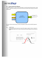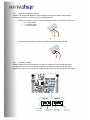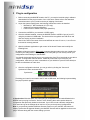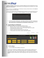
1
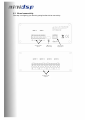
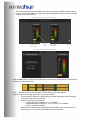
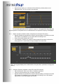
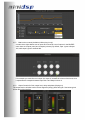
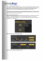
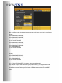
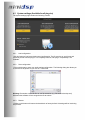
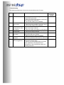
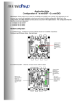
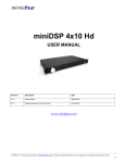
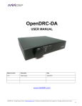
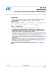
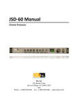
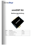
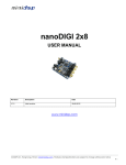
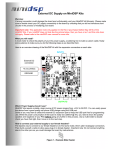
miniDSP Balanced 2x4
USER MANUAL
V1.0
Revision
Description
Date
V1.0
User manual – Initial version
24-12-2010
Table of content
1
2
System setup ..............................................................................................................................3
miniDSP Basics ..........................................................................................................................4
2.1 What is a miniDSP? ..............................................................................................................4
2.2 miniDSP programming..........................................................................................................4
2.3 Board connectivity.................................................................................................................5
2.4 Typical connection diagram ..................................................................................................6
2.4.1
minDSP Power .............................................................................................................6
2.4.2
Audio Input/Output connectivity ...................................................................................7
2.4.3
Sensitivity Jumpers ......................................................................................................7
3 Plug-in configuration ...................................................................................................................8
4 Typical plug-in architecture.........................................................................................................9
4.1 Audio settings .......................................................................................................................9
4.1.1
Inputs and RMS meters (Available in all plug-ins) .......................................................9
4.1.2
High and Low pass filters (Available in Mixer, 2way Xover, 4way plugins) ...............10
4.1.3
Graphic equalizer (Available in Mixer, 2way/4way Xover Graphic EQ version) ........11
4.1.4
Parametric Equalizer (Available in 2way PEQ, 4way PEQ versions) ........................11
4.1.5
Matrix mixer controls (Available in Mixer plug-in only)...............................................12
4.1.6
Output Controls for Gain, output level, delay and phase (All plug-ins) ......................12
4.1.7
Advanced Plug-in features .........................................................................................13
4.1.8
Room EQ Wizard (REW) integration (Advanced software only)...............................14
4.2 System settings (Available for all plug-ins) .........................................................................15
4.2.1
Load configuration:.....................................................................................................15
4.2.2
Save configuration......................................................................................................15
4.2.3
Restore.......................................................................................................................15
1
System setup
Minimum System Requirements for software installation
MiniDSP controller software runs in a PC environment with the following minimum requirements.
Software
•
•
•
•
Microsoft• ® Windows® Vista® SP1/ XP pro SP2
Microsoft• ® .NET framework v3.5
Adobe AIR environment (latest version)
Adobe Flash player (latest version)
Hardware
•
•
•
•
PC with 1GHz or higher processor clock speed recommended / Intel®
Pentium®/Celeron® family, or AMD K6®/AMD Athlon®/AMD Duron® family, or compatible
processor recommended.
256 megabytes (MB) of RAM or higher recommended
USB 2.0 port
Keyboard and mouse or compatible pointing device
Package content
Your miniDSP Balanced 2x4 package includes:
• 1 x miniDSP balanced 2x4 in an aluminum enclosure with keyhole mounts
• 1 x miniUSB cable
• All plug-in terminal block connectors required for audio inputs, outputs and DC power
• Step by Step startup guide
Not included in the package but required for normal operation
•
1 x 12VDC external DC supply with at least 150mA
Disclaimer / Warning
An incorrect miniDSP configuration could easily damage your audio system. MiniDSP can not be
responsible for any damage that may result from the improper use of this device. As with any other
product, we do recommend that you carefully read the manual and other technical notes to insure
you fully understand how to operate the board.
As a general guideline, you should first configure your miniDSP board before connecting anything
to the outputs of the MiniDSP (loudspeakers/other output sources). Doing so will make sure that
you have the software correctly configured and won’t cause any damage to your system. Once
again, miniDSP can not be responsible of any damages the board make cause to your system.
Finally, MiniDSP is a very flexible board and 99% of typical questions we receive at the tech
support department are already answered in this user manual. So please take the time to carefully
read this user manual. Thanks for your understanding!
2 miniDSP Basics
Before diving into the details of this board, it is important for you to fully understand what a
miniDSP does and how it can be useful to the setup of your audio system. The following section
will highlight basic concepts of a miniDSP.
2.1
What is a miniDSP?
miniDSP is a Digital Audio Signal Processor capable of performing a wide range of applications,
from filtering, equalization, muting, time alignment etc… The control of the device is performed
from a software application, so called a plug-in, which provides control of the board settings over
USB. Only one plug-in can run on a miniDSP board at a time and only one miniDSP board can be
controlled at a time.
2.2
miniDSP programming
A good part of the success of the miniDSP concept lies in its simplicity of use. Here are the typical
steps required to program a miniDSP.
- Connect the board to your PC/Mac machine
- Launch the plug-in, by default in off-line mode and allowing you to configure settings as
required.
- The next step is to “Connect & Synchronize” your PC to the board, i.e. flashing the
configuration you just have in your plug-in and going to the On-line mode.
- Once the board synchronized, you will be in what the so called “On-line mode”, i.e. able to
hear the effect on real time changes to the settings. No further “Synchronization” to the
board is required since all settings from now on are saved to both the DSP and the Flash
component of the device for long term memory.
- Once happy with your configuration, simply un-plug the board and the audio configuration
will run as last modified in on-line mode. No need for a PC connection from now on since
the board will boot up every-time with that configuration.
Now that you have a basic understanding of how things work, let’s get down to the details.
2.3
Board connectivity
First step in configuring your board is getting familiar with its connectivity.
Analog Audio
inputs
USB 2.0 for
Control only
Analog Audio
Outputs
+12V Power
supply input
2.4
Typical connection diagram
The following diagram is a typical connectivity diagram for a basic setup with analog inputs, analog
outputs. To prevent any damage, make sure the board is turned OFF before doing any connection
modifications.
From Audio
Source
From PC USB
MiniDSP
Balanced 2x4
To OUTPUTS
Active loudspeakers,
A/V receiver,
Multi-channel amplifier,
Recording devices
etc…
+12V DC
For more information about 2way or 3/4 way configurations, please consult miniDSP Application
section.
2.4.1
•
minDSP Power
miniDSP Balanced 2x4 requires an external DC supply to operate correctly. A single 12V
DC @ 200mA power source must be connected to the Power supply connector as shown
below.
12VDC (+)
Ground (-)
2.4.2 Audio Input/Output connectivity
miniDSP can accept both balanced and un-balanced audio inputs/outputs. See the below
instructions for audio connectivity on your miniDSP Balanced.
•
Balanced connection (In/Out): Follow connectivity as shown on underside of the board.
o S = > Cable Shield
o + = > Positive cable
o - = > Return cable
S
•
-
+
Un-balanced inputs/outputs: Note how a jumper is required between S and -
+
-
2.4.3 Sensitivity Jumpers
miniDSP Balanced 2x4 input sensitivity can easily be modified to fit your needs. By default
configured for 2Vrms, you can open the enclosure to modify the jumper setting. See below
diagrams for more info on how you can modify the input sensitivity with a single jumper change..
Input 1
High sensitivity
Max 0.9Vrms
Low Sensitivity
Max 2Vrms
Input 2
High sensitivity
Max 0.9Vrms
Low Sensitivity
Max 2Vrms
3 Plug-in configuration
1. Before connecting the MiniDSP board to the PC, you need to install the plug-in software
downloaded from the plug-in section of our online store. Please refer to the download
instructions sent to you by email on the day of shipping of the board.
2. As per the system requirements, the following frameworks need to be installed:
o Microsoft• ® .NET framework v3.5 (PC only)
o Adobe AIR environment (Mac/Win)
o Latest version of Adobe Flash player (Mac/Win)
3. Connect the miniDSP to your external +12VDC supply.
4. Once the software installed, connect the MiniDSP board to a USB 2.0 port of your PC,
using the provided mini USB cable. The device will be recognized as a HID driver and
does not require any driver installation.
Note: A blue LED in the center of the board will flash at a rate of 1sec on, 1 sec off once
the board is correctly powered.
5. Open the software application to gain control of the board. Please read carefully the
following lines:
By default, all plug-ins start in offline mode, meaning changes made on the user interface do
not affect your configuration. It is designed in such a way that you can visually confirm your
configuration before loading it to the MiniDSP.
You should also know that plug-ins can only synchronize from PC to board and are not able to
“retrieve” a configuration from the device. It basically means that if you really like your
configuration, make sure you save it somewhere on your hard drive (more to follow below) to
be able to reload them at a later time.
6. Once the configuration checked, you can go online by clicking the “Connect &
Synchronize” button as shown below.
Synchronize
Providing your board is connected to the PC with a USB cable, the following important dialog
box pops up with 4 options:
a) Synchronize: With this option, the current plug-in configuration will be loaded/flashed to the
MiniDSP and your plug-in turned to “On-line” mode. Warning that it will overwrite whatever
configuration was previously loaded on the board. If you’d like to load a different configuration,
click cancel and go to the settings tab to load one of your previously saved configurations.
Note: If you previously installed a different firmware version on your miniDSP, this button will
display: Synchronize & Upgrade. Meaning, the MiniDSP firmware will be upgraded to the current
plug-in firmware along with the current settings you have.
b) Restore to Default: With this option, the software application resets all settings back to factory
default and reload the firmware. Warning that all current settings will be lost and there are no ways
to be able to recover them.
c) If in any doubt, click the Help button to refresh your memory on these choices or click Cancel to
be able to go back to the offline mode.
In either synchronization steps, the following dialog box will pop-up. It’s very important that you do
not un-plug the board in the middle of a firmware upgrades or you may corrupt the configuration.
7. Once the board fully synchronized, a “Successful connection to the board” message pops
up. From this point on, all changes to the configuration will be real time and live, therefore
giving you the chance to hear the effect of your equalization, filtering, tuning…
4 Typical plug-in architecture
Depending on your plug-in, the software is organized as below:
•
•
•
•
•
Main tab: Gives you access to Audio or System settings sections
Synchronize button: Allows you to go online and gain control of your system
Audio Mute: Mute all inputs & outputs
Help link: A quick link to get back to the main help page
Control toolbar: Click to access controls of each audio algorithm
Connect &
Synchronize
Main Tab
Master Mute
Help link
Control toolbar
4.1
Audio settings
4.1.1
Inputs and RMS meters (Available in all plug-ins)
The first step in configuring your MiniDSP consists in making sure audio is being fed to the
input correctly. To do so, click on the button labeled “inputs”. The RMS meter will quickly
indicate the average value of the input signal in dBFS (i.e. relative to the full scale of the ADC
or 24bit I2S signal). Individual faders control the digital gain at the input and per channel mute
status.
This meter displays dB full scale (dBFS) values and will saturate at 0dBFS for about 0.9Vrms
mode or 2Vrms mode. Make sure to keep the signal below 0dBFS (red color) and with enough
headroom to prevent distortion.
Screenshot of Input window for 2way/Mixer plug-ins
Per channel
mute button
dBFS input
meter.
Per channel
Level control
Next Page
Screenshot of Input window for 4way plug-ins
Click the Next button to switch windows OR click one of the control toolbar buttons. A darker color
indicates the current active tab.
4.1.2 High and Low pass filters (Available in Mixer, 2way Xover, 4way plugins)
Controls for the Low and High pass filters are very much similar.
• Cut off frequency: Select the -3dB frequency by either entering the value or using the
up & down arrows of the numeric box.
• Choose one of the three filter types:
o Linkwitz Riley (LR): Available in 12, 24, 48dB/oct
o Butterworth (BW): Available in 6, 12, 18, 24, 30, 36, 42, 48dB/oct
o Bessel: Available in 12dB/oct
Each filter has different phase and amplitude characteristics. We recommend you to
look online for more information about the specifics of each filter.
•
Bypass button allows you to disable the filter (Enabled by default). Make sure to
bypass the filter if you do not need a low pass filter.
The log scale graph gives you the equivalent response of the applied filter. By pointing the
mouse anywhere on the plotted curve, the dB attenuation and respective frequency are displayed.
4.1.3
Graphic equalizer (Available in Mixer, 2way/4way Xover Graphic EQ version)
•
•
•
Bypass: Disables the equalization but doesn’t reset the settings. A handy tool to check
the influence of equalization on your system without resetting to zero
Reset: Sets all boost faders back to zero
Link channels: If enabled, any change on either graphic EQ channels is reflected on
both graphic EQ. A useful feature to apply changes to the stereo field.
Note: The log graph displays the combined effect of low pass filter, equalization and high pass
filtering.
4.1.4
Parametric Equalizer (Available in 2way PEQ, 4way PEQ versions)
•
•
•
EQ band selection: Select one of the 6 x Parametric equalizers
Filter type: Select between Peak, Low Shelf, High Shelf
Bypass: Disables the equalization but doesn’t reset the settings. A handy tool to check
the influence of equalization on your system without resetting to zero. Note that the
bypass button is per-band Bypass (not overall).
4.1.5 Matrix mixer controls (Available in Mixer plug-in only)
A matrix mixer object allows a set of inputs to be mixed to a set of outputs. In the MiniDSP
case, there are 2 inputs (rows) and 4 outputs (columns). By default, Input 1 goes to Output
1&3, while input 2 goes to channel 2&4.
If for example you would like to mix input 2 to output 4, increase the volume of this knob, since
it represents the crosspoint between Input Row 2 and Output column 4.
4.1.6 Output Controls for Gain, output level, delay and phase (All plug-ins)
The output section will allow control of time alignment (delay), phase and gain. See below typical
screen shot of the interface.
4.1.7 Advanced Plug-in features
For those of you wishing to experiment with your custom filter programming, miniDSP provides an
easy interface for custom biquad programming. A lot of readily available information can be found
online and the reader shouldn’t expect this user manual to provide the basics about biquad
programming. For more info, google “Biquad filters”, “digital filters”, “eq cookbook”…
The advantage of the Advanced mode remains the flexibility miniDSP provides in allowing you to
build any custom filter (e.g. cascade filter, Linkwitz transform, high order filters…etc) with a simple
programming user interface as shown below.
How to use the advanced mode:
First and foremost, you will need understand that biquad coefficients can represent a wide range
of filters (e.g. LPF/HPF/PEQ/high shelv…etc). Using the biquad calculator, you can easily
calculate these coefficients without the need of any external software. Building a cascaded filter
configuration is a child’s play! ☺
PEQ interface for basic vs Advanced mode:
Filter interface for basic vs Advanced mode:
Note: In the filter mode, the software interface expects the 8 biquads to be filled in such format:
biquad1,
b0=0.000042324375459811486,
b1=0.00008464875091962297,
b2=0.000042324375459811486,
a1=1.975933280159253,
a2=-0.9761025776610925,
biquad2,
b0=0.000042324375459811486,
b1=0.00008464875091962297,
b2=0.000042324375459811486,
a1=1.975933280159253,
a2=-0.9761025776610925,
.
.
.
.
biquad8,
b0=0.000042324375459811486,
b1=0.00008464875091962297,
b2=0.000042324375459811486,
a1=1.975933280159253,
a2=-0.9761025776610925
4.1.8 Room EQ Wizard (REW) integration (Advanced software only)
Also available uniquely for the Advanced biquad product series is the integration with REW
software. By combining a measurement software with our miniDSP, it basically allows custom
biquad filters generated by the AutoEQ function of REW to be inputted inside the miniDSP
software. For more information, please consult the REW software user manual and EQ device
section.
4.2
System settings (Available for all plug-ins)
The system settings page contains the following controls.
4.2.1 Load configuration:
Use this feature to load a previously saved configuration. The file must be as .xml format and
previously saved from this plug-in. For complexity reasons, inter-plug-in compatibility is not
available.
4.2.2 Save configuration
Click on this button to save your audio settings configuration. The following dialog box allows you
to save the file anywhere on your PC as a .xml format.
Warning: Remember to save the file as .xml file extension. (e.g. file saved as backup.xml)
Otherwise the software will not recognize the file at restore.
4.2.3 Restore
Clicking on this button will restore the board back to factory default. All settings will be lost during
this process.
Troubleshooting
The following symptoms were found to be the most likely cause of issues.
Item#
Symptoms
Troubleshooting recommendation
1
No audio on outputs
2
No audio on RMS
input meters
3
Audio on input RMS
meters but no audio
on outputs
Cannot reload
configuration
Cannot connect to
the board
- Make sure that some audio signal is showing
on the RMS input meters.
- Double check that input & output mute buttons
are not greyed out (mute ON)
- Confirm that master mute is disabled
- Check your connectivity
- Double check the strength of your input signal.
- Confirm that master mute is disabled
- Make sure the matrix mixer is set to send
audio to the output channels
- Check the output mute status for each channel
- Confirm the file format of your file (.xml)
- Confirm the version of the file
- If using external DC supply, try connecting the
board with USB power instead
- Make sure the blue LED is illuminated
- Confirm that you installed the required
frameworks (Adobe Air/ Microsoft .net / SP2 XP)
- Have a look at our forums to see if someone
else already had this issue.
- Send us an email ([email protected]) with a
clear explanation of the symptoms and
descriptions of the troubleshooting steps you
already performed
4
5
6
10
Cannot install
software
Problem unsolved by
above suggestions
If not
solved go
to item
3
10
10
10
10
10
n/a