1
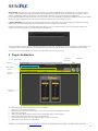
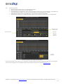
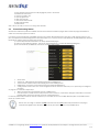
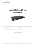
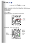
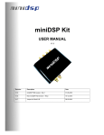
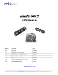
nanoDIGI 2x8
USER MANUAL
Revision
Description
Date
V1.0
Initial revision
28-06-2012
www.minidsp.com
miniDSP Ltd – Hong Kong / Email : [email protected] / Features and Specifications are subject to change without prior notice
P1
Contents
1
2
Product Introduction.............................................................................................................................................................................................. 3
System Connectivity .............................................................................................................................................................................................. 5
2.1
Board connectivity ......................................................................................................................................................................................... 5
2.2
Typical setup.................................................................................................................................................................................................... 5
2.2.1
DC Power connectivity ....................................................................................................................................................................... 6
2.2.2
Audio connectivity .............................................................................................................................................................................. 6
2.2.3
IR control ............................................................................................................................................................................................... 6
3
Software Setup........................................................................................................................................................................................................ 7
4
Plug-in Architecture ............................................................................................................................................................................................... 8
4.1.1
Main Page............................................................................................................................................................................................. 8
4.1.2
Preset Memory selection .................................................................................................................................................................... 9
4.1.3
Input Tab ............................................................................................................................................................................................... 9
4.2
Matrix Tab......................................................................................................................................................................................................... 9
4.3
Output Tab..................................................................................................................................................................................................... 10
4.3.1
Custom Label ..................................................................................................................................................................................... 10
4.3.2
Monitor................................................................................................................................................................................................. 10
4.3.3
Output volume ................................................................................................................................................................................... 11
4.3.4
Crossover............................................................................................................................................................................................. 11
4.3.5
Parametric Equalizer.......................................................................................................................................................................... 12
4.3.6
Compressor /Limiter........................................................................................................................................................................... 13
4.3.7
Master volume control ...................................................................................................................................................................... 13
4.4
Load/Save/Restore a configuration .......................................................................................................................................................... 13
4.4.1
Load configuration:........................................................................................................................................................................... 13
4.4.2
Save configuration ............................................................................................................................................................................ 13
4.4.3
Restore Factory default .................................................................................................................................................................... 13
4.4.4
Restore Factory default .................................................................................................................................................................... 13
4.5
Firmware upgrade ........................................................................................................................................................................................ 13
4.6
IR remote learning feature .......................................................................................................................................................................... 14
5
Troubleshooting .................................................................................................................................................................................................... 15
miniDSP Ltd – Hong Kong / Email : [email protected] / Features and Specifications are subject to change without prior notice
P2
1 Product Introduction
nanoDIGI 2x8 is a Digital Audio Signal Processor (DSP) capable of performing a wide range of applications, from filtering, equalization
to time alignment. Typically located between an audio source (CD player/Receiver/Preamp/PC .. etc) and the amplifier, a miniDSP
will provide unparalleled tuning flexibility to improve your audio system’s performance. Using a PC/Mac machine and a USB
connection, you will be able to control your platform from the “plug-in”: an intuitive software application allowing real time
modification to your configuration.
Besides its audio specs, a great part of our product concept lies in its simplicity of use. The sequence of steps required to control a
miniDSP can be summarized as follow:
Connect the board to your PC/Mac machine using a USB cable
Launch the plug-in to configure settings as required.
Click “Connect & Synchronize” your PC to the board
Once synchronized, any change is real time and does not require any “Synchronization”. All settings are also automatically
saved to both the DSP and the Flash for long term memory.
Once happy with your configuration, you can disconnect the board from your computer since from this point on, the audio
configuration will run as last modified in on-line mode and recalled following every reboot.
Enjoy!
Minimum System Requirements for software installation
MiniDSP software requires in a PC/MAC environment with the following minimum requirements:
PC Environment
PC with 1GHz or higher processor clock speed recommended / Intel® Pentium®/Celeron® family, or AMD K6®/AMD
Athlon®/AMD Duron® family, or compatible processor recommended.
512 megabytes (MB) of RAM or higher recommended
USB 2.0 port
Keyboard and mouse or compatible pointing device
Microsoft• ® Windows® Vista® SP1/ XP pro SP2/Win7
Microsoft• ® .NET framework v3.5
Adobe AIR environment (latest version)
Adobe Flash player (latest version)
MAC Environment
Intel based MAC with 1GHz or higher processor clock speed recommended
512 megabytes (MB) of RAM or higher recommended
USB 2.0 port
Keyboard and mouse or compatible pointing device
Mac OSX 10.4 or higher
Adobe AIR environment (latest version)
Adobe Flash player (latest version)
Package content
Your miniDSP package includes:
•
1 x nanoDIGI 2x8 Hd
•
1 x USB cable 1m long
•
1 x 5VDC universal power supply interchangeable plug
•
1 x Step by Step startup guide
miniDSP Ltd – Hong Kong / Email : [email protected] / Features and Specifications are subject to change without prior notice
P3
DISCLAIMER / WARNING
An incorrect miniDSP configuration could easily damage your audio system. MiniDSP can not be responsible for any damage that
may result from the improper use of this product. As with any other product, we do recommend that you carefully read the manual
and other technical notes to insure you fully understand how to operate the board.
As a general guideline, you should first configure your miniDSP board before connecting anything to the outputs of the MiniDSP
(loudspeakers/other output sources). Doing so will insure that you have the software correctly configured and won’t cause any
damage to your system. Once again, miniDSP can not be responsible of any damages the board make cause to your system.
Finally, MiniDSP is a very flexible board and 99% of typical questions we receive at the tech support department are already
answered in this user manual. So please take the time to carefully read this user manual. Thanks for your understanding!
WARRANTY TERMS
miniDSP Ltd warrants all our products to be free of from defects in materials and workmanship for a period of one year from the
invoice date. Our warranty terms do not cover failure of the product due to an external trigger, misuse, servicing or usage outside of
the recommended use. With this said, make sure to carefully read the user manual when customizing the board. Any board damage
investigated as failure to follow proper installation may void the warranty. So if in doubt, please make sure to contact us first.
miniDSP Ltd – Hong Kong / Email : [email protected] / Features and Specifications are subject to change without prior notice
P4
2 System Connectivity
2.1
Board connectivity
Reset
IR receiver
SPDIF input (RCA)
Toslink
receiver(Optical)
SPDIF Outputs1-4
miniUSB
DC input (5-24VDC)
White LED
2.2
Typical setup
The following diagram is a typical system & connectivity diagram in a configuration with 4 x external SPDIF DAC device. To prevent
any damage, make sure the board is turned OFF before doing any connection modifications.
miniDSP Ltd – Hong Kong / Email : [email protected] / Features and Specifications are subject to change without prior notice
P5
SPDIF Stereo DAC
SPDIF/Toslink Source
SPDIF Stereo DAC
nanoDIGI 2x8 K
SPDIF Stereo DAC
USB 2.0 for control
SPDIF Stereo DAC
Being an all digital platform, the nanoDIGI only interfaces to SPDIF/Toslink digital audio interface.
2.2.1
DC Power connectivity
nanoDIGI 2x8 requires a single 5VDC supply to operate. A universal SMPS power supply is already provided along with the unit.
Here is a picture of the power supply provided along with the plugs.
2.2.2
Audio connectivity
The nanoDIGI 2x8 can accept 2 types of digital audio connectivity for input. While the input is selectable to one of the source (via
remote/software), all outputs are enabled and outputting the processed digital signal.
Input Signal
Connector
SPDIF
RCA connector – Unbalanced connector
Toslink
Optical connector
Output Signal
Connector
SPDIF
RCA connector – Unbalanced connector
2.2.3
IR control
The nanoDIGI 2x8 is controllable via a wide range of Infrared Remote. Instead of adding yet another remote to your “stack”, our
engineering team implemented a learning IR feature allowing control from any Sony/Nec/Philips remote. Please read the learning IR
process from the software section of this user manual.
IR receiver
miniDSP Ltd – Hong Kong / Email : [email protected] / Features and Specifications are subject to change without prior notice
P6
3 Software Setup
miniDSP platforms are controlled and configured over a USB connection. Our software, so called plug-in, must be purchased from our
online webstore separately. The following section will highlight the steps required to configure the miniDSP plug-in.
In order to familiarize yourself with the software first, do not connect any
amplifiers to your miniDSP outputs until you understand each object.
Get to know the software first, then start playing audio…
1.
The first step consists in downloading the following required frameworks:
o
Microsoft• ® .NET framework v3.5 or up (PC only)
o
Latest version of Adobe AIR environment (Mac/Win)
o
Latest version of Adobe Flash player (Mac/Win)
2.
Next, go to the User Downloads section of the miniDSP website. The purchased plug-in will be
available for download once logged in with the credentials for your account.
3.
Double click on the .air file to install the plug-in. The following dialog box will pop up.
Once the configuration finalized, the plug-in will automatically boot up.
4.
You can now connect the miniDSP board to one of the USB 2.0 port of your PC. The device will be recognized as a HID driver
and does not require any driver installation.
5.
The next step is to gain control of the board by synchronizing the PC configuration to the board. Please read carefully the
following section to understand how this process works.
By default, all plug-ins start in offline mode, meaning changes made on the user interface do not affect your configuration. It is
designed in such a way that you can visually confirm your configuration before loading it to the MiniDSP kit.
You should also know that plug-ins can only synchronize from PC to board and are not able to “retrieve” a configuration from the kit.
In other words, make sure your favorite configuration is saved on your PC if you ever decide to change the configuration.
6.
Once the configuration checked, the next step is to “Connect & Synchronize” by clicking on the Green button on the top
right. Note that this button is ONLY active in an unconnected mode. Once connected, it will disappear since no more
synchronization will be required from there on.
Connect & Synchronize
Providing your board is connected to the PC with a USB cable, the following important dialog box pops up with 4 options:
miniDSP Ltd – Hong Kong / Email : [email protected] / Features and Specifications are subject to change without prior notice
P7
a) Synchronize: With this option, the current plug-in configuration will be loaded/flashed to the MiniDSP and your plug-in turned to
“On-line” mode. Warning that it will overwrite whatever configuration was previously loaded on the board. If you’d like to load a
different configuration, click cancel and go to the settings tab to load one of your previously saved configurations.
If you previously installed a different firmware version on your kit, this button will display: Synchronize & Upgrade. Meaning, the MiniDSP
kit firmware will be upgraded to the current plug-in firmware along with the current settings you have.
b) Restore to Default: With this option, the software application resets all settings back to factory default and reload the firmware.
Warning that all current settings will be lost and there are no ways to be able to recover them.
In either synchronization steps, the following dialog box will pop-up. It’s very important that you do not un-plug the board in the
middle of a firmware upgrades or you may corrupt the configuration.
Once the board fully synchronized, a “Successful connection to the board” message pops up. From this point on, all changes to the
configuration will be real time and live, therefore giving you the chance to hear the effect of your equalization, filtering, tuning…
Let’s move on to the architecture of the software to understand how to setup your system.
4 Plug-in Architecture
4.1.1
Main Page
Connect &
Synchronize
Master Mute
Main Menu
Preset Memory
selection
Main Tab
selection
Main control
window
Main input page for the nanoDIGI 2x8 plug-in
The main control page can be summarized in few core sections.
•
File Access to Load/Save configuration
•
Restore: Access to restore the whole system or only the current selected configuration (preset)
•
Help: Link to the help file
•
Main control tab: Allows selection between input, matrix and output control windows
•
Main control window: Contains controls for the selected tab
•
Synchronize button: Allows you to go online and gain control of your system
•
Master Mute: Mute all inputs & outputs signal
miniDSP Ltd – Hong Kong / Email : [email protected] / Features and Specifications are subject to change without prior notice
P8
4.1.2
Preset Memory selection
The nanoDIGI 2x8 Hd allows the user to create up to 4 preset memories for a quick reconfiguration of the processor. Under each
configuration, all settings of the platform are saved.
Placed at the top of the user interface, the use of configurations couldn’t be easier. Simply toggle between configurations by clicking
on the config button. The currently selected configuration
WARNING: By toggling configurations, you may go from a working configuration (i.e. correct volume/setup/Eq) to an unknown
(or improperly configured) configuration. We therefore recommend that you perform a quick configuration offline (without
being connected/synchronized to the processor) to prevent any damage to your equipment.
4.1.3
Input Tab
The first step in configuring your MiniDSP consists in making sure audio is being fed to the input correctly. To do so, click on the button
labeled “inputs”. The RMS meter will quickly indicate the average value of the input signal in dBFS (i.e. relative to the full scale of the
ADC or 24bit I2S signal). Individual faders control the digital gain at the input and per channel mute status.
This meter displays dB full scale (dBFS) values and will saturate at 0dBFS (full scale of the ADC). Do make sure to keep the signal below
0dBFS (red color) and with enough headroom (say 10dB) to prevent saturation during the typical audio peaks of a music source.
Source selection
Custom
Label
Per channel
monitoring
Per channel
Level control
Per channel
PEQ button
Per channel
mute button
4.2
Matrix Tab
The matrix DSP object is the DSP object linking inputs to outputs. While very typical on commercial DSP products, it may be new for
some of you. The following section will summarize the basics of configuration.
Matrix switchers work as a “matrix” where:
Rows are inputs
Columns are outputs
And the status(ON/OFF) of the buttons at the crosspoint of rows (inputs) & columns (outputs) will define the routing and
mixing of the audio to one of 8 outputs. .
The following configuration shows how the matrix should be configured for a 4way configuration with:
Left audio input being routed to analog outputs 1-4
Right audio input being routed to analog outputs 5-8
miniDSP Ltd – Hong Kong / Email : [email protected] / Features and Specifications are subject to change without prior notice
P9
Crosspoint
buttons (ON)
Digital outputs in
Columns
Digital inputs in
Rows
Note how labels of input channels and output channels followed on the Matrix mixer to simplify your routing.
Let’s illustrate the concept of configuration of this block using a 3way configuration + 2 subs where both Left & Right signals are being
mixed (combined).
Mixing happens when
multiple crosspoints are
enabled within a column
4.3
Output Tab
Master volume
control
Custom label
Monitor
Output volume
Crossover control
PEQ control
Mute control
Polarity control
Compressor/limiter
Output delay
4.3.1
Custom Label
The custom label feature allows you to input a user defined label for each output channels: A handy feature to remember the output
configuration of your system.
4.3.2
Monitor
Allows you to monitor the input meter of that specific channel on a RMS meter. Note that the information is shown in dBFS
miniDSP Ltd – Hong Kong / Email : [email protected] / Features and Specifications are subject to change without prior notice
P 10
4.3.3
Output volume
A fader control for +12 to -70dB digital gain control. Similar to the input volume control.
4.3.4
Crossover
Controls for the Low& High pass filters are available when clicking on the Xover (crossover) button:
The log scale graph gives you the equivalent response of the applied filter. By pointing the mouse anywhere on the plotted curve, the
dB attenuation and respective frequency are displayed.
Linking Features
High Pass Filter
settings
•
•
•
•
Low Pass Filter
settings
Cut off frequency: Select the -3dB frequency by either entering the value or using the up & down arrows of the numeric
box.
Filter types:
o
Linkwitz Riley (LR): Available in 12, 24, 48dB/oct
o
Butterworth (BW): Available in 6, 12, 18, 24, 30, 36, 42, 48dB/oct
o
Bessel: Available in 12dB/oct
Each filter has different phase and amplitude characteristics. We recommend you to look online for more information
about the specifics of each filter.
Bypass button allows you to Enable/Disable the filter. Make sure to bypass the filter if you do not need the filter enabled.
Linking feature allows you to link real time the settings of two crossover windows: a handy feature for stereo
environments requiring synchronized changes to both left and right channels.
Step 1: Select the channel you would like to link to from the drop down menu. The linking feature will link these two channels together.
Step 2: Click on the “Link” tick box to enable the linking.
Note that the environment will warn you that all current PEQ settings of the current channel will be copied over to the linked channel.
At anytime during the operation, you can decide to “unlink” the channels by simply clicking on the “link” tick box.
miniDSP Ltd – Hong Kong / Email : [email protected] / Features and Specifications are subject to change without prior notice
P 11
4.3.5
Parametric Equalizer
•
•
•
•
•
EQ band selection: Select one of the 6 x Parametric Equalizers
Filter type: Select between Peak, Low Shelf, High Shelf
Bypass: Disables the equalization but doesn’t reset the settings. A handy tool to check the influence of equalization on
your system without resetting to zero. Note that the bypass button is per-band Bypass (not overall).
Linking feature: Similar to the crossover dialog box, you can link up two EQ settings together.
Basic/Advanced radio button: Toggles from basic mode (i.e. input frequency) to advanced custom biquad input.
Toggle from basic
to Advanced
Select the
filter type
EQ band selection
Per Band
bypass EQ
Basic mode
Per Band
bypass EQ
Advanced mode for custom biquad programming
The Advanced mode can be used for your custom filters of external software such as Room EQ Wizard (REW). For more information
about the auto-tuning feature of the miniDSP, please check miniDSP’s website for the following application note.
miniDSP Ltd – Hong Kong / Email : [email protected] / Features and Specifications are subject to change without prior notice
P 12
4.3.6
Compressor /Limiter
Typical Comp/Limiter settings
Comp/ Limiter metering
shows real time amount of
attenuation by comp/limiter
Comp/ Limiter chart
Bypass Comp/ Limiter
A compressor/Limiter allows dynamic range compression of the signal to prevent damage of your speakers. Extensive information is
available online on the use of compressor/limiter. Please take the time to familiarize yourself with such processing block before
using it.
4.3.7
Master volume control
The master volume control allows control of all 8 outputs channels of the unit unit. It is controlled from the IR commands.
4.4
4.4.1
Load/Save/Restore a configuration
Load configuration:
Use this feature to load a previously saved configuration. The file must be as .xml format and previously saved from this plug-in. For
complexity reasons, inter-plug-in compatibility is not available.
4.4.2
Save configuration
Use this feature to save your audio settings configuration. The following dialog box allows you to save the file anywhere on your PC as
a .xml format. All 4 memory preset configurations will be saved.
4.4.3
Restore Factory default
Use this feature to restore the board back to factory default. Warning that all configurations will be restored back to default from this
action.
4.4.4
Restore Factory default
Use this feature to restore the board back to factory default. Warning that settings of all four configurations will be blanked back to
default.
4.5
Firmware upgrade
In order to enable some new features, the miniDSP may require to be flashed with a new firmware. All the required tools
and firmware files are already included in the in the installation folder of the plug-in. So the first step to make sure you
have everything you need is to install the new plug-in by logging to the UserDownload section. Note that firmware
upgrade tools is Windows only at this point of time. A mac tool is in the works.
A warning may be shown during synchronization if you have the incorrect firmware loaded on your platform.
Once the new plug-in installed, please browse to \\Program Files\MiniDSP\MiniDSP-8x8\firmware_tools\Windows. Three files can be
found there:
- Upgrade steps
- Upgrade Tool executable
- Firmware file
The firmware upgrade summarizes to few simple steps:
1. Unplug the DC power
miniDSP Ltd – Hong Kong / Email : [email protected] / Features and Specifications are subject to change without prior notice
P 13
2. Press and hold the reset button while pluging the power to the board
3. Release the reset button
4. Connect the USB to the
5. Open Upgrade Tool
6. Click Open Hex File
7. Choose the lastest hex file
8. Click Program/Verify
9. Reset Device
That’s all. You’re ready to move on to using a new firmware.
4.6
IR remote learning feature
This feature is enabled on platforms enabled with the correct firmware and latest plug-in. Please check the plug-in information to
make sure it currently supports the feature.
In an effort to keep the platform compatible with the most common IR standards and not ask users to add another remote to your
pile, we implemented an IR learning feature. This feature allows you to use any remote compatible with the NEC/Philips RC6 and Sony
IR standards. Learning an IR commands goes as follow:
1) Connect & synchronize the board to the newly downloaded plug-in
2) Under the new “IR Remote Plug-in”, click on the “IR Learning menu” to reach the following dialog box.
3) Ten commands are available for control from a remote. They include:
Master mute
Volume Up: 1dB increments with ramping down when holding button
Volume Down: 1dB decrements with ramping down when holding button
Digital Source 1/2 used for source selection between Toslink and SPDIF input.
Config 1/2/3/4: Used to select one of the config built under the software. Make sure you’ve previously pre-configured
these first!
To program a command, 2 simple steps:
•
While connected and synchronized: Press the “LEARN button”
•
Point the remote to the IR receiver and press the button to learn the command. A dialog box will confirm a successful
learning and a green arrow appears once the command learned.
In case the platform fails to learn the remote command, you most likely do not have a Philips RC6/Sony/Nect compatible remote.
Please try another remote.
•
•
•
•
•
Feature such as Config 1-4 selection will only work when the unit is not connected/synchronized to the plug-in.
Command for Digital source selection is for future only and does not apply to any miniDIGI setup.
miniDSP Ltd – Hong Kong / Email : [email protected] / Features and Specifications are subject to change without prior notice
P 14
5 Troubleshooting
The following symptoms were found to be the most likely cause of issues.
Item#
1
Symptoms
No audio on outputs
2
No audio on RMS input
meters
3
Audio on input RMS
meters but no audio on
outputs
Cannot reload
configuration
Cannot connect to the
board
4
5
6
Cannot install software
7
Software running in
background but not
showing
Problem unsolved by
above suggestions
10
Troubleshooting recommendation
- Make sure that audio signal is shown on the RMS input
meters.
- Double check that input & output mute buttons are not
enabled
- Confirm that master mute is not enabled
- Confirm that you are synchronized and live
- Check your connectivity
- Double check the strength of your input signal.
- Confirm that master mute is disabled
- Make sure the matrix mixer is set to send audio to the output
channels in a mixer plug-in
- Check the output mute status for each channel
- Confirm the file format of your file (.xml)
- Confirm the version of the file
- Reset the board by powercycling the unit
- Make sure the unit is seen in the device manager as a HID
device
- Confirm that you installed the required frameworks (Adobe
Air/ Microsoft .net / SP2 XP)
- Adobe Air environment most likely requiring a version
update. Connect your PC to the Internet to automatically
get an update.
- Have a look at our forums to see if someone else already
had this issue.
- Send us an email ([email protected]) with a clear
explanation of the symptoms and descriptions of the
troubleshooting steps you already performed
If not solved go to item
3
10
10
10
10
10
10
n/a
miniDSP Ltd – Hong Kong / Email : [email protected] / Features and Specifications are subject to change without prior notice
P 15