1
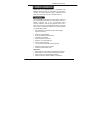
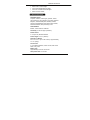
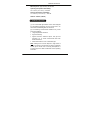
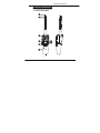
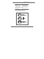
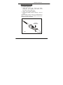
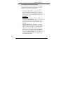
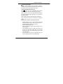
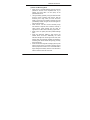
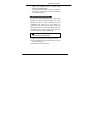
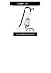
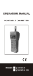
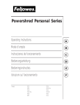
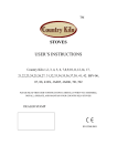
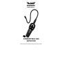
NGD8800 USER’S MANUAL COMBUSTIBLE GAS DETECTOR Please read this manual carefully and thoroughly before using this product. CONTENT Page 1. GENERAL INFORMATION ------------------ 2 2. FEATURES ----------------------------------------- 2 3. SPECIFICATIONS ------------------------------- 3 4. OPERATION GUIDE --------------------------- 4 5. PARTS & CONTROLS ---------------------- 5-6 6. GETTING STARTED -------------------------- 7 6-1 Installing Batteries ------------------------- 7 6-2 Automatic Circuit/Reset Feature ------ 8 6-3 Feature Sensitivity Adjustment -------- 9 7. OPERATING PROCEDURES --------- 9-12 8. REPLACING NEW SENSOR ------------- 12 9. CLEANING --------------------------------------- 13 COMBUSTIBLE GAS DETECTOR 1. GENERAL INFORMATION Thank you for purchasing this Combustible Gas Detector. Read though the instruction manual before operation for correct and safe usage. Please store and retain this instruction manual for future reference. 2. FEATURES This Combustible Gas Detector is extremely useful as a general purpose tool in any environment where propane, methane, natural gas, gasoline and fuel oil is used. This unit uses a newly developed semi-conductor sensor which is extremely sensitive to variety of general use combustible gases. Microprocessor controlled with advanced digital signal processing Multi color visual display High-Low leak sensitivity selector Low battery indication Semiconductor gas sensor Detection of combustible gas Carrying case included 15.5 in. (400mm) flexible stainless probe Reference Leak source included Ambient concentration reset Application: Detect leaks in automobile exhaust and fuel system Detect leaks in liquid or gas fired heating systems Safety checks at propane filling stations Search for arson residue (detects accelerants) 2 COMBUSTIBLE GAS DETECTOR Detect fuel in marine bilges Check manholes/sewers for safety Check for cracked heat exchangers Detect solvent residue 3. SPECIFICATIONS Detectable Gases: Propane, methane, natural gas, gasoline, fuel oil, CH4 (methane), H2 (hydrogen), Iso-butane, Ethanol, Ethylene, Tetrachloroethylene, Dimethyl sulfide, Toluene, Folmaldehyde, Dietyl-ether, Ethyl-acetate, Dochloromethane, NH3 (ammonia), R-22 Alarm Method: Buzzer, Tricolor LED bar Indicator Sensitivity: As low as 5ppm (methane) Power Source: 4 “AA” (6V DC) alkaline batteries Probe Length: 15.5 in. (400mm) Dimension / Weight: 6.8 x 2.6 x 2.2 in. (173 x 66 x 56mm) / approximately 14.1 oz. (400g) Accessories: 4 “AA” alkaline batteries, user’s manual, leak check bottle, carry case Battery Life: Approximately 40 hours normal use Auto power OFF: 10 minutes 3 COMBUSTIBLE GAS DETECTOR Warm-Up Time: Approximately 90 seconds Operating Temperature & Humidity: 32° to 104°F (0° to 40°C), < 80% RH Storage Temperature & Humidity: 14° to 140°F (-10° to 60°C), < 70% RH Altitude: <6500 ft. (2000m) 4. OPERATION GUIDE (1) This combustible gas detector unit is NOT designed for anti-explosive measures. Do not use this unit in an area where combustible gases can be found. (2) The following environmental conditions may cause error in the readings: Large temperature variations High wind velocity Organic solvents, adhesive vapors, fuel gas and vesicants. Try to avoid environments filled with these substances. Places filled with too much combustible gas Note: Although this unit will respond to high levels of carbon monoxide, it should NOT be used as a detector for this gas in normal room or working atmospheres. It is used to pinpoint a leak as described in the operating instruction. 4 COMBUSTIBLE GAS DETECTOR 5. PARTS & CONTROLS 5-1 Panel Description COMBUSTIBLE GAS DETECTOR 9 ○ 5 COMBUSTIBLE GAS DETECTOR 1. Sensor 2. Sensor Protector 3. LED Leak Indicators 4. Sensitivity Lo Button 5. Sensitivity Hi Button 6. Low Battery Indicator 7. Power On/Off & Reset Button 8. Battery Cover 9. Battery Cover Screw 5-2 LED Leak Indicator Definition: 6 COMBUSTIBLE GAS DETECTOR 6. GETTING STARTED 6-1 Installing Batteries Loosen the screw and remove the battery compartment door located on the bottom of the instrument as shown below (Fig.1) Install 4 “AA” size alkaline batteries Reinstall the battery cover by aligning it with the handle When the battery power is running low, the Red LED Low Battery indicator illuminates. The batteries should be then replaced as quickly as possible. 4 “AA” size alkaline batteries Fig.1 7 COMBUSTIBLE GAS DETECTOR 6-2 Automatic Ambient Reset Feature This combustible gas detector features an Automatic Ambient Reset function that sets the unit to ignore ambient concentrations of combustible gas. Automatic Ambient Setup - Upon initial power on, the unit automatically sets itself (approx. 1.5 minutes) to ignore the level of combustible gases present at the tip. Only a level, or concentration, greater than this will cause an alarm. CAUTION! This feature will cause the unit to ignore any combustible gases present at power on. In other words, with the unit OFF if you place the tip up to a known leak and switch the unit on, NO leak will be indicated! Ambient Reset Feature - Resetting the unit during operation performs a similar function; it programs the circuit to ignore the level of combustible gases present at the tip. This allows the user to 'home-in' on the source of the leak (higher concentration). Similarly, the unit can be moved to fresh air and reset for maximum sensitivity. Resetting the unit with no combustible gas present (fresh air) causes any level above zero to be detected. 8 COMBUSTIBLE GAS DETECTOR 6-3 Feature Sensitivity Adjustment The Instrument provides two levels of sensitivity. When the unit is switched on, it is set to the high sensitivity level by default. To change the sensitivity, press the the key is pressed, the visual key. When display will momentarily show the two left LED's (green) indicating Low Sensitivity level is selected. To switch back to High Sensitivity, press the key. The two right LED's (red) will light momentarily indicating high Sensitivity level is selected. 7. OPERATING PROCEDURES WARNING! 1. Do not use the instrument in an area of extremely high level of combustible gas. 2. The gas/vapor of organic solvent might interfere with the function of the unit. During detection, please eliminate the influence of the organic solvent. 3. In order to ensure correct operation and indication, the unit should be switched on and warm-up in non-contaminated atmosphere. 9 COMBUSTIBLE GAS DETECTOR z How to Find Leaks NOTE: A sudden whipping of the leak detector probe or "blowing" into the sensor tip will affect the air flow over the sensor and cause the instrument to alarm. (1) Power-Up & Reset function key: The key turns the combustible leak detector instrument ON or OFF and is also the reset function. Press it once to turn on the combustible leak detector. The display will illuminate with flash, for 1.5 minutes to heat up the sensor. Press it again to reset the ambient base concentration. Press and hold this button for 5 seconds to turn OFF the power. (2) Verify the condition of the unit and sensor: Monthly testing of unit is recommended using the included reference leak source or when even it is suspected that the reading is not correct. Set the sensitivity level to “Hi”. Open the leak check bottle cover and slowly move it closer to sensor. If the indication moves up to high from low then you should move the check bottle away and the LED should go off again. This shows that the unit is under working condition. If the unit does not perform as expected, bring the unit for maintenance at your local sales office. 10 COMBUSTIBLE GAS DETECTOR (3) Enter the Measuring Mode Place the tip of the leak-detector probe as close as possible to the site of the suspected leak. Try to position the probe within 1/4 inch (6mm) of the possible leak source. Losing sensitivity gradually. Using the reference leak source to check: normally (new sensor), with the sensitivity set to high, when you move the check bottle to the sensor, the detector responds very fast (immediately detects the gas with full LED lights on and continuous beep). Older sensors: over time, sensor sensitivity drops and detection response time increases, whereby a newer sensor would activate the red LED, as opposed to an older sensor indicating a green LED. Slowly move the probe past each possible leakage point. When the instrument detects a leak source, the audible alarm will sound. Additionally, the visual indicators will light from left to right; Green LED, then Orange LED, then Red LED (highest concentration). Increasing LED levels indicate the growing proximity to the leak source. When the Instrument signals a leakage, pull the probe away from the leak for a moment, and then bring it back to pinpoint the location. If the combustible leak is large, setting the sensitivity switch to LOW will make it easier to find the exact site of the leak. 11 COMBUSTIBLE GAS DETECTOR Return the sensitivity switch to HIGH before searching for additional leaks. When finished leak testing, turn OFF the instrument and store it in a clean place. Protect the leak detector from possible damage. 8. REPLACING NEW SENSOR The sensor has a limited operative period. Under normal operation, the sensor should be replaced once a year. Exposing the sensor to high concentration of coolant (>30000ppm) will shorten its life cycle rapidly. It is important to make sure that sensor surface is free from water droplets, vapor, oil, grease, dust and all other forms of contaminants. For proper operation, the sensors must be replaced annually or when contaminated. WARNING! When replacing sensor, the worn-out sensor may be HOT!! (1) Remove cone cap cover from the tip of the probe. (2) Pull out old sensor and insert the new sensor into the plug (see below fig.2). (3) Seal the cap cover over the plug. 12 COMBUSTIBLE GAS DETECTOR Sensor protector Sensor Fig.2 9. CLEANING The Instrument plastic housing can be cleaned with standard household detergent or isopropyl alcohol. Care should be taken to prevent the cleaning fluid from entering the instrument. Gasoline and other solvents may damage the plastic and should be avoided. WARNING! Detergent or isopropyl alcohol may damage the sensor, please keep them away from the sensor during the cleaning process. 13 GENERAL TOOLS & INSTRUMENTS 80 White Street New York, NY 10013-3567 PHONE (212) 431-6100 FAX (212) 431-6499 TOLL FREE (800) 697-8665 e-mail: [email protected] www.generaltools.com NGD8800 User’s Manual Specifications subject to change without notice ©2010 GENERAL TOOLS & INSTRUMENTS Notice - we are not responsible for typographical errors. MAN#NGD8800 12/10