1
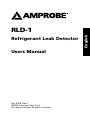
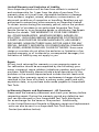
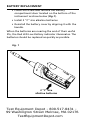
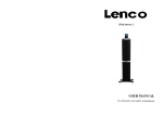
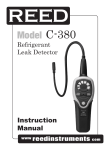
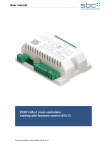
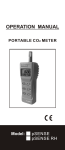
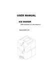
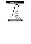
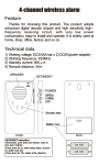
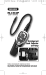
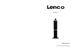
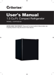
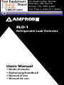
99 Washington Street
Melrose, MA 02176
Phone 781-665-1400
Toll Free 1-800-517-8431
Visit us at www.TestEquipmentDepot.com
RLD-1
Refrigerant Leak Detector
Users Manual
• Mode d’emploi
• Bedienungshandbuch
• Manual d’Uso
• Manual de uso
Refrigerant Leak Detector
Users Manual
July 2009, Rev.1
©2009 Amprobe Test Tools.
All rights reserved. Printed in Taiwan
English
RLD-1
Limited Warranty and Limitation of Liability
Your Amprobe product will be free from defects in material
and workmanship for 1 year from the date of purchase. This
warranty does not cover fuses, disposable batteries or damage
from accident, neglect, misuse, alteration, contamination, or
abnormal conditions of operation or handling. Resellers are not
authorized to extend any other warranty on Amprobe’s behalf.
To obtain service during the warranty period, return the product
with proof of purchase to an authorized Amprobe Test Tools
Service Center or to an Amprobe dealer or distributor. See Repair
Section for details. THIS WARRANTY IS YOUR ONLY REMEDY.
ALL OTHER WARRANTIES - WHETHER EXPRESS, IMPLIED OR
STAUTORY - INCLUDING IMPLIED WARRANTIES OF FITNESS FOR
A PARTICULAR PURPOSE OR MERCHANTABILITY, ARE HEREBY
DISCLAIMED. MANUFACTURER SHALL NOT BE LIABLE FOR ANY
SPECIAL, INDIRECT, INCIDENTAL OR CONSEQUENTIAL DAMAGES
OR LOSSES, ARISING FROM ANY CAUSE OR THEORY. Since some
states or countries do not allow the exclusion or limitation of an
implied warranty or of incidental or consequential damages, this
limitation of liability may not apply to you.
Repair
All test tools returned for warranty or non-warranty repair or
for calibration should be accompanied by the following: your
name, company’s name, address, telephone number, and proof of
purchase. Additionally, please include a brief description of the
problem or the service requested and include the test leads with
the meter. Non-warranty repair or replacement charges should be
remitted in the form of a check, a money order, credit card with
expiration date, or a purchase order made payable to Amprobe®
Test Tools.
In-Warranty Repairs and Replacement – All Countries
Please read the warranty statement and check your battery before
requesting repair. During the warranty period any defective test
tool can be returned to your Amprobe® Test Tools distributor
for an exchange for the same or like product. Additionally ,
in the United States and Canada In-Warranty repair and replacement
units can also be sent to a Amprobe® Test Tools Service
Center (see address below).
Non-Warranty Repairs and Replacement – US and Canada
Non-warranty repairs in the United States and Canada should be
sent to a Amprobe® Test Tools Service Center. Call Amprobe® Test
Tools or inquire at your point of purchase for current repair and
replacement rates.
Non-Warranty Repairs and Replacement – Europe
European non-warranty units can be replaced by your Amprobe®
Test Tools distributor for a nominalv charge.
Test Equipment Depot - 800.517.8431 99 Washington Street Melrose, MA 02176
TestEquipmentDepot.com
RLD-1 Refrigerant Leak Detector
1
2
3
8
4
5
7
6
9
10
11
1 Sensor
2 Sensor Protector
3 LED Leak Indicators
4 Sensitivity Lo Button
5 Power On/Off
6 Reset Button
7 Sensitivity Hi Button
8 Low Battery Indicator
9 Battery Cover
10 Battery Cover Screw
11 DC IN Jack
RLD-1 Refrigerant Leak Detector
CONTENTS
SYMBOLS........................................................................... 2
UNPACKING AND INSPECTION ........................................ 2
INTRODUCTION................................................................. 3
OPERATION........................................................................ 4
LED Leak Indicator Definition ..................................... 4
Automatic Ambient Reset Feature ............................. 5
Feature Sensitivity Adjustment ................................... 6
How To Find Leaks? ..................................................... 7
SPECIFICATION ................................................................. 9
MAINTENANCE AND REPAIR............................................ 10
BATTERY REPLACEMENT . ................................................ 11
New Sensor Replacement............................................. 12
1
SYMBOLS
�
Caution! Refer to the explanation in this Manual
�
Conforms to relevant Australian standards
�
Complies with European Directives
=
Do not dispose of this instrument as unsorted
municipal waste. Contact a qualified recycler for
disposal.
�WARNING!
Do not operate this instrument in the presence
of gasoline, natural gas, propane, or in other
combustible atmospheres.
Unpacking and Inspection
Your shipping carton should include:
2
Alkaline battery (2C Size)
1
User Manual
1
Carry Case
1
AC Adaptor
1
Leak Check Bottle
If any of the items are damaged or missing, return
the complete package to the place of purchase for an
exchange.
Test Equipment Depot - 800.517.8431 99 Washington Street Melrose, MA 02176
TestEquipmentDepot.com
INTRODUCTION
Refrigerant Leakage Detector is the perfect tool for
maintaining the air-condition or a cooling system with
compressor and Refrigerant. This unit uses a newly
developed semi-conductor sensor which is extremely
sensitive to variety of general used Refrigerant
• Microprocessor Control with advanced digital
signal processing.
• Multi color visual display.
• High-median-Low leak sensitivity selector.
• Low battery indication.
• Semiconductor gas sensor.
• Detection of R-134a, R-410A, R-407C, R22 Freon gas.
• Carrying case included.
• 15.5” (40 CM) flexible stainless probe.
• Reference Leak source included.
• Ambient concentration reset.
• Long-life, DC brushless fan.
• Automatic zero and background compensation.
• AC Adapter:@3.3V 0.5A
3
Operation
1. The refrigerant leak detector unit is not equipped
with anti-explosive designs and measures. Do not use
this unit in the environment with the burnable gases.
2. There are some environmental conditions that might
cause error reading:
• Pollutant places.
• Large temperature variation.
• Places with high wind velocity.
• Organic solvent, adhesive vapor, fuel gas and
vesicant will cause abnormal response from the
sensor. Try to avoid the environment involved with
this substance.
• Places fill with too much to Freon Gas.
LED Leak Indicator Definition
Periodically wipe the case with a damp cloth and mild
detergent; do not use abrasives or solvents. If the meter
is not to be used for periods of longer than 60 days,
remove the battery and store separately.
Base
Concentraion
Indiction
More
4
Highest
Concentraion
Indiction
Automatic Ambient Reset Feature
This Refrigerant leak detector features an Automatic
Ambient Reset function that sets the unit to ignore
ambient concentrations of refrigerant.
• Automatic Ambient Setup - Upon initial power
on, the unit automatically sets itself to ignore the
level of refrigerant present at the tip. Only a level,
or concentration, greater than this will cause an
alarm.
�CAUTION!
Be aware that this feature will cause the unit to
ignore any refrigerant present at turn on. In other
words, with the unit off if you place the tip up to
a known leak and switch the unit on, no leak will
be indicated!
• Ambient Reset Feature - Resetting the unit during
operation performs a similar function it programs
the circuit to ignore the level of refrigerant
present at the tip. This allows the user to ‘home-in’
on the source of the leak (higher concentration).
Similarly, the unit can be moved to fresh air and
reset for maximum sensitivity. Resetting the unit
with no refrigerant present (fresh air) causes any
level above zero to be detected.• After the unit
is warmed up, the default sensitivity level is set at
“Medium” and Auto Reset function is “ON”
• Auto Reset function is best used initially when
user is moving around trying to identify leakage
source. Once the leak source is determined, cancel
the Auto Detect function to proceed with leakage
measurement.
• Auto Reset function should be turned OFF when
use in fixed position leakage detection
5
Feature Sensitivity Adjustment
The Instrument provides three levels of sensitivity. When
the unit is switched on, it is set to the Medium sensitivity
level.
• To change the sensitivity, press the “Lo” key.
When the key is pressed, the visual display will
momentarily show the two bottoms LED’s (green)
indicating Low Sensitivity level is selected.
• To switch back to High Sensitivity, press the “Hi”
key. The all LED’s (2 Green+2 Orange+3 Red) will
light momentarily indicating high Sensitivity level
is selected.
Low
Sensitivity level
(Green LED)
Medium
Sensitivity level
(Orange LED)
High
Sensitivity level
(Red LED)
Test Equipment Depot - 800.517.8431 99 Washington Street Melrose, MA 02176
TestEquipmentDepot.com
How To Find Leaks?
NOTE: A sudden whipping of the leak detector probe
or “blowing” into the sensor tip will affect the air flow
over the sensor and cause the instrument to alarm.
(1) Power-Up key
The + key turns the Refrigerant leak detector
instrument ON or OFF function.
Press it once to turn on the Refrigerant leak
detector, the display will illuminate with flash, for 45
seconds to heat up the sensor.
Press and hold this button for 3 second to turn OFF
the power.
(2) Auto Reset & Reset function key
When the Auto Reset function is turned ON, the
meter will monitor background status and fine tune
itself. When Reset LED light is on, it indicates it is
in ON mode. Press “RESET” button and hold for 2
seconds the Reset light will turn off and Auto Reset
function is in OFF mode.
When the Reset light is off, it indicates the Reset
function is in manual mode. Press the “RESET”
button once to enable manual Reset function.
(3) Verify the condition of the unit and sensor
• Set the sensitivity level to “Hi”.
• Open the leak check bottle cover and slowly
move it closer to snake tube nozzle.
• If the indication moves up to high from low then
we should move the check bottle away and the
LED should go off again. This shows that the unit
is under working condition.
• If the unit does not perform as we expect, bring
the unit for maintenance at your local sales
office.
7
(4) Enter the measuring mode
• Place the tip of the leak-detector probe as close
as possible to the site of the suspected leak. Try
to position the probe within 1/4 inch (6 mm) of
the possible leak source.
• Slowly move the probe past each possible
leakage point.
• When the instrument detects a leak source, the
audible tone will alarm. Additionally, the visual
indicators will light from lower to higher; Green
LED then Orange LED then Red LED (highest
concentration) as increasing of level indicate that
the location is close to the source.
When the Instrument signals a leakage, pull the probe
away from the leak for a moment, then bring it back
to pinpoint the location. If the refrigerant leak is large,
setting the sensitivity switch to LOW will make it easier
to find the exact site of the leak.
• Return the sensitivity switch to HIGH before
searching for additional leaks.
• When you’ve finished leak-testing, turn OFF the
instrument and store it in a clean place, protect
the leak detector from possible damage.
8
SPECIFICATION
Detectable Gases : R-134a, R-404A, R-407C, R-410A, R-22
etc
Sensitivity :
H
M
L
R-22,134a
3g/year 15g/year
30g/year
R-404A, 407C, 410A
4g/year 20g/year
40g/year
Alarm Method : Buzzer, Tricolor LED bar Indicator
Power Usage : 2 C size (3V DC) Alkaline Batteries
Snake Tube length : 40cm ( 15.5” )
Dimension / Weight : 222 x 66 x 51 mm ( approximately
418g )
Accessories : Alkaline batteries (C size) X 2 pcs User
manual, leak check bottle, carry case, AC Adapter
Battery Life : Approximately 16 hours normal use.
Auto power OFF: 10 minutes
Disable Auto Power Off : Press and Hold “Hi” button
then power on the meter.
Warm-Up Time : Approximately 45 seconds
Operating Temperature & Humidity : 0 ~40 °C, < 80% RH
Storage Temperature & Humidity : -10 ~60 °C, < 70% RH
Altitude : < 2000M (6500’)
9
� - EMC: Conforms to EN61326-1.This product complies
with requirements of the following European Community
Directives: 89/ 336/ EEC (Electromagnetic Compatibility) and 73/
23/ EEC (Low Voltage) as amended by 93/ 68/ EEC (CE Marking).
However, electrical noise or intense electromagnetic fields in the
vicinity of the equipment may disturb the measurement circuit.
Measuring instruments will also respond to unwanted signals
that may be present within the measurement circuit. Users
should exercise care and take appropriate precautions to avoid
misleading results when making measurements in the presence of
electronic interference.
MAINTENANCE AND REPAIR
If there appears to be a malfunction during the
operation of the meter, the following steps should be
performed in order to isolate the cause of the problem.
1. Check Batteries or replace batteries.
2. Review the operating instructions for possible
mistakes in operating procedure.
Except for the replacement of the battery, repair of the
meter should be performed only by a Factory Authorized
Service Center or by other qualified instrument service
personnel.
The front panel and case can be cleaned with a mild
solution of detergent and water.
Apply sparingly with a soft cloth and allow to dry
completely before using. Do not use aromatic
hydrocarbons, Gasoline or chlorinated solvents for
cleaning.
�WARNING!
The detergent or isopropyl alcohol might damage
the sensor, please keep them from the sensor
through the process.
10
BATTERY REPLACEMENT
• Loose the screw and remove the battery
compartment door located on the bottom of the
instrument as show below (Fig.1).
• Install 2 “C” size alkaline batteries.
• Reinstall the battery cover by aligning it with the
handle.
When the batteries are nearing the end of their useful
life, the Red LED Low Battery indicator illuminates. The
batteries should be replaced as quickly as possible.
Fig. 1
2 “C” size
alkaline batteries
Test Equipment Depot - 800.517.8431 99 Washington Street Melrose, MA 02176
TestEquipmentDepot.com
New Sensor Replacement
The sensor has a limited operative period. Under normal
operation, the sensor should work more than one
year. Expose the sensor under high density of coolant
(>30000ppm) will shorten its life cycle rapidly. It is
important to ensure that sensor surface is free from
water droplets, vapor, oil, grease, dust and any or all
other forms of contaminant. Furthermore, to ensure
good working condition of the unit, sensors must be
replacement periodically when its operative life is over.
�CAUTION!
When replacing new sensor, the worn-out sensor
may be HOT!!
(1) Remove cone cap cover from the tip of snake tube.
(2) Pull out old sensor and insert the new sensor into the
plug (Fig2).
(3) Seal the cap cover over the plug.
Fig. 2
Sensor protector
Sensor
12