1
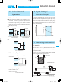
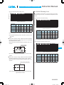
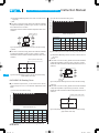
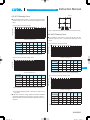
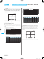
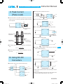
Basic Characteristics Data
Basic Characteristics Data
Model
Circuit method
Switching
frequency
[kHz]
Inrush
current
protection
Input current
[A]
(reference)
Material
Single
sided
Double Series Parallel
sided operation operation
SU/SUC1R5
Flyback converter
350 - 1900 Refer to Table1,2
-
glass fabric base,epoxy resin
Yes
Yes
*1
SU/SUC3
Flyback converter
200 - 1400 Refer to Table1,2
-
glass fabric base,epoxy resin
Yes
Yes
*1
SU/SUC6
Flyback converter
230 - 1950 Refer to Table1,2
-
glass fabric base,epoxy resin
Yes
Yes
*1
SU/SUC10
Flyback converter
250 - 300 Refer to Table1,2
-
glass fabric base,epoxy resin
Yes
Yes
*1
SUT3
Flyback converter
200 - 1400 Refer to Table1,2
-
glass fabric base,epoxy resin
Yes
Yes
*1
SUT6
Flyback converter
230 - 1950 Refer to Table1,2
-
glass fabric base,epoxy resin
Yes
Yes
*1
SUT10
Flyback converter
250 - 300 Refer to Table1,2
-
glass fabric base,epoxy resin
Yes
Yes
*1
*1 Refer to Instruction Manual.
* The value of input current is measured at rated input and load.
Table1 (SUS*** +5V output)
[A]
Input Voltage
Output
Power
5V
12V
24V
48V
1.5W
0.41
0.16
0.08
0.04
3W
0.78
0.32
0.16
0.08
6W
1.32
0.62
0.31
0.15
10W
2.41
0.98
0.49
0.25
Table2 (SUW*** t12V output)
SU.SUC/SUT
Series/Parallel
operation availability
PCB/Pattern
[A]
Input Voltage
Output
Power
5V
12V
24V
48V
1.5W
0.43
0.17
0.09
0.04
3W
0.82
0.33
0.17
0.08
6W
1.54
0.59
0.29
0.15
10W
2.51
1.05
0.52
0.26
SU.SUC/SUT-46
DC-DC Converters PCB Mount type Instruction Manual
1
Pin Terminal Configuration
SU.SUC/SUT-48
10 Using DC-DC Converters
SU.SUC/SUT-59
2
Functions
SU.SUC/SUT-48
11 Options
SU.SUC/SUT-60
SU.SUC/SUT-48
SU.SUC/SUT-48
2.1
Input Voltage Range
2.2
Overcurrent Protection
2.3
Isolation
2.4
Output Voltage Adjustment Range
SU.SUC/SUT-48
SU.SUC/SUT-49
2.5
Remote ON/OFF
SU.SUC/SUT-49
3
Wiring to Input/Output Pin Terminals
SU.SUC/SUT-50
4
Series/Parallel Operation
SU.SUC/SUT-51
4.1
Series Operation
4.2
Redundancy Operation
Input Voltage/Current Range
SU.SUC/SUT-51
6
Assembling and Installation
SU.SUC/SUT-51
Installation
6.2
Automatic Mounting
6.3
Hand Mounting
6.4
Soldering Conditions
6.5
Stress to Pin Terminals
6.6
Cleaning
SU.SUC/SUT-61
SU.SUC/SUT
SU.SUC/SUT-52
SU.SUC/SUT-52
SU.SUC/SUT-52
SU.SUC/SUT-53
Safety Standards
SU.SUC/SUT-53
8
Derating
SU.SUC/SUT-54
SU.SUC/SUT-54
SU.SUC/SUT-54
8.1
SU/SUC1R5 Derating Curve
8.2
SU/SUC3 Derating Curve
8.3
SU/SUC6 Derating Curve
8.4
SU/SUC10 Derating Curve
8.5
SUT3 Derating Curve
8.6
SUT6 Derating Curve
SU.SUC/SUT-57
SU.SUC/SUT-57
8.7
SUT10 Derating Curve
SU.SUC/SUT-58
Peak Current (Pulse Load)
12 Delivery Package Information
SU.SUC/SUT-51
SU.SUC/SUT-52
7
9
SU.SUC/SUT-60
Outline of Options
SU.SUC/SUT-51
SU.SUC/SUT-51
5
6.1
11.1
SU.SUC/SUT-55
SU.SUC/SUT-56
SU.SUC/SUT-59
SU.SUC/SUT-47
DC-DC Converters PCB Mount type
1 Pin Terminal Configuration
Instruction Manual
¿Case Connecting Pin Terminal
Units come with a case connecting pin terminal. If this pin terminal is connected to -Vin, radiation noise from the main body
decreases. Solder the case connecting pin terminal to PCB to
Table 1.1 Pin Terminal Configuration and Functions
Pin Terminal
Pin No.
Function
Name
+Vin
+DC Input
1
RC
Remote ON/OFF (excluding 1R5)
2
-Vin
-DC Input
3
+Vout
+DC Output
4
COM
GND of Output Voltage (for Dual Output)
5
Output Voltage Adjustment (please see 2.4)
TRM
6
-Vout
-DC Output
7
If connected to -Vin, a case potential becomes
Case Connecting
fixed and radiation noise decreases (applicable
8
Pin
only to SUC series).
improve reliability.
2 Functions
2.1 Input Voltage Range
¡If output voltage value doesn’t fall within specifications, a unit may
not operate in accordance with specifications and/or fail.
2.2 Overcurrent Protection
¿Single Output
¡Overcurrent Operation
An overcurrent protection circuit is built-in and activated at 105%
View from Above
1
2
Input
3
+Vin
+Vout
RC
TRM
-Vin
-Vout
8
4
of the rated current or above. It prevents the unit from short circuit
6
and overcurrent for less than 20 seconds. The unit automatically
Load
recovers when the fault condition is removed.
¡Current Foldback Characteristic
If a model that has a current foldback characteristic is connected
7
Case Connecting Pin
to a non-linear load such as lamp or motor, or to a constant current load, it may not start up. Please see the characteristics be-
¿Dual(t)Output
low.
1
+Vout
+Vin
SU.SUC/SUT
COM
Input
2
4
5
Load
Load
RC
TRM
3
6
Load
-Vin
-Vout
7
Case
Connecting
Pin
8
Output Voltage [V]
View from Above
V
A
100
Load Factor [%]
Fig.1.1 Pin Configuration
: Load Characteristic of Power Supply
Table 1.2 Pin Terminal Configuration and Functions
Pin Terminal
Pin No.
Function
Name
-Vin
-DC Input
1
RC
Remote ON/OFF
2
+Vin
+DC Input
3
+Vout
+DC Output
4
NC (Single output)
5
COM (Dual output) GND of Output Voltage
TRM
Output Voltage Adjustment
6
-Vout
-DC Output
7
Case Connecting If connected to -Vin, a case potential becomes
8
Pin
fixed and radiation noise decreases.
8
1
2
3
4
5
6
7
8
8
Fig.1.2 Pin Terminal Configuration
SU.SUC/SUT-48
Fig.2.1 Current Foldback Characteristic
2.3 Isolation
¡When you run a Hi-Pot test as receiving inspection, gradually increase the voltage to start. When you shut down, decrease the
voltage gradually by using a dial. Please avoid a Hi-Pot tester
with a timer because, when the timer is turned ON or OFF, it may
generate a voltage a few times higher than the applied voltage.
8
Bottom View
: Characteristic of Load (Lamp, Motor or Constant
Current Load, etc.)
Note : The output may be locked out at Point A when the unit is
connected to a lamp, motor or constant current load.
Instruction Manual
DC-DC Converters PCB Mount type
2.4 Output Voltage Adjustment Range
+Vin
¡The output voltage is adjustable through an external potentiometer. Adjust only within the range of t5% of the rated voltage.
RC
External
Circuit
2.2K
¡To increase the output voltage, turn the potentiometer clockwise
and connect in such a way that the resistance value between 2
Control
Circuit
47K
-Vin
and 3 becomes small.
Fig.2.3 Internal Circuits of Remote ON/OFF
To decrease the output voltage, turn the potentiometer counter-
+Vin
clockwise.
¡Please use a wire as short as possible to connect to the potentiometer and connect it from the pin terminal on the power supply
side. Temperature coefficient deteriorates when some types of
+Vin
+Vin
RC
RC
RC
resistors and potentiometers are used. Please use the following
types.
Resistor..............Metal Film Type, Temperature Coefficient of t100ppm/C or below
Potentiometer...Cermet Type, Temperature Coefficient of t300ppm/C or below
¡If output voltage adjustment is not required, open the pin terminal
TRM.
¡In the case of dual output, tvoltages are adjusted simultaneously.
+Vout
Output
External Resistor
R1
1
TRM
-Vout
3
External VR Load
2
External Resistor
R2
-Vin
-Vin
Input 5V
-Vin
Input 12V
Input 24, 48V
Fig.2.4 Examples of Using an External Remote ON/OFF Circuit
Table 2.2 Specification of Remote ON/OFF
Voltage Level of the pin terminal RC (VRC) SU/SUC3/SUT3, SU/SUC6/SUT6 Output
Open or Short or 0V[VRC[0.3V
ON
2.0V[VRC[9.0V
OFF
¡Please keep the voltage level of the pin terminal RC (VRC) at 9.0V
or below.
¡If you do not use the Remote ON/OFF function, please short out
between the pin terminals RC and -Vin to prevent malfunction.
(2) SU/SUC10/SUT10
Fig.2.2 Connecting External Devices
Table 2.1 List of External Devices
Constant of External Device [W]
Item # Output Voltage
1
2
3
4
5
6
3.3V
5V
12V
15V
t12V
t15V
VR
1K
1K
5K
5K
5K
5K
(Adjustable within t5%)
R1
R2
100
100
100
270
10K
1.2K
10K
470
18K
470
18K
470
¡The output of the power supply turns ON when the pin terminal
RC is connected to the pin terminal -Vin. When the pin terminal
RC is open or the voltage of the pin terminal RC is between 2.4 to
7.0 V, the output of the power supply goes OFF.
¡When the voltage of the pin terminal RC is between 1.2 to 2.4V,
an output voltage value may be an uncertain value which is less
than the rated voltage.
¡Please see the following diagram for how to use the pin terminal
RC.
Vcc
RC
2.5 Remote ON/OFF (Excluding 1R5)
¡You can turn the power supply ON or OFF without turning the input power ON or OFF through the pin terminal RC.
-Vin
or
Transistor
or
Relay
IC
Fig.2.5 Examples of Using an External Remote ON/OFF Circuit
(1) SU/SUC3/SUT3 and SU/SUC6/SUT6
¡The output of the power supply turns ON when the pin terminal
RC is connected to the pin terminal -Vin. When the voltage of the
pin terminal RC is between 2.0 to 9.0V, the output of the power
supply goes OFF.
¡When the voltage of the pin terminal RC is between 0.3 to 2.0V,
the output voltage value may be an uncertain value which is less
than the rated voltage.
¡Please see the following diagram for how to use the pin terminal
RC.
Table 2.3 Specification of Remote ON/OFF
Voltage Level of the pin terminal RC (VRC) SU/SUC10/SUT10 Output
Short or 0V[VRC[1.2V
ON
Open or 2.4V[VRC[7.0V
OFF
¡When the pin terminal RC is at the ”Low” level, outflowing current
is 0.5mA typ. When Vcc is used, please make sure that the voltage of Vcc is 7.0V or less.
¡If you do not use the Remote ON/OFF function, please short out
between the pin terminals RC and -Vin.
SU.SUC/SUT-49
SU.SUC/SUT
Instruction Manual
DC-DC Converters PCB Mount type
3 Wiring to Input/Output
Pin Terminals
(b)
Fuse
Input
+Vin
Schottky Barrier
Diode
-Vin
¡Basically, SU/SUC/SUT series do not need any external capacitor. However, you can create a P-shaped filter circuit by adding a
capacitor Ci near the input pin terminal and reduce reflected input
noise from a converter. Please connect the capacitor as needed.
¡When you use a capacitor Ci, please use the one with high frequency and good temperature characteristics.
¡If the power module is to be turned ON/OFF directly with a switch,
inductance from the input line will induce a surge voltage several
Fig.3.2 Connecting a Reverse Voltage Protection Circuit
¡Basically, SU/SUC/SUT series do not need any external capacitor. However, if you want to further reduce the output ripple noise,
connect an electrolytic capacitor or a ceramic capacitor Co to the
output pin terminal as shown below.
+Vout
+Vout
times that of the input voltage and it may damage the power modCo
ule. Make sure that the surge is absorbed, for example, by connecting an electrolytic capacitor between the input pins.
Load
-Vout
¡If an external filter containing L (inductance) is added to the input
line or a wire from the input source to the DC-DC converter is
long, not only the reflected input noise becomes large, but also
Co
Load
Co
Load
COM
-Vout
SUS/SUCS
SUW/SUCW
Fig.3.3 Connecting Example of an External Capacitor to the Output Side
the output of the converter may become unstable. In such case,
Table 3.2 Recommended Capacitance of External Capacitor on the Output Side [ F]
connecting Ci to the input pin terminal is recommended.
¡If you use an aluminum electrolytic capacitor, please pay attention
to its ripple current rating.
L
Input
+Vin
SU/SUC1R5 SU/SUC3/SUT3 SU/SUC6/SUT6 SU/SUC10/SUT10
1 - 100
1 - 100
1 - 100
1 - 100
1 - 220
1 - 220
1 - 100
1 - 100
1 - 220
1 - 220
1 - 100
1 - 100
1 - 220
1 - 220
1 - 100
1 - 100
Ci
*If you use a ceramic capacitor, keep the capacitance within the
rage between about 0.1 to 10 F.
-Vin
SU.SUC/SUT
Model
Output Voltage(V)
3.3
5
12
15
Fig.3.1 Connecting an External Capacitor to the Input Side
Table 3.1 Recommended Capacitance of an External Capacitor on the Input Side [ F]
Model
Input Voltage(V)
5
12
24
48
SU/SUC1R5 SU/SUC3/SUT3 SU/SUC6/SUT6 SU/SUC10/SUT10
10 - 100
10 - 47
10 - 33
4.7 - 10
10 - 220
10 - 100
10 - 47
10 - 22
10 - 470
10 - 220
10 - 100
10 - 47
10 - 470
10 - 220
10 - 100
10 - 47
*Please adjust the capacitance in accordance with a degree of the
effect you want to achieve.
¡If a reverse polarity voltage is applied to the input pin terminal, the
power supply will fail.
If there is a possibility that a reverse polarity voltage is applied,
connect a protection circuit externally as described below.
(a)
Schottky Barrier Diode
+Vin
Input
-Vin
Schottky barrier diode generates a power loss
of input current multiplied by forward voltage.
SU.SUC/SUT-50
*Please adjust the capacitance in light of the effect you want to
achieve.
*If you need to use an external capacitor whose capacitance exceeds the range provided in Table 3.2, please contact us.
¡If the distance between the output and the load is long and therefore the noise is created on the load side, connect a capacitor
externally to the load as shown below.
+Vin
+Vout
-Vin
-Vout
Load
Input
Instruction Manual
DC-DC Converters PCB Mount type
4 Series/Parallel
Operation
5 Input Voltage/
Current Range
¡If you use a non-regulated power source for input, please check
and make sure that its voltage fluctuation range and ripple voltage
4.1 Series Operation
¡You can use the power supplies in series operation by wiring as
shown below. In the case of (a) below, the output current should
be lower than the rated current of a power supply with the lowest
rated current among power supplies that are serially connected.
do not exceed the input voltage range shown in specifications.
¡Please select an input power source with enough capacity, taking
into consideration of the start-up current (Ip), which flows when a
DC-DC converter starts up.
Please make sure that no current exceeding the rated current
Input Voltage Range
flows into a power supply.
(a)
Power
Supply
+
-
-
D1
D2
D3
D4
Power
Supply
Power
Supply
D1 - D4 : Use a schottky barrier diode
+
D1
-
Load
+
12V or more
Load
Power
Supply
+
Ip
Input Current [A]
5V or less
D2
-
Input Voltage [V]
D1, D2 : Use a schottky barrier diode
with low forward voltage.
with low forward voltage.
Fig.5.1 Input Current Characteristics
(b)
+
6 Assembling and Installation
Load
-
+
Power
Supply -
¡You can install the units in any direction. Place them in such a
way that there is enough ventilation so that heat does not get accumulated around them.
Fig.4.1 Series Operation
¡Do not place a rand or a pattern layout in the hatched area shown
in Fig. 6.1, 6.2. Doing so may cause insulation failure on the PCB
4.2 Redundancy Operation
surface on which the power supply is mounted.
A
¡You can use the power supplies in redundancy operation by wiring
as shown below.
+
I1
Power
Supply
A
Outer Contour
of the Unit
I3
+Vin
+Vout
-Vin
-Vout
Load
Power
Supply
SU.SUC/SUT
6.1 Installation
Load
Power
Supply
+
A: SU Series
2mm
SUC Series 2.5mm
I2
Fig.6.1 Area where Pattern Layout should not be Placed for SU/SUC
-
Outline
4.4
¡Even a slight difference in output voltage can affect the balance
between the values of I1 and I2.
1.75
2.3
Fig.4.2 Redundancy Operation
Please make sure that the value of I3 does not exceed the rated
I3 [ Rated Current Value
2.3
current of a power supply.
5.2
Case Connecting Pin
Fig.6.2 Area where Pattern Layout should not be Placed for SUT
SU.SUC/SUT-51
Instruction Manual
DC-DC Converters PCB Mount type
6.2 Automatic Mounting (TYPE: BP)
(C)
¡To mount SU series automatically, use the transformer area near
the center of the PCB as a pickup point. To mount SUC series au-
Tx
tomatically, use the central area of the case as a pickup point. If
Ty2
the bottom dead point of a suction nozzle is too low when mount-
Ty1
Tp
ing, excessive force is applied to the transformer, which could
cause damage. Please mount carefully.
Please see the External View for details of the pickup point.
A
A’
B
B’
C
time(s)
6.3 Hand Mounting (TYPE:B,C SUT)
A
¡To mount SU series manually, it must be push the transformer
placed center of PS.
A’
¡To mount SUC series manually, it must be push the center of
case.
B
¡Due to prevent failure, PS should not be pull after soldering with
PCB.
push
push
1.0 - 5.0C/s
Ty1 : 160t20C
Ty2 : 180t20C
Ty1 - Ty2 : 120s max
1.0 - 5.0C/s
Tp : Max 245C 10s max
Tx : 220C or more : 70s max
1.0 - 5.0C/s
B’
C
Fig.6.5 Recommend Reflow Soldering Conditions
: 260C
15 seconds or less
(3) Soldering Iron
: maximum 360C
5 seconds or less
6.5 Stress to Pin Terminals
Fig.6.3 Hand mounting
¡If too much stress is applied to input/output pin terminals of the
power supply, internal connection may come down. If you apply
6.4 Soldering Conditions
stress as shown below, please kept it at 19.6N (2kgf) or less verti-
(1) Reflow Soldering (except SUT, SUCOOC-C)
SU.SUC/SUT
(2) Flow Soldering
¡Fig.6.4 shows conditions for the reflow soldering for SU/SUC
series. Please make sure that the temperatures of pin terminals
+Vin and -Vout shown in Fig.6.4 do not exceed the temperatures
shown in Fig.6.5.
¡If time or temperature of the reflow soldering goes beyond the
conditions, reliability of internal components may be compromised.
Please use the unit under the recommended reflow conditions.
cally.
¡Input/output pin terminals are soldered to the PCB internally. Do
not pull or bend a lead powerfully.
¡If it is expected that stress is applied to the input/output pin terminals due to vibration or impact, reduce the stress to the pin
terminals by taking such measures as fixing the unit to the PCB by
silicone rubber, etc.
¡With this reflow profile, internal solder melts down. When transporting the unit within the reflow oven, please do not give vibration
to the unit.
¡Please avoid reflow soldering after applying adhesive or coating to
the unit.
¡You can reflow solder up to 2 times. Do not reflow solder when
the power supply is mounted on the back surface of the PCB be-
19.6N(2kgf)
or less
19.6N(2kgf)
or less
19.6N(2kgf)
or less
19.6N(2kgf)
or less
Fig.6.6 Strength of Input/Output Pin Terminals for SU/SUC
cause the unit may drop.
+Vin
-Vout
A part
Fig.6.4 Temperature Measuring Points when Setting Reflow Soldering Conditions
(View from Above)
Less than
A
19.6N(2kgf)
Fig.6.7 Strength of Input/Output Pin Terminals for SUT
SU.SUC/SUT-52
DC-DC Converters PCB Mount type
Instruction Manual
¿SU/SUC6
6.6 Cleaning (except SUCOOC-C)
¡If you need to clean the unit, please clean it under the following
conditions.
Cleaning Method: Varnishing, Ultrasonic or Vapor Cleaning
Cleaning agent: IPA (Solvent type)
SUS6053R3
SUS60505
SUS60512
SUS60515
SUW60512
SUW60515
SUS6123R3
SUS61205
SUS61212
SUS61215
SUW61212
SUW61215
SUS6243R3
SUS62405
SUS62412
SUS62415
SUW62412
SUW62415
SUS6483R3
SUS64805
SUS64812
SUS64815
SUW64812
SUW64815
SUCS6053R3
SUCS60505
SUCS60512
SUCS60515
SUCW60512
SUCW60515
SUCS6123R3
SUCS61205
SUCS61212
SUCS61215
SUCW61212
SUCW61215
SUCS6243R3
SUCS62405
SUCS62412
SUCS62415
SUCW62412
SUCW62415
SUCS6483R3
SUCS64805
SUCS64812
SUCS64815
SUCW64812
SUCW64815
SUS10053R3
SUS100505
SUS100512
SUS100515
SUW100512
SUW100515
SUS10123R3
SUS101205
SUS101212
SUS101215
SUW101212
SUW101215
SUS10243R3
SUS102405
SUS102412
SUS102415
SUW102412
SUW102415
SUS10483R3
SUS104805
SUS104812
SUS104815
SUW104812
SUW104815
SUCS10053R3
SUCS100505
SUCS100512
SUCS100515
SUCW100512
SUCW100515
SUCS10123R3
SUCS101205
SUCS101212
SUCS101215
SUCW101212
SUCW101215
SUCS10243R3
SUCS102405
SUCS102412
SUCS102415
SUCW102412
SUCW102415
SUCS10483R3
SUCS104805
SUCS104812
SUCS104815
SUCW104812
SUCW104815
SUTS3123R3
SUTS31205
SUTS31212
SUTS31215
SUTW31212
SUTW31215
SUTS3243R3
SUTS32405
SUTS32412
SUTS32415
SUTW32412
SUTW32415
SUTS3483R3
SUTS34805
SUTS34812
SUTS34815
SUTW34812
SUTW34815
SUTS6123R3
SUTS61205
SUTS61212
SUTS61215
SUTW61212
SUTW61215
SUTS6243R3
SUTS62405
SUTS62412
SUTS62415
SUTW62412
SUTW62415
SUTS6483R3
SUTS64805
SUTS64812
SUTS64815
SUTW64812
SUTW64815
SUTS10123R3
SUTS101205
SUTS101212
SUTS101215
SUTW101212
SUTW101215
SUTS10243R3
SUTS102405
SUTS102412
SUTS102415
SUTW102412
SUTW102415
SUTS10483R3
SUTS104805
SUTS104812
SUTS104815
SUTW104812
SUTW104815
Cleaning Time: Within total 2 minutes for varnishing, ultrasonic
and vapor cleaning
¡Please dry the unit sufficiently after cleaning.
¡If you do ultrasonic cleaning, please keep the ultrasonic output at
15W/ or below.
7 Safety Standards
¡To apply for a safety standard approval using the power supply,
please meet the following conditions. Please contact us for details.
¿Please use the unit as a component of an end device.
¿The area between the input and the output of the unit is isolated
functionally. Depending upon the input voltage, basic insulation,
dual insulation or enhanced insulation may be needed. In such
case, please take care of it within the structure of your end-device.
Please contact us for details.
¡Please use the following model names when you apply for a safety standard approval.
¿SU/SUC1R5
SUS1R5053R3
SUS1R50505
SUS1R50512
SUS1R50515
SUW1R50512
SUW1R50515
SUS1R5123R3
SUS1R51205
SUS1R51212
SUS1R51215
SUW1R51212
SUW1R51215
SUS1R5243R3
SUS1R52405
SUS1R52412
SUS1R52415
SUW1R52412
SUW1R52415
SUS1R5483R3
SUS1R54805
SUS1R54812
SUS1R54815
SUW1R54812
SUW1R54815
SUCS1R5053R3
SUCS1R50505
SUCS1R50512
SUCS1R50515
SUCW1R50512
SUCW1R50515
SUCS1R5123R3
SUCS1R51205
SUCS1R51212
SUCS1R51215
SUCW1R51212
SUCW1R51215
SUCS1R5243R3
SUCS1R52405
SUCS1R52412
SUCS1R52415
SUCW1R52412
SUCW1R52415
SUCS1R5483R3
SUCS1R54805
SUCS1R54812
SUCS1R54815
SUCW1R54812
SUCW1R54815
¿SU/SUC3
SUS3053R3
SUS30505
SUS30512
SUS30515
SUW30512
SUW30515
SUS3123R3
SUS31205
SUS31212
SUS31215
SUW31212
SUW31215
SUS3243R3
SUS32405
SUS32412
SUS32415
SUW32412
SUW32415
SUS3483R3
SUS34805
SUS34812
SUS34815
SUW34812
SUW34815
SUCS3053R3
SUCS30505
SUCS30512
SUCS30515
SUCW30512
SUCW30515
SUCS3123R3
SUCS31205
SUCS31212
SUCS31215
SUCW31212
SUCW31215
SUCS3243R3
SUCS32405
SUCS32412
SUCS32415
SUCW32412
SUCW32415
SUCS3483R3
SUCS34805
SUCS34812
SUCS34815
SUCW34812
SUCW34815
¿SU/SUC10
¿SUT3
SUTS3053R3
SUTS30505
SUTS30512
SUTS30515
SUTW30512
SUTW30515
¿SUT6
SUTS6053R3
SUTS60505
SUTS60512
SUTS60515
SUTW60512
SUTW60515
¿SUT10
SUTS10053R3
SUTS100505
SUTS100512
SUTS100515
SUTW100512
SUTW100515
SU.SUC/SUT-53
SU.SUC/SUT
DC-DC Converters PCB Mount type
Instruction Manual
(3) Temperature Measuring Points in the case of Forced Air Cool-
8 Derating
ing (1m/s)
1 SU1R5
¡In the case of forced air cooling, please have sufficient ventilation
to keep the temperature of point A in Fig.8.3 at 105C or below.
8.1 SU/SUC1R5 Derating Curve
¡If you derate the output current, you can use the unit in the temperature range from -40C to the maximum temperature shown
Please also make sure that the ambient temperature does not exceed 85C.
Point A
below.
(1) In the case of Convection Cooling
Load Factor [%]
100
A
B
50
Fig.8.3 Temperature Measuring Point in the case of Forced Air Cooling
0
-40
-20
0
20
40
(55) 60
80 (85)
100
Ambient Temperature [C]
Output Voltage(V)
3.3
5
12
15
t12
t15
5
A
A
A
A
A
A
12
A
A
A
A
A
A
Input Voltage(V)
24
A
A
A
A
A
A
48
B
B
B
B
B
B
2 SUC1R5
¡In the case of forced air cooling, please have sufficient ventilation
to keep the temperature of point B in Fig.8.4 at 95C or below.
Please also make sure that the ambient temperature does not exceed 85C.
Point B (Center of the Case)
Fig.8.1 Derating Curve for Convection Cooling (SU/SUC1R5)
(2) In the case of Forced Air Cooling (1m/s)
A
Fig.8.4 Temperature Measuring Point in the case of Forced Air Cooling
(Upper Surface of the Case)
50
8.2 SU/SUC3 Derating Curve
0
-40
-20
0
20
40
60
80 (85)
100
Ambient Temperature [C]
Output Voltage(V)
below.
3.3
5
12
15
t12
t15
5
A
A
A
A
A
A
12
A
A
A
A
A
A
24
A
A
A
A
A
A
48
A
A
A
A
A
A
Input Voltage(V)
¡If you derate the output current, you can use the unit in the temperature range from -40C to the maximum temperature shown
(1) In the case of Convection Cooling
Fig.8.2 Derating Curve for Forced Air Cooling (1m/s) (SU/SUC1R5)
100
Load Factor [%]
SU.SUC/SUT
Load Factor [%]
100
A
B
50
C
0
-40
-20
0
20
40
(55) 60
(71)
80 (85)
100
Ambient Temperature [C]
Output Voltage(V)
Input Voltage(V)
3.3
5
12
15
t12
t15
5
A
A
B
B
A
B
12
A
A
B
B
A
B
24
A
A
B
B
A
B
48
B
B
B
B
A
C
Fig.8.5 Derating Curve for Convection Cooling (SU/SUC3)
SU.SUC/SUT-54
DC-DC Converters PCB Mount type
(2) In the case of Forced Air Cooling (1m/s)
8.3 SU/SUC6 Derating Curve
100
Load Factor [%]
Instruction Manual
B
¡If you derate the output current, you can use the unit in the temperature range from -40C to the maximum temperature shown
A
below.
50
(1) In the case of Convection Cooling
-20
0
20
40
60
80 (85)
100
Ambient Temperature [C]
Output Voltage(V)
3.3
5
12
15
t12
t15
5
A
B
B
B
B
B
12
A
A
A
A
A
B
Input Voltage(V)
24
A
A
B
A
A
B
48
A
A
A
A
A
B
Load Factor [%]
100
0
-40
A
50
B
0
-40
-20
Output Voltage(V)
Fig.8.6 Derating Curve for Forced Air Cooling (1m/s) (SU/SUC3)
(3) Temperature Measuring Points in the case of Forced Air Cooling (1m/s)
1 SU3
¡In the case of forced air cooling, please have sufficient ventilation
to keep the temperature of point A in Fig.8.7 at 115C or below and
Please also make sure that the ambient temperature does not ex-
20
40
(55) 60
(71)
80 (85)
100
Ambient Temperature [C]
3.3
5
12
15
t12
t15
5
B
B
B
B
B
B
12
B
B
B
B
B
B
24
B
B
B
B
B
B
48
B
B
A
A
A
A
Input Voltage(V)
that of Point B at 120C or below.
0
Fig.8.9 Derating Curve for Convection Cooling (SU/SUC6)
(2) In the case of Forced Air Cooling (1m/s)
ceed 85C.
Point A Point B
Load Factor [%]
100
A
B
50
SU.SUC/SUT
0
-40
-20
0
20
40
60
(75) 80 (85)
100
Ambient Temperature [C]
Fig.8.7 Temperature Measuring Points in the case of Forced Air Cooling
2 SUC3
¡In the case of forced air cooling, please have sufficient ventilation
Output Voltage(V)
Input Voltage(V)
3.3
5
12
15
t12
t15
5
B
B
A
A
A
A
to keep the temperature of point C in Fig.8.8 at 100C or below.
12
B
B
A
A
A
A
Please also make sure that the ambient temperature does not ex-
24
B
B
A
A
A
A
ceed 85C.
48
B
B
A
A
A
A
Point C (Center of the Case)
Fig.8.10 Derating Curve for Forced Air Cooling (1m/s) (SU/SUC6)
Fig.8.8 Temperature Measuring Point in the case of Forced Air Cooling
(Upper Surface of the Case)
SU.SUC/SUT-55
Instruction Manual
DC-DC Converters PCB Mount type
(3) Temperature Measuring Points in the case of Forced Air Cool-
(2) In the case of Forced Air Cooling (1m/s)
ing (1m/s)
that of Point B at 115C or below.
Please also make sure that the ambient temperature does not exceed 85C.
100
Load Factor [%]
1 SU6
¡In the case of forced air cooling, please have sufficient ventilation
to keep the temperature of point A in Fig.8.11 at 95C or below and
A
B
50
0
-40
-20
0
Point B Point A
20
40
60
(71)
80 (85)
100
Ambient Temperature [C]
Output Voltage(V)
3.3
5
12
15
t12
t15
5
B
B
B
B
A
A
12
B
B
B
B
A
A
24
B
B
B
B
A
A
48
B
B
B
B
B
B
Input Voltage(V)
Fig.8.11 Temperature Measuring Points in the case of Forced Air Cooling
2 SUC6
¡In the case of forced air cooling, please have sufficient ventilation
Fig.8.14 Derating Curve for Forced Air Cooling (1m/s) (SU/SUC10)
to keep the temperature of point C in Fig.8.12 at 95C or below.
Please also make sure that the ambient temperature does not ex-
(3) Temperature Measuring Points in the case of Forced Air Cooling (1m/s)
ceed 85C.
1 SU10
¡In the case of forced air cooling, please have sufficient ventilation
to keep the temperature of point A in Fig.8.15 at 105C or below.
Point C (Center of the Case)
Please also make sure that the ambient temperature does not exceed 85C.
Fig.8.12 Temperature Measuring Point in the case of Forced Air Cooling
(Upper Surface of the Case)
Point A
8.4 SU/SUC10 Derating Curve
Fig.8.15 Temperature Measuring Point in the case of Forced Air Cooling
¡If you derate the output current, you can use the unit in the temperature range from -40C to the maximum temperature shown
below.
2 SUC10
¡In the case of forced air cooling, please have sufficient ventilation
to keep the temperature of point B in Fig.8.16 at 95C or below.
Please also make sure that the ambient temperature does not ex-
(1) In the case of Convection Cooling
ceed 85C.
100
Load Factor [%]
SU.SUC/SUT
Point B (Center of the Case)
A
50
B
0
-40
-20
0
20
40
(55) 60
(71)
80 (85)
100
Ambient Temperature [C]
Output Voltage(V)
3.3
5
12
15
t12
t15
5
B
A
A
A
A
A
12
B
A
A
A
A
A
24
B
A
A
A
A
A
48
B
B
B
B
B
B
Input Voltage(V)
Fig.8.13 Derating Curve for Convection Cooling (SU/SUC10)
SU.SUC/SUT-56
Fig.8.16 Temperature Measuring Point in the case of Forced Air Cooling
(Upper Surface of the Case)
DC-DC Converters PCB Mount type
Instruction Manual
Point A
8.5 SUT3 Derating Curve
¡If you derate the output current, you can use the unit in the temperature range from -40C to the maximum temperature shown
below.
(1) In the case of Convection Cooling
Load Factor [%]
100
A
Fig.8.19 Temperature Measuring Point in the case of Forced Air Cooling
B
50
C
0
-40
-20
0
20
40
(55) 60
8.6 SUT6 Derating Curve
(71)
80 (85)
100
Ambient Temperature [C]
¡If you derate the output current, you can use the unit in the temperature range from -40C to the maximum temperature shown
below.
Output Voltage(V)
3.3
5
12
15
t12
t15
5
A
A
B
B
A
B
12
A
A
B
B
A
B
24
A
A
B
B
A
B
48
B
B
B
B
A
C
(1) In the case of Convection Cooling
100
Load Factor [%]
Input Voltage(V)
A
B
50
Fig.8.17 Derating Curve for Convection Cooling (SUT3)
0
-40
-20
0
(2) In the case of Forced Air Cooling (1m/s)
Output Voltage(V)
Load Factor [%]
100
B
-20
0
20
40
60
80 (85)
100
Ambient Temperature [C]
3.3
5
12
15
t12
t15
5
A
B
B
B
B
B
12
A
A
A
A
A
B
Input Voltage(V)
(55) 60
(71)
80
100
5
12
15
t12
t15
5
B
B
B
B
B
B
12
B
B
B
B
B
B
24
B
B
B
B
B
B
48
B
B
A
A
A
A
SU.SUC/SUT
Fig.8.20 Derating Curve for Convection Cooling (SUT6)
24
A
A
B
A
A
B
48
A
A
A
A
A
B
Fig.8.18 Derating Curve for Forced Air Cooling (1m/s) (SUT3)
(2) In the case of Forced Air Cooling (1m/s)
100
Load Factor [%]
Output Voltage(V)
40
3.3
Input Voltage(V)
A
50
0
-40
20
Ambient Temperature [C]
A
B
50
0
-40
-20
0
20
40
60
(71)
80 (85)
100
Ambient Temperature [C]
(3) Temperature Measuring Points in the case of Forced Air Cooling (1m/s)
¡In the case of forced air cooling, please have sufficient ventilation
to keep the temperature of point A in Fig.8.19 at 100C or below.
Output Voltage(V)
Input Voltage(V)
3.3
5
12
15
t12
t15
5
B
B
B
B
B
B
Please also make sure that the ambient temperature does not ex-
12
B
B
A
A
A
A
ceed 85C.
24
B
B
A
A
A
A
48
B
B
A
A
A
A
Fig.8.21 Derating Curve for Forced Air Cooling (1m/s) (SUT6)
SU.SUC/SUT-57
DC-DC Converters PCB Mount type
ing (1m/s)
¡In the case of forced air cooling, please have sufficient ventilation
to keep the temperature of point A in Fig.8.22 at 95C or below.
Please also make sure that the ambient temperature does not exceed 85C.
Point A
(2) In the case of Forced Air Cooling (1m/s)
100
Load Factor [%]
(3) Temperature Measuring Points in the case of Forced Air Cool-
Instruction Manual
A
50
0
-40
-20
0
20
40
60
(71)
80 (85)
100
Ambient Temperature [C]
Output Voltage(V)
3.3
5
12
15
t12
t15
5
A
A
A
A
A
A
12
A
A
A
A
A
A
24
A
A
A
A
A
A
48
A
A
A
A
A
A
Input Voltage(V)
Fig.8.22 Temperature Measuring Point in the case of Forced Air Cooling
Fig.8.24 Derating Curve for Forced Air Cooling (1m/s) (SUT10)
8.7 SUT10 Derating Curve
¡If you derate the output current, you can use the unit in the temperature range from -40C to the maximum temperature shown
below.
(1) In the case of Convection Cooling
Load Factor [%]
ing (1m/s)
¡In the case of forced air cooling, please have sufficient ventilation
to keep the temperature of point A in Fig.8.25 at 95C or below.
Please also make sure that the ambient temperature does not ex-
100
SU.SUC/SUT
(3) Temperature Measuring Points in the case of Forced Air Cool-
ceed 85C.
B
A
C
Point A
50
0
-40
-20
0
20
40
50 (55) 60
(71)
80
100
Ambient Temperature [C]
Output Voltage(V)
3.3
5
12
15
t12
t15
5
C
C
A
A
C
C
12
B
A
A
A
B
A
24
C
C
C
C
C
B
48
C
C
C
C
C
C
Input Voltage(V)
Fig.8.23 Derating Curve for Convection Cooling (SUT10)
SU.SUC/SUT-58
Fig.8.25 Temperature Measuring Point in the case of Forced Air Cooling
DC-DC Converters PCB Mount type
Instruction Manual
¡When Using a Non-regulated Power Source
9 Peak Current
(Pulse Load)
+Vin
¡If a load connected to a converter is a pulse load, you can provide
a pulse current by connecting an electrolytic capacitor externally
to the output side.
+Vin
+Vout
+Vout
COM
C
-Vin
Pulse Load
Vo
-Vin
-Vout
-Vout
-15V
¡When Using a Battery-operated Device
Iop
COM
0
COM
-Vin
+Vin
+15V
+Vout
-Vout
+15V
0
-15V
¡When a Floating Mechanism is Required for the Output Circuit
External Electrolytic
Capacitor
+Vin
+Vout
Iop
Load
Iop:Current at Peak
Is :Steady-state Current
Waveform of Pulse
Load Current
-Vin
-Vout
Is
0
Floating from
the GND level
¡To Draw a Reverse Polarity Output
DVo
Waveform of
Output Voltage
0
DVo:Fluctuation of
Output Voltage
t
+Vin
+Vout
-Vin
-Vout
5V
T
¡The average output current lav is expressed in the following formula.
(Iop - Is)Xt
lav = ls+
T
-5V
Example SUS30505
¡To provide a negative voltage to -Vin by using +Vin side of the
converter as GND potential (0V)
¡Required electrolytic capacitor C can be obtained from the following formula.
(Iop - Iav)Xt
C=
DVo
-48V
+Vin
+Vout
+5V
-Vin
-Vout
0
Example SUS34805
10 Using DC-DC
Converters
¡To Draw the Sum of Input Voltage and Plus Output Voltage
+Vin
+Vout
+27V
-Vin
-Vout
0
¡To Operate a Linear IC from 5V Output Power Supply
12V
Logic IC
+5V
Regulated
+Vin
+Vout
-Vin
-Vout
-15V
+Vin
+Vout
+12V
-Vin
-Vout
AC DC Power
Supply
COM
0
+15V
0
Linear IC
Example SUS31215
*Output current should be the same as the rated output current of
the converter.
*Output current fluctuation is the sum of the input voltage fluctuation and the output voltage fluctuation of the converter.
0
SU.SUC/SUT-59
SU.SUC/SUT
Instruction Manual
DC-DC Converters PCB Mount type
¡To Use a Dual Output Type
*Dual output type is typically used in the following manner.
+Vin
+Vout
11 Options
+12V
11.1 Outline of Options
COM
0
-Vout
-12V
*Please inquire us for details of specifications and delivery timing.
-Vin
¿ -C (Only SUCOOC)
Example SUW30512
*The unit can be used as a 24V type single output power supply
as follows.
such as H2S.
+24V
+Vin
-Conformal coating is applied to PCB and parts.
For excessive harsh environment with corrosive gases condition
-Differences from standard versions are summarized in Table 11.1.
+Vout
COM
Table 11.1 Coating Type
-Vout
-Vin
0
Clearance to user board
0.05mm min (Refer to Fig.11.1)
Safety Standards
no approvals
Example SUW30512
*Another way to use the unit is described below.
*The sum of +12V and +24V flows to the 0V line. Please make
component area
sure that this value does not exceed the rated output current of
the converter.
+Vin
-Vin
SU.SUC/SUT
+Vout
+24V
COM
+12V
-Vout
0
0.05min
Example SUW30512
Fig.11.1 Clearance to user board
¡To Draw 48V Output
+Vin
5V
+Vout
+48V
COM
-Vin
-Vout
+Vin
+Vout
COM
-Vin
-Vout
Example SUW1R50512
SU.SUC/SUT-60
0
Instruction Manual
DC-DC Converters PCB Mount type
12 Delivery Package Information
¡These are packed in a tray. (Fig.12.1)
Please order ”SUOOOOOBP” for tray type packaging.
Table 12.1 Capacity of the tray (pcs/tray)
SU1R5
30max
SU3
30max
SU6
20max
SU10
20max
In case of fractions, the units are stored in numerical order.
SUOO6OOOOBP
(C12)
135.9
57.9
39
21.6
27.45
4
4
3
8
7
6
5
12
11
10
8
7
15
14
13
10
9
18
17
16
12
11
21
20
19
14
13
24
23
22
16
15
27
26
25
18
17
30
29
28
20
19
5
9
SU.SUC/SUT
14
6
14
1
315
1
2
P=29.8X9
2
3
315
(C12)
23.4
135.9
P=40.5X2
OUT
SUXXXXXX
P=30.2X9
SUOO1R5OOOOBP
IN
SUOO10OOOOBP
(C12)
135.9
60.3
37.8
4
3
8
7
6
5
12
11
10
8
7
15
14
13
10
9
18
17
16
12
11
21
20
19
14
13
24
23
22
16
15
27
26
25
18
17
30
29
28
20
19
9
14
5
14
6
Fig.12.1 Delivery package information
315
4
1
315
1
2
P=29.8X9
2
3
22.95
27.35
23.4
135.9
P=40.6X2
(C12)
P=29.9X9
SUOO3OOOOBP
Dimension in mm
Material : Conductive PS
SU.SUC/SUT-61


![H8 マイコンボード [ PC/104 ] ( H8/3048F-ONE ) CPU](http://vs1.manualzilla.com/store/data/006601992_2-34c0fa6002e16c743ebe0782ebfe62ac-150x150.png)