1
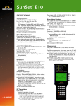
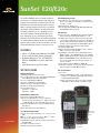
SunSet E20/E20c
®
The SunSet E20/E20c offers exceptional 2M testing features, including full duplex drop and insert
testing, international ITU measurements, DTE and
DCE datacom emulation, and multiplexer testing.
With its full transmission and service test features,
the flexible SunSet E20 offers an unparalleled set
of testing capabilities, as it is designed to test a
variety of networks, including Frame Relay, Cellular, Switching, Access, and simple Leased Line
Networks. The SunSet E20, in its handheld platform,
can troubleshoot and locate almost any problem to
optimize your technicians’ time and reduce the cost
of network downtime with this versatile test set.
FEATURES
• 2 Rx & 2 Tx, Bidirectional Monitor, Dual BERT
• G.821, G.826, M.2100, Alarms, Histograms,
• Protocols and Service Test: VF, ISDN, SS7,
MFC-R2, GSM/GPRS, V.5x, X.25, and Frame
Relay
• Jitter Measurement and Generation
SPECIFICATIONS
Connectors/Ports
2.048 Mbit/s bidirectional E1 interfaces
Line 1 Tx, Line 1 Rx, Line 2 Rx: 75Ω unbalanced BNC (f)
and 120Ω balanced/3-pin banana (CF)
Line 2 Tx: 75Ω unbalanced BNC (f)
Serial port: 8-DIN, RS-232C (V.24), DTE
Datacom interface: SCSI-36 pin connector
DC input for charging internal battery
Stereo headphones port
Connector: 3.5 mm jack
Impedance: 220Ω
Error/Alarm Injection
Code and/or bit error, and frame error; programmable
burst of 1 to 9999 error manually, or continuous rate
of 2x10⁻³ to 1x10⁻⁹
CRC-4, FAS, E-bit: Single error
Generate AIS, TS16-AIS (PCM-30), MFAS RAI (PCM-30),
FAS RAI (PCM-30 & 31) alarms
E1 General
Bit error test rates: 2.048 Mbit/s, N (contiguous) and M
(noncontiguous) x 64 kbit/s (N and M = 1 to 31)
Full duplex drop & insert to internal test circuitry, datacom interface, Nx64 kbit/s test pattern; or 64 kbit/s Alaw decoded and encoded VF channel to/from built-in
speaker or optional headphones (SS149)/microphone
Automatic configuration, Automatic Pattern Sync.
Line coding: HDB3, AMI
Framing: Unframed, PCM-30, PCM-31, with or without
CRC-4, conforms to ITU-T G.704
Programmable send frame words: Manual/auto E-bits,
MFAS word bit 5, bit 6 (MFAS RAI), bit 7, bit 8, MFAS
ABCD, FAS RAI, display & print, send and receive FAS/
NFAS and MFAS/NMFAS words, auto CRC-4 generation, freely settable Sa4, Sa5, Sa6, Sa7, Sa8, bits to 1
or 0 for 8 frames
Set idle channel code and ABCD bits (PCM-30)
V.54 channel loopback: Loop up, loop down according to
ITU-T V.54 and T1 E1.2/94-003 standards
E1 Transmitters
Clock source
Internal: 2.048 MHz (± 5 ppm). L1 Tx frequency adjustable over ± 50 kHz (± 25 kppm) with resolution
1 Hz (individually adjustable)
External: Through Line 1 Rx or Line 2 Rx, selectable
AMI, HDB3, or Sinusoidal TTL clock (Line 2 only)
Status/Alarm Indicators
Power and low battery LED indicators
16 dual-color LED indicators for Line 1 and Line 2
Current status & alarm history for: Signal, code error,
PCM-30, PCM-31, AIS, alarm, CRC detected, error
6 dual-color LED indicators for datacom (dual function
with Line 2)
Pattern Sync and bit error LED indicators
Test Pattern Generator
. . . a step ahead
General: All 1s, All 0s, Alt 1010, 1-in-4, 1-in-8, 3-in-24,
FOX
PRBS: 2n-1, n= 6, 7, 9, 11, 15, 20, 23; QRS, 220-1 ITU-T
Conforms to ITU-T O.151, O.152, O.153
Programmable: 10 user patterns, 24 bits long with user
definable labels
Selectable test pattern inversion
Automatic pattern synchronization
SunSet E20
monochrome
chassis
SunSet E20c
color chassis
SunSet E20/E20c
®
Loop: Recovered through Line 1 Rx or Line 2 Rx signal, selectable
AMI or HDB3
Pulse shape: 3.0 Vbp (± 10%) at 120Ω , 2.37 Vbp (± 10%) at 75Ω.
Conforms to ITU-T G.703.
E1 Receivers
Frequency: 2.048 Mbit/s ± 6000 bit/s
Input sensitivity
Terminate, Bridge: +6 to -43 dB with ALBO
Monitor: -15 to -30 dB resistive
Impedances
Terminate, Monitor: Line 1 and 2, 75Ω unbalanced, 120Ω balanced
Bridge
Jitter tolerance: Conforms to ITU-T G.823
Measurements
Error Type: Code, bit, CRC-4, FE, MFE, E-bit errors, slips
Typical error type reports: Error count, error rate, ES, %ES, SES,
%SES, UAS, %UAS, EFS, %EFS, AS, %AS
ITU-T G.821 Analysis, error type reports: Bit error & rate, ES, %ES,
SES, %SES, EFS, %EFS, UAS, %UAS, AS, %AS, SLIP, DGRM, %DGRM
ITU-T G.826 bidirectional analysis, CRC-4 block based; error type reports: EB, BBE, %BBE, ES, %ES, SES, %SES, UAS, %UAS, EFS, %EFS
ITU-T M.2100/550 analysis
Alarm statistics: LOS sec, LOF sec, AIS sec, FAS RAI sec, MFAS RAI sec
Frequency (Max hold, Min hold, Current), clock slips, wander
Signal level +5 to -36 dB
Print on event (Enable/Disable)
Print/save at timed interval (selectable up to 999 hr, 59 min) or at
end of test
Measurement duration continuous or timed; settable up to 999 hr, 59 min
Programmable measurement with selection of start TIME & DATE
Other Measurements
Pulse mask analysis
Scan period, 500 ns
On screen pulse shape display with G.703 pulse mask verification
– Displays pulse width, rise time & fall time in ns, %overshoot,
%undershoot
– Pulse mask storage and printing
Histogram analysis
Graphical display of accumulated errors (Bit, Code, E-bit, CRC,
FAS/MFAS) events for L1 Rx or L2 Rx and alarms (LOS, AIS, LOF,
FAS RAI, MFAS RAI, LOPS) events for L1 Rx and L2 Rx
Stores and prints 60 days by hour and 24 hours by minute
Storage of one complete histogram and current (base unit)
Storage of up to 15 histogram with user definable labels (requires
SA701)
Propagation delay
Measures propagation delay in microseconds & UIs (Unit Interval)
Maximum delay measurement (at 2.048 Mbit/s): 8 seconds
View received data
View live traffic 4096 bits long (16 full frames/one multiframe) in
PCM-30/31
Displays 8 timeslots per screen
Stores 64 scrollable screens, hold screen, print
Information displayed in ASCII, reverse ASCII, Binary, and HEX
View timeslot 16 (MFAS, NMFAS ABCD) in PCM-30: 16 Frames
View timeslot 0 (FAS, NFAS, CRC, MFAS/CRC words, E-bits Sa4 to Sa8,
A-bit) in PCM-30 and PCM-31: 16 Frames
Save test results of measurement runs, error and alarms events
Save up to 20 test results
Save up to 1000 events
Saved record can be locked
Simultaneously view bidirectional ABCD bits for 30 channels (PCM-30)
Jitter generation & measurement (SSE20c only): Refer to Jitter Option
specification sheet
E1 Voice Frequency
Companding: A-Law
View channel data 1 byte long (binary format)
Built-in microphone for talk
Monitor speaker or optional headphones (SS149) for line 1, 2, or both
with volume control
Signal-to-noise ratio measurement
Noise measurements with 3.1 kHz flat, psophometric weighting, 1010
Hz notch filters
Tone generation: 50 to 3950 Hz, res. 1 Hz; +3 to -60 dBmO, res. 1 dB
Level and frequency measurement: 50 to 3950 Hz, +3 to -60 dBmO
Coder offset and peak code measurements
ABCD bits monitor & transmit in selected channel (PCM-30)
Programmable ABCD states for IDLE, SEIZE, SEIZE ACK, ANSWER,
CLEAR BACK, CLEAR FORWARD, BLOCK ABCD; Default (Conforms
to Q.422) or 3 user defined setups
Labelling setup and display of Group I/II Forward, Group A/B Backward digits Q.441 or 3 user defined setups
Datacom Testing (SS600)
Connectors/Ports
Datacom Multiport via SCSI-36 connector
Adapters for DTE (male) and DCE (female) modes: V.35 (34 pinsISO 2593), V.11/X.21 (DB15-ISO 4903), V.24/RS-232 (DB25-ISO
2110), V.36/RS-449 (DB37-ISO 4902), RS-530 (DB25-ISO 2110),
G.703 codirectional (3-pin CF for Tx and Rx)
Y cable Adapter for MONITOR mode: V.35 (34 pins-ISO 2593),
V.11/X.21 (DB15-ISO 4903), V.24/RS-232 (DB25-ISO 2110), V.36/
RS-449 (DB37-ISO 4902)
Interfaces: V.35, V.11/X.21, V.24/RS-232, V.36/RS-449, RS-530, G.703
codirectional
Modes
DTE, DCE Emulation for all interfaces
Bidirectional data in service transmission monitoring (V.35, V.11/
X.21, V.24/RS-232, V.36/RS-449)
Rates
V.24/RS-232 Asynchronous: 50, 150, 300, and 600 bit/s, 1.2, 2.4,
4.8, 9.6, 14.4, 19.2, and 38.4 kbit/s, 6/7/8 data bits, 1/2 stop bits,
odd/even/none parity
V.24/RS-232 Synchronous: 300, 600, 1200, 2400, 4800, 9600 bit/s,
14.4, 19.2, 38.4, 48, 56, and 64 kbit/s
V.35, V.11/X.21, V.36/RS-449: 300, 600, 1200, 2400, 4800, 9600
bit/s, 14.4, 19.2, 38.4, and 48 kbit/s, Nx56 kbit/s, and Nx64 kbit/s
(N = 1 to 32)
G.703 codirectional: Nx64 kbit/s (N = 1 to 8)
Tx data clock selectable (internal or receive) for V.35, V.24/RS-232,
V.36/RS-449, G.703 codirectional
Clock polarity selectable (normal or inverse) for V.35, V.24/RS-232,
V.36/RS-449
Test pattern generator
V.24/RS-232 Asynchronous: 2047, 511, 127, 63, All 1s, All 0s, and
FOX (for 7 and 8 data bits)
All other modes: All available patterns supported (refer to the
main Test Pattern section)
Selectable test pattern inversion
Automatic pattern synchronization
Bit error injection
Measurements
ITU-T G.821 analysis, error type reports: Bit error count and rate,
ES, %ES, SES, %SES, EFS, %EFS, AS, %AS, UAS, %UAS, SLIP
Block error measurement: Received block count, error block
count, and rate
Measurement of Data Loss, Data Loss Seconds, Pattern Synchronization Loss, Pattern Synchronization Loss Seconds
Histogram analysis
Graphical display of accumulated errors (Bit, Loss of Pattern Seconds)
Stores and prints 60 days by hour and 24 hours by minute
Storage of one complete histogram and current (base unit)
Storage of up to 15 histograms w/user definable labels (requires SA701)
Propagation delay
Measures propagation delay in microseconds & UIs (Unit Interval)
Maximum delay measurement (at 2.048 Mbit/s): 8 seconds
Datacom timing analysis
Change of state of the following control leads is displayed and
recorded (Table or Graphic mode)
– V.24/RS-232 (Asynchronous: DTE, DCE; Synchronous: DTE,
DCE, MONITOR), V.35 (DTE, DCE, MONITOR), V.36/RS-449 (DTE,
DCE, MONITOR): RTS, CTS, DTR, DCD, RL, LL
– V.11/X.21 (DTE, DCE, MONITOR): C, I
Transmit control leads (selectable ON/OFF)
– V.24/RS-232 (Sync & Async), V.35, V.36/RS-449 (DTE): RTS, DTR,
RL, LL
– V.24/RS-232 (Sync & Async), V.35, V.36/RS-449 (DCE): CTS, DSR, DCD
– V.11/X.21 (DTE): C
– V.11/X.21 (DCE): I
Trigger on RTS, CTS, DTR, DSR, DCD, RL, LL; falling or rising edges
Storage capability
– Graphical mode: Last 40 seconds of captured control lead status
– Table mode: 100 pages of control lead state change and status
with timestamp
V.110 Testing (SW607)
Conforms to ITU-T V.110
V.110 analysis over E1 line
Test rate: Nx600 bit/s (N=1, 2, 4, 8, 16, 32), 48 kbit/s, 56 kbit/s
Bit error rate testing, V.110 FAS error, V.110 Parity Error, V.110 Frame
Sync Loss, V.110 Redundant Bit Error Measurements
V.110 framing status monitoring (Bits, S1, S3, S4, S6, S8, S9, X, E1 to E6)
Bit error and frame error injection
Programmable V.110 framing bits (S1, S3, S4, S6, S8, S9, X, E1 to E6)
Programmable Tx and Rx pattern
Modes: E1 Single (Send/Receive V.110 formatted channels inside
2.048 Mbit/s signal)
X.50 64 kbit/s Testing (SW606)
Conforms to ITU-T X.50 Division 2 and 3
Bit error rate testing with ITU-T G.821 analysis
Test rate: Nx600 bit/s, N = 1 to 8 within 64 kbit/s signal
Hitless bidirectional E1 64 kbit/s channel drop/insert to multiport
Standard or random selection of octets
View and transmit housekeeping bits A to H, and status S-bit
Programmable idle pattern, BERT & IDLE S-bit, X.50 signal (ABCD bits)
Bit or frame error injection
Histogram analysis
Modes
Datacom (64 kbit/s, X.50 formatted signal)
Muxtest (Test 2.048 Mbit/s/64 kbit/s multiplex)
MUX (Emulate 2.048 Mbit/s/64 kbit/s multiplexed within X.50 format)
E1 (Send/Receive X.50 formatted channels inside 2.048 Mbit/s signal)
C-bit Frame Testing (SW602)
Send and receive C-bits 2 through 15 (ESCAPE, 2 MB loops, loop 2
or loop 3, loop 2 instruction, loop 3 instruction, HDB3 command,
loop acknowledge, not defined, local fault, remote/line fault, C
frame loss, spare)
Bit level decoding
Loopback channel
Other Options (See Individual Specification Sheets)
Frame Relay Network Options (SW603 and SW603N)
Cellular Network Options (SW604, SW605, SW609, SW644, SW621,
SW622, SW629)
Access Network Options (SW610, SW611, SW612, SW613, SW614,
SW615, SW630, SW631)
Switching Network Options (SW601A, SW601E, SW640, SW641,
SW642, SW645, SW647, SW648)
X.25 Option (SW608)
Jitter Measurement Option (SW691) & Jitter Generation Option (SW692)
GENERAL
512 kbyte internal NVRAM data buffer
Internal Battery: 9-cell NiMH battery pack
Battery operation time: 4.5 hours nominal (for SSE20)
16 lines x 32 character graphic LCD with backlight (for SSE20)
240 x 320 dot STN Color Screen CFL Backlight (for SSE20C)
Heavy-duty long-lasting keyboard
8 Mbyte field upgradable PCMCIA memory card
2nd memory card slot for future expansion or unit memory storage
(Histogram and Protocol traces - requires SA701)
AC Adapter/battery charger: 100-240V 50/60 Hz
Languages: English, French, Italian, Spanish
Stores up to 10 user configurations (profiles) with alphanumeric labels
VT100 Remote Control (for SSE20 only)
Windows Remote Control and Remote Storage
TL1 Command Support
Printer/communication port: 8-DIN, RS-232 (V.24 DTE) serial port
Text: Standard ASCII escape sequence code
Graphics: Standard mode (dot matrix)
Operating temperature: 0˚C to 50˚C
Storage temperature: -20˚C to 70˚C
Humidity: 5% to 90% noncondensing
Size: 10.5 cm x 6.5 cm x 27 cm (approx)
Weight: 1.3 kg (approx)
ORDERING INFORMATION
SW611
Test Set
SW612
SSE20
SSE20C
SSE20FR
SSE20CFR
SunSet E20 Black & White
Configured with 2 Rx and 2 Tx 2.048 Mbps ports with BNC (f) &
3-pin banana (CF) connectors. CE Compliant.
SunSet E20c Color Screen
Configured with 2 Rx and 2 Tx 2.048 Mbps ports with BNC (f) &
3-pin banana (CF) connectors. CE Compliant.
Replace all standard labels (LED & Keypad) with French Labels
for SunSet E20.
Replace all standard labels (LED & Keypad) with French Labels
for SunSet E20c.
Each configuration includes:
Universal AC Charger (SS138E), Battery Pack (SS140), Protective
Cartridge (SW2504), Power Cord (SA155-EU), User’s Manual
(SS266), and Certificate of Calibration (SSE20CC). All other
accessories including datacom adapters must be purchased
separately.
Note 1:
Alternate power cord and alternate language for User’s Manual
can be substituted at N/C (please specify at time of order).
Hardware Options
SS600
SS600C
SSE20 Datacom Software/Hardware
Includes software for datacom testing (SW600DC) and datacom
cable (SS308). Requires additional adapters or adapters package
from Datacom Adapters section. For SSE20 B&W units only.
SSE20C Datacom Software/Hardware
Includes software for datacom testing (SW600DC) and datacom
cable (SS308). Requires additional adapters or adapters packages
from Datacom Adapters section. For SSE20C color units only.
Software Options
SW600TL1
SW600VT
SW600WIN
TL1 Remote Control
VT100 Remote Control for SSE20 only
Windows Remote Control for SSE20
Includes SS115D (DB9 to DIN8), SS122B (Null Modem), and
SA910-M which includes SA910-CD.
SW600WIN-C Windows Remote Control for SSE20C
Includes SS115D (DB9 to DIN8), SS122B (Null Modem), and
SA910-M which includes SA910-CD.
SW601A
VF Call Analysis
SW601E
VF Call Emulation
SW602
C-bit Analysis
SW603
Frame Relay
Includes manual SS266-1
SW603N
Frame Relay NNI
Requires SW603
SW604
GSM Voice and TRAU Access
Includes manual SS266-2
SW605
GSM Abis Protocol Analysis
Includes manual SS266-2
SW606
X.50 Analysis
Includes manual SS266-6
SW607
V.110 Analysis
Includes manual SS266-7
SW608
X.25 Analysis
Includes 1 Mb SRAM Memory Card SA701
SW609
GPRS Analysis
Includes SW629, SW621, SW622, and SA701 1 MB SRAM
Memory Card. Requires SW603 & SW605.
SW610
ISDN Monitoring & Call Emulation
Required for ISDN Protocols when ordering SW611-SW615.
Includes manual SS266-3
SW613
SW614
SW615
SW621
SW622
SW624
SW629
SW630
SW631
SW640
SW641
SW642
SW644
SW645
SW647
SW648
SW691
SW692
SA701
Note 2:
ETSI (EuroISDN) Protocol
Requires SW610
Aussi Protocol
Requires SW610
QSIG Protocol Monitor Only
Requires SW610
DPNSS Protocol
Requires SW610
DASS2 Protocol
Requires SW610
GPRS Abis Analysis-Ericsson BSS
Requires SW605 GSM Abis option
GPRS Abis Analysis - Nokia BSS
Requires SW605 GSM Abis option
GPRS A-bis Analysis – Nortel BSS
Requires SW605 GSM Abis option
GPRS Gb Analysis
Requires SW603 Frame Relay option
V5.x Monitoring
Includes manual SS266-5
3-timeslot V5.2 Monitoring
SW630 required
SS7 Analysis (MTP, SCCP, TCAP)
Required for SS7 Analysis when ordering SW641-SW646
Includes manual SS266-4.
TUP Analysis ITU Standard
Requires SW640
ISUP Analysis ITU Standard
Requires SW640
Mobile Application Part BSSAP (DTAP+MAP)
Requires SW640
ISUP Analysis Chinese Standard
Requires SW640
ISUP Analysis ANSI Standard
Requires SW640
SSUTR2 Protocol
Requires SW640
Jitter Measurement for SSE20C
Jitter Generation for SSE20C
1MB SRAM Card. Memory Card with battery back up to increase
the storage capacity of the test set
Software cartridges may be upgraded to include additional options at any time.
Upgrade Option
RE105
Retrofit Option (includes SW691 and hardware upgrade)
Warranty and Extended Options
SSE20W
Extended Warranty
Extends standard warranty to 3 years
Calibration Options
SSE20CC
SSE20CCM
Certificate of Calibration & Compliance
When requested after shipment of original order.
Measurement Data
Certificate of Compliance with Measurement Data when specified at time of order.
Accessories
SS101
SS104D
SS115
Carrying Case
Cigarette Lighter Adapter
NiMH Cigarette Lighter Battery Charger. Output 15.5 V DC
@2.5A (For use on SunSets equipped with NiMH battery only).
Printer Cable
DIN-8 to DB-25 RS-232C
SS122C
SS123A
SS123C
SS143B
SS149
SS266-8
2 Mbps Cables
SS210
SS211
SS212
SS216
SS217
SS220
SS221
SS223
SS225
SS227
SS228
SA331
SS434
SS436
Conversion Cable BNC (m) 75Ω to 3-pin banana CF
(m) 120Ω, 2 m
Cable BNC (m) 75Ω to BNC (m) 75Ω, 2 m
Conversion Cable Single Bantam (m) 120Ω to BNC
(m) 75Ω, 2 m
Conversion Cable BNC (m) 75Ω to BR2 (m) 120Ω, 2
m
Cable 1.6/5.6 mm (m) 75Ω to 1.6/5.6 mm (m) 75Ω, 2
m
Conversion Cable BNC (m) 75Ω to 1.6/5.6 mm (m)
75Ω, 2 m
Cable 3-pin banana CF (m) 120Ω to 3-pin banana CF
(m) 120Ω, 2 m
Cable BR2 (m) 120Ω to 3-pin banana CF (m) 120Ω, 2
m
Cable Bantam (m)120Ω to 3-pin banana CF (m)
120Ω, 2 m
Conversion Cable BNC (m) 75Ω to probe clips 120Ω,
2m
Cable 3-pin banana (CF) 120Ω to probe clips, 2 m
Adapter BNC 75Ω (m) to 1.6/5.6 mm 75Ω (f), 2 m
Cable RJ48 (m) 120Ω to two 3-pin Banana CF (m)
120Ω, 2 m
Conversion Cable RJ48 (m) 120Ω to two BNC (m)
75Ω, 2 m
Datacom Adapters
SS253
SS253C
SS253T
SS253Y
SS254
SS254C
SS254T
SS255T
SS255Y
SS256B
SS262-B
SS262C-B
SS262T-B
SS267
SS267C
SS267T
SS267Y
SS600DCC
SS600DCY
Replacement
SW2504
SS123B
SS138E
SS140
SS266
SS266-1
SS266-2
SS266-3
SS266-4
SS266-5
SS266-6
SS266-7
SS266-10
SS266-11
SA910-M
SS308
SA155-EU
SA155-NA
SA155-UK
Protective Cartridge
Protects the 2nd card slot when empty
Carabiner Hook For SunSet Jacket
SunSet AC Adapter 100-240 VAC, 50/60 Hz input,
3-prong input, output 15 VDC @ 3.3A. Only for use
with SunSets equipped with NiMH battery pack.
High Capacity NiMH Battery Pack. 9-Cell, 10.8 VDC,
1.8 Ahr
SunSet E20/E20c User’s Manual, English
User’s Manual Insert for Frame Relay
User’s Manual Insert for GSM
User’s Manual Insert for ISDN
User’s Manual Insert for SS7
User’s Manual Insert for V5.1/V5.2
User’s Manual Insert for X.50
User’s Manual Insert for V.110
User’s Manual Insert for E20 TL1 Remote Control Manual
User’s Manual Insert for X.25
SunSet Remote Control Manual
Includes CD with latest Windows software
Datacom Cable
SCSI-36 (m) to DB-37 (f) Interface cable, 2 m
Power Cord
2-prong power cord plus ground for use in Europe
(Except United Kingdom)
Power Cord
3-prong power cord for use in Latin America, North
America, and Asia
Power Cord
3-prong power cord for use in United Kingdom
IS
www.sunrisetelecom.com
LE
E TE C O M
N C.
IS
90
O
Note: Specifications subject to change without notice. All product and
company names are trademarks of their respective corporations.
© 2004 - 2005 Sunrise Telecom, Inc. Do not reproduce, redistribute or repost
without written permission from Sunrise Telecom. All rights reserved.
MKS-22013-001 REV. A00 May 2005
302 Enzo Drive
San Jose, CA 95138 USA
ph 1 408 363 8000
fax 1 408 363 8313
[email protected]
,I
X.21/V.11 DTE/DCE Interface Adapters Set
DB37 to ISO 4903 DB15 connectors
X.21/V.11 DCE Interface Adapter
DB37 to ISO 4903 DB15 connectors
X.21/V.11 DTE Interface Adapter
DB37 to ISO 4903 DB15 connectors
X.21/V.11 Datacom Monitor Y-cable
DB37 to male and female ISO 4903 DB15 connectors
RS-232/V.24 DTE/DCE Adapter Set
DB37 to ISO 2110 DB25 connectors
RS-232/V.24 DCE Interface Adapter
DB37 to ISO 2110 DB25 connectors
RS-232/V.24 DTE Interface Adapter
DB37 to ISO 2110 DB25 connectors
SS255C
0
SS122B
SS255
RS-232/V.24 Datacom Monitor Y-cable
DB37 to male and female ISO 2110 DB25 connectors
RS449/V.36 DTE/DCE Adapters Set
DB37 to ISO 4902 DB37 connectors
RS449/V.36 DCE Interface Adapter
DB37 to ISO 4902 DB37 connectors
RS449/V.36 DTE Interface Adapter
DB37 to ISO 4902 DB37 connectors
RS449/V.36 Datacom Monitor Y-cable
DB37 to male and female ISO 4902 DB37 connectors
G.703 64 Codirectional Interface Adapter
DB37 to CF 3-pin banana TX and RX connectors
RS-530 DTE/DCE Interface Adapter Set
DB37 to DB25 connectors
RS-530 DCE DB37 to DB25 connectors
RS-530 DTE Interface Adapters
DB37 to DB25 connectors
V.35 DTE/DCE Adapter Set
DB37 to ISO 2593 34 pin connectors
V.35 DCE Interface Adapter
DB37 to ISO 2593 34 pin connectors
V.35 DTE Interface Adapter
DB37 to ISO 2593 34 pin connectors
V.35 Datacom Monitor Y-cable
DB37 to male and female ISO 2593 34 pin connectors
Datacom Adapters Package
Includes datacom adapters SS253, SS254, SS255,
SS256B, SS262-B, and SS267
Datacom Adapters Y Package
Includes datacom adapters SS253, SS253Y, SS254,
SS254Y, SS255, SS255Y, SS256B, SS262-B, SS267,
and SS267Y
38
SS118C
SS254Y
R
SS117
SS118B
Printer Cable
DIN-8 to DB-9 (m) RS-232C with Full Handshaking.
Included when SS118B/C is ordered.
Printer Paper 5 rolls, for SS118B/C/D/E
High Capacity Thermal Printer internal rechargable
battery. Includes (SS115D) for connection to
SunSet, and 110 VAC charger.
High Capacity Thermal Printer with internal rechargable battery. Includes (SS115D) for connection to
SunSet, and 220 VAC charger.
Null Modem Adapter
DB-9 (f) to DB-9 (f) with Full Handshaking
Null Modem Adapter
DB-25 (f) to DB-25 (f) with Full Handshaking
SunSet Jacket
Provides additional weather protection for SunSets.
Includes Carabiner Hook (SS123B).
SunSet Jacket, Large
Provides additional weather protection for SunSets.
Only for use with Rubber Holster (SS143B). Includes
Carabiner Hook (SS123B).
Rubber Holster for SSE20 only
Protective rubber covering with integrated instrument stand. Compatible with SS123C.
Headphone
SSE20 Service Manual
SUN
SS115D
01 - A6