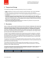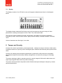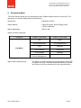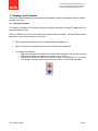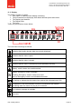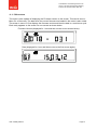
1
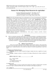
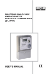
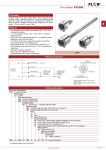
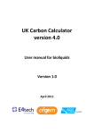
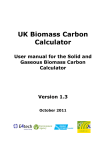
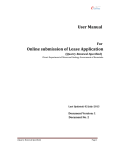
Confidential © Itron Metering Solutions UK Ltd 2014. All rights reserved Itron Metering Solutions UK Ltd, Manchester M32 0XX ‘s’ Series (UK) Smart Gas Meter User & Safety Manual G4 RF1 sV ZB User & Safety Manual Page 1 Confidential © Itron Metering Solutions UK Ltd 2014. All rights reserved Itron Metering Solutions UK Ltd, Manchester M32 0XX Table of Contents Table of Contents.............................................................................................................................. 2 1 Introduction ................................................................................................................................ 3 1.1 ATTENTION ....................................................................................................................... 3 2 Important Safety Instructions ..................................................................................................... 4 3 EC Directives ............................................................................................................................. 4 4 Transport and Storage ............................................................................................................... 5 5 Description ................................................................................................................................. 5 6 Characteristics ........................................................................................................................... 6 7 Construction............................................................................................................................... 7 7.1 Dimensions ......................................................................................................................... 7 7.2 Display ................................................................................................................................ 8 8 Tamper and Security.................................................................................................................. 8 9 Communication .......................................................................................................................... 9 10 Prepayment and Credit Operation ........................................................................................ 10 10.1 Tariff ................................................................................................................................. 10 10.2 Credit Mode ...................................................................................................................... 10 10.3 Prepayment Mode ............................................................................................................ 10 11 Displays and Controls .......................................................................................................... 11 11.1 Display Operation ............................................................................................................. 11 11.2 Display .............................................................................................................................. 12 11.3 F/W versions ..................................................................................................................... 13 12 Firmware Update .................................................................................................................. 14 13 Battery.................................................................................................................................. 14 13.1 Battery Life ....................................................................................................................... 14 13.2 Battery Safety ................................................................................................................... 14 14 Battery/Communication Module Exchange ........................................................................... 14 15 Functional Safety.................................................................................................................. 14 16 Marking ................................................................................................................................ 15 17 Installation ............................................................................................................................ 15 17.1 Installer. ............................................................................................................................ 16 17.2 Pressure. .......................................................................................................................... 16 17.3 Location. ........................................................................................................................... 16 17.4 Safety ............................................................................................................................... 16 17.5 Transportation................................................................................................................... 16 Note: The meter described in this document is in development. The content of this document is subject to change and will only be confirmed when the development is complete. User & Safety Manual Page 2 Confidential © Itron Metering Solutions UK Ltd 2014. All rights reserved Itron Metering Solutions UK Ltd, Manchester M32 0XX 1 Introduction This document describes and defines the Smart Gas meter for the UK market. 1.1 ATTENTION “s” Series Meter has an internal valve. After each automatic shut-off of gas supply by the meter: 1. Ensure that all gas appliances are turned off (command button in closed position). 2. AFTER STEP 1 ONLY, proceed with meter opening according to the procedure described in this user manual. 3. WAIT 3 minutes (180 seconds) minimum before turning back on all the gas appliances, this needs to be according to the safety instructions required by the manufacturer. Battery Warning This product contains a Lithium Battery Fire, explosion and severe burn hazard. Do not recharge, short circuit, crush, disassemble, heat above 100°C (212°F), incinerate or expose contents to water. Do not solder directly to the cell. Respect the storage and disposal recommendations. Safety Warning: Static Hazard – Clean the meter only with a damp cloth Keep this manual easily accessible for all installers. Please respect all national rules for installation, operation and service of gas meters. User & Safety Manual Page 3 Confidential © Itron Metering Solutions UK Ltd 2014. All rights reserved Itron Metering Solutions UK Ltd, Manchester M32 0XX 2 Important Safety Instructions The following important safety instructions have to be ensured: All national rules for installation, operation, inspection and maintenance of gas meters must be respected. The ‘s’ Series smart gas meters are designed to measure gases of the 1st, 2nd and 3rd gas family as specified in EN437 as well as various filtered and noncorrosive gases. If aggressive gases are to be measured, please contact Itron for specific advice. If there is a risk of internal or external corrosion, inspect the device regularly. If the device is clearly affected by corrosion, put it out of use. The operating conditions indicated on the nameplate, especially maximum admissible operation pressure and flow rate have to be respected. The device is not designed to withstand earthquakes and floods. Repairs of the device must be performed by properly instructed skilled personnel only. Repairs must be followed by a leakage test with 1.5 x maximum pressure. The guarantee only covers repairs done by Itron. Relieve internal pressure completely before removing the device. Ensure proper ventilation because of possible escapes of residual gas. Cap the inlet/outlet connections. For installation, follow the instructions mentioned in the section “Installation and Commissioning”. 3 EC Directives The meter meets the requirements and is marked in accordance with the following directives: Directive 2004/22/EC (MID) of the European Parliament and of the Council of 31 March 2004 on measuring instruments Directive 94/9/EC (ATEX) of the European Parliament and of the Council of 23 March 1994 on the approximation of the laws of the Member States concerning equipment and protective systems intended for use in potentially explosive atmospheres: Device group and category II 3G Gas group IIA Temperature class T3 Ambient temperature(1) -25ºC to +55ºC Directive 1999/5/EC (RTTE) of the European Parliament and of the Council of 9 March 1999 on Radio and telecommunications terminal equipment The batteries comply with the battery directive: Directive 2006/6/EC (Batteries directive) of the European Parliament and of the Council of 6 September 2006 on batteries and accumulators and waste batteries User & Safety Manual Page 4 Confidential © Itron Metering Solutions UK Ltd 2014. All rights reserved Itron Metering Solutions UK Ltd, Manchester M32 0XX 4 Transport and Storage For transport and storage, the following instructions have to be considered: Before installation, the meter must be checked for possible damage. Never install a damaged meter. The caps fitted at the inlet and outlet connections must stay in place until installation. Storage temperature range of -40° to +70°C (4 hours maximum between +55° and 70°C) has to be ensured. Handle gas meters with care during transport. Shock must be avoided. On receipt, carefully examine the shipping container and the meter itself for any external damage. Any visible damage should be reported to the carrier. Always keep the meter vertical during transport and installation. Make sure it is well fixed on the lorry and handled without dropping. Please note that the packing material of the meters shall be recycled. Do not remove any seal from the meter; you will invalidate the guarantee of the product and maybe the metrological approval of the meter. 5 Description Itron’s ‘s’ Series meter is a result of combining more than 100 years of diaphragm meter engineering experience with latest high quality electronic and communication technologies. As a part of the endto-end smart metering system ’s’ Series is the latest development. It consists of a gas containing steel case, enclosing a diaphragm measuring unit and shut off valve, connected to an electronics unit which is enclosed in a housing mounted on the outside of the steel case. The measuring unit is latest version of the field proven 2 litre RF1 diaphragm unit, which has been used in large volumes for many years and in many different environments. The shut off valve is designed to minimise the time and energy involved in operation in a way that the effect on battery life is less critical and also simplify user operation. It is located in the outlet of the measuring unit, and consists of an integrated electronic and mechanical unit. It is connected to the external electronics unit through the steel case, whilst still enabling the meter to meet the high ambient temperature requirement. The electronics unit includes interchangeable batteries and communication modules, located under a sealed cover. The electronics unit uses a proven optical detection in order to provide accurate, low power and bi-directional functionality. The modular communications interface design offers the possibility to choose from a range of different communication protocols and interfaces as per the customer requirements. The normal interface for UK is Zigbee Smart Energy. The meter is connected to the gas supply through standard size UK bosses, with the outlet boss (on the right when facing the meter) having a pressure test point incorporated. “s” Series meter is available in the following variants and sizes for UK. Product Name RF1 sV ZB User & Safety Manual Available Sizes G4 Description RF1 meter with a ZigBee communication Page 5 Confidential © Itron Metering Solutions UK Ltd 2014. All rights reserved Itron Metering Solutions UK Ltd, Manchester M32 0XX 6 Characteristics Properties Technical Data Meter sizes G4 Cyclic volume 2.0L ±0.1L Transportation Temperature -25°C to +55°C, +70°C for up to 8 hours Storage and Operating Ambient Temperature -25°C to +55°C Degree of Protection IP54 (EN 62059) Operating Humidity <= 93%, between -25°C and +40°C <= 90%, between +40°C and +55°C Gas Temperature -25°C to +55°C Gas type Groups L and H (2nd family of EN437) and LPG Gas conditions Clean and non-condensing gas Gas Pressure 0-100 mbar Gas Flow rates In accordance with EN1359 table 1 G4 Qmin 0.04m3/hr, Qmax 6m3/hr Pressure Absorption <2 mbar ATEX Zone 2 : Maintenance Field changeable battery and communication modules Battery Lithium batteries with an average lifetime of minimum 15 years under reference conditions Accuracy Class 1.5 Display LCD with icons and 9 segment characters Mechanical Environment M1 Electronic Environment E2 Color Grey User & Safety Manual II 3G Ex ic ia IIA T3 Gc Page 6 Confidential © Itron Metering Solutions UK Ltd 2014. All rights reserved Itron Metering Solutions UK Ltd, Manchester M32 0XX 7 Construction 7.1 Dimensions The meter has bosses to BS 746:2005+A1:2009 spaced at 6” pitch and is suitable for installation in accordance with BS 6400-1:2006 and for use in meter boxes to BS8499. Meter Location: User & Safety Manual Indoor or sheltered outdoor, protected from rain and sun Atex zone 2, MID EMC E2 Page 7 Confidential © Itron Metering Solutions UK Ltd 2014. All rights reserved Itron Metering Solutions UK Ltd, Manchester M32 0XX 7.2 Display The display consists of an LCD with icons and 9 segment characters as shown in the diagram below. The display shows measured Gas Volume (m3) and can sequence through a range of other parameters, including consumption in kWh, Tariff, Time, Date and Credit. The icons are used to indicate low credit, valve status, valve able to be opened, low battery, Emergency Credit, Communication status, legally relevant display, message available, monetary value. Volume characters are 8mm high, 6 mm wide. 8 Tamper and Security Access to the meter is protected by metrological seals – attempts to tamper will leave visible marks. In addition detection of opening of the metrological part is detected electronically and reported as an alarm Access to the battery/communications department is protected by utility seal and is separately detected and reported electronically. Battery change does not require any change to metrology seals. The meter metrology is able to operate correctly in normal magnetic fields and is able detect and report high magnetic fields which may affect metrology. The meter monitors ambient temperature and will detect and report attempts to tamper by excess ambient temperature. User & Safety Manual Page 8 Confidential © Itron Metering Solutions UK Ltd 2014. All rights reserved Itron Metering Solutions UK Ltd, Manchester M32 0XX 9 Communication The meter has an optical port for maintenance and a Zigbee Radio module for normal use. The optical port is normally disabled after manufacturing. Optical Port: EN62056-21:2002 Zigbee Module Zigbee Pro stack, Smart Energy profile 2.4 GHz ISM band Zigbee Application SEP1.2 with Zigbee Clusters supported: End point Cluster - Client Side Cluster - Server Side Time Basic Key Establishment Key Establishment Price Metering TOU Calendar Prepayment OTA Upgrade Message Gas Meter Device Management Zigbee Mirror/Sleepy device: User & Safety Manual The Meter is a sleepy end device and requires the Client ESI to support mirroring. The Meter wakes periodically to update the values in the mirror and check for any required actions Page 9 Confidential © Itron Metering Solutions UK Ltd 2014. All rights reserved Itron Metering Solutions UK Ltd, Manchester M32 0XX 10 Prepayment and Credit Operation The meter can operate in Credit mode and Prepayment mode in accordance with the tariff. 10.1 Tariff The meter is able to operate according to tariffs, defined in £p/kWh. The Meter utilises the defined Calorific Value to determine gas use in kWh and hence the applicable charge, based on the volume measured. 10.2 Credit Mode In Credit mode the valve is open and the meter uses the tariff information to estimate the cost of gas consumed in the current billing period. 10.3 Prepayment Mode In Prepayment mode, the meter maintains a credit balance. User & Safety Manual Page 10 Confidential © Itron Metering Solutions UK Ltd 2014. All rights reserved Itron Metering Solutions UK Ltd, Manchester M32 0XX 11 Displays and Controls The meter display displays the current status and together with the two buttons may be used to manage the meter. 11.1 Display Operation The display is normally OFF and turns on when a button is pressed, turning OFF again after 30 seconds without activity. When the Display is OFF the first button press switches ON the Display. The first Display shown depends on the mode and status of the meter: When configured in credit mode, the Display starts on Display A0 When configured in prepayment mode, the meter starts on Display J0 To navigate the displays: o Make short presses to the buttons to move within a specific row, e.g. A0 to A1 etc. o Make longer presses to change the column e.g. A to B etc. o The Blue “X” button increases the number or letter of the alphabet (1 to 2, A to B) o The Orange “triangle” button decreases the number or letter of the alphabet User & Safety Manual Page 11 Confidential © Itron Metering Solutions UK Ltd 2014. All rights reserved Itron Metering Solutions UK Ltd, Manchester M32 0XX 11.2 Display The display consists of 4 parts: The “index” to indentify which display is showing The 9 Characters on the display with related decimal points and colons The Display type identifier The Display units The Icons These are positioned as shown below: The icons have meanings as follows: Indicates that legally relevant data are currently displayed Indicates that the valve is open Indicates that the valve is closed Indicates that the valve is released (may be opened by the user) Steady: credit is below low credit threshold Steady: Emergency credit is available Flashing: Emergency credit is ready to be used No Icon Emergency credit is not available/exhausted Is flashing to indicate that the battery has reached his estimated end of life is displayed, if the communication module is connected to the network. Is flashing when the meter is trying to join a network Is on when a message is available Not used User & Safety Manual Page 12 Confidential © Itron Metering Solutions UK Ltd 2014. All rights reserved Itron Metering Solutions UK Ltd, Manchester M32 0XX 11.3 F/W versions The meter is also capable of displaying the Firmware version on the screen. This can be seen in Menu G1 of the meter. The date when the current firmware was loaded in the meter is also visible. The screen in menu G1 first displays the firmware version and then the date in a continuous cycle. Each entity appears on the screen for one second as shown below. Firmware Version (displayed for 1 sec and then moves to next screen below): Date (displayed for 1 sec and then moves to the first screen again): User & Safety Manual Page 13 Confidential © Itron Metering Solutions UK Ltd 2014. All rights reserved Itron Metering Solutions UK Ltd, Manchester M32 0XX 12 Firmware Update The meter is able to update its firmware via “Over the Air Update” using the defined Zigbee SE process. The update process is managed with controls to verify the completeness and correctness of the firmware before a change to the updated firmware. The meter continues to measure during the update process. 13 Battery The meter contains Lithium batteries. 13.1 Battery Life The life of the batteries is dependent on the use of the meter, including the frequency and length of communications. The battery life in defined conditions is 15 years 13.2 Battery Safety The battery selected forms part of the Atex, RTTE and MID approvals for the Meter. The battery MUST NOT be changed in a hazardous area. The battery must only be changed by trained operator. The battery uses lithium construction, and therefore waste disposal needs to be considered carefully. The following warning applies to the battery: “Warning: Do not recharge, open, heat or dispose of in fire. Do not drop, damage, immerse, force discharge or short circuit”. Therefore as applied to the Meter: “Warning: Do not open, heat or dispose of in fire. Do not drop, damage, or immerse”. 14 Battery/Communication Module Exchange The Batteries and Communication module may be exchanged in the field by a Meter Worker only. The cover is protected by a seal to prevent unauthorised access. 15 Functional Safety The meter is designed to EN61508:2010 Functional safety of electrical/electronic/programmable electronic safety-related systems, SIL2 requirement. User & Safety Manual Page 14 Confidential © Itron Metering Solutions UK Ltd 2014. All rights reserved Itron Metering Solutions UK Ltd, Manchester M32 0XX 16 Marking The Meter is marked with the markings required by the MID, RTTE, Atex directives and includes the meter number information and barcode. The meter bears on its front face resistant and secure markings that include: Logo/name of manufacturer Accuracy class (1.5) Maximum and minimum ambient temperature Maximum approvable gas overpressure Qmax, Qmin and Qt Meter type Cyclic volume Numbers of the EC-Type Examination Certificate (reference to directives : MID) CE-marking plus additional metrology marking Declaration of measuring unit [m³] in immediate proximity to the digit with the lowest value of the totalizing unit ATEX marking Equipment identifier Itron serial number Year of manufacturing Manufacturer site Customer specific information (serial number including Bar Code in customer defined format) 17 Installation The Meter must be installed in the network, in a manner that complies with the requirements of: Gas Acts, Various Health and Safety at Work Act Gas Safety (Management) Regulations Gas Safety (Installation and Use) Regulations OFGEM Codes of Practice 1A and/or 1C. The installation must be made with the Meter upright (within 10°of vertical in both planes), below a Meter support bar Any necessary meter pipe work, soldering, drilling or other installation works must be completed before the meter is unboxed, uncapped and fitted. The commissioning operation takes place after a Meter has been installed in the network. The Meter is intended for installation in domestic premises. The Meter must only be installed with the occupier present. Installations must be made in accordance with BS6400. User & Safety Manual Page 15 Confidential © Itron Metering Solutions UK Ltd 2014. All rights reserved Itron Metering Solutions UK Ltd, Manchester M32 0XX 17.1 Installer. The installer must be suitably qualified to complete the installation safely, and must instruct the occupier of the premises in the safe operation of the Meter. Additionally, the person fitting the Meter MUST be a "Competent Person" (that is, registered Gas Safe, or similar/successors ). The Meter installer must be registered with OFGEM as an OAMI (Ofgem Accredited Meter Installer). 17.2 Pressure. Pmax = 100 mbar Normal Working Pressure = 21 mbar The Meter will impose less than 2 mbar pressure drop at 6 m³/hr (when the Valve is open) 17.3 Location. The Meter may be installed indoors in a suitably ventilated area, or in an outdoor Meter box constructed for the installation of Gas meters, and compliant with the requirements of BS6400, provided that the door is fitted to the box and is kept closed at all times, excepting when interaction with the meter is necessary. 17.4 Safety The safe operation of the Meter and installation may be impaired if the Meter is damaged in any way. The Meter must not be punctured, drilled, distorted, deformed, cracked, dropped, exposed to temperatures, flow or gas pressure/differential pressure/gas system outside specified range, soaked, submerged, radiated or otherwise interfered with. If the Meter has or may have suffered from any of these factors or there is any indication of damage or interference to the Meter (including damage to seals or fixings) the safety and integrity could be impaired and it must not be installed or if already installed must be removed. See also Section 13.2 regarding the battery. 17.5 Transportation The Meter contains Lithium Batteries and must always be transported appropriately. See Section 13 for details about the batteries. User & Safety Manual Page 16