1
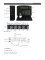
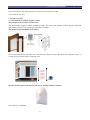
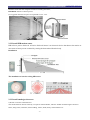
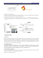
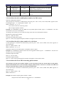
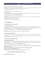
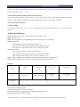
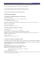
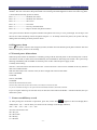
G50 GSM alarm user manual-PATENTED
DESIGN
G50 GSM alarm User Manual
Ver 1210 2008-12-10
-1-
G50 GSM alarm user manual-PATENTED
Contents
1.Instruction
1.1 Function & Feature
1.2 Specification
1.3 Standard packing list
1.4 Main unit layout
2. Installation
2.1 Install main unit
2.2 Install accessories
2.2.1 Install door/window magnetic contact
2.2.2 Install PIR motion sensor
2.2.3 Install smoke/gas detectors
3. Operation steps
3.1 Turn on
3.2 Keypad setting
3.2.1 Password verification
3.2.2 Set/delete/check 6 mobile phone numbers for SMS alarm.
3.2.3 Set/delete/check 5 phone numbers for call alarm
3.2.4 Set/delete/check 1 SMS forwarding phone No.
3.2.5 Recording voice
3.2.6 Change passwords
3.2.7 Change ID
3.2.8 Set date & time of main unit
3.2.9 Set/cancel fixed arm/disarm/partial arm time
3.3 Learning code
3.3.1 Learn/cancel remote control.
3.3.2 Learn/cancel wireless sensors
3.3.3 Cancel all wireless accessories.
3.4 Exit setting
4. Zone classfication
5. SMS command
5.1 Set/delete 5 mobile phone numbers for SMS alarm
5.2 Set/delete 5 phone numbers for call alarm
5.3 Set/delete 1 SMS forwarding phone No.
5.4 Change password
5.5 Arm/disarm
5.6 Change zone name
5.7 Set/inquiry/delete independent partial arm zone.
5.8 Inquire arm/disarm status
5.9 Inquire external power status
5.10 Relay output
6. Usage
6.1 Arm/disarm
6.2 Handfree mobile phone
6.3 Door/window open reminder
6.4 Sensors low voltage reminder.
6.5 Deal with alarm
6.6 Emergency alarm
6.7 External power failure alarm
6.8 Delay alarm setting
7. Events record/History record
-2-
DESIGN
G50 GSM alarm user manual-PATENTED
DESIGN
1.Instruction
The alarm system adopts SMS data transmission and voice platform of GSM network to send control command
and receive alarm remotely, which is designed for house, office, supermarket etc indoor use. It will call & send
alarm SMS to user cellphones immediately when any sensor is triggered. The system can also be used as handfree
mobile phone for two-ways communication.
The LCD on the alarm Main unit can show the time, data, operation guide, alarm details and status of arm, disarm,
GSM signal, power etc. With the LCD, all the operation and program are visual and intuitive.
The system with human kind voice guide and can be recorded into all different kinds of languages and work well
all over the world. The low-voltage warning for sensors and door/window opened reminder make use more
friendly. The function in details as follows.
1.1 Function & Feature
● Color LCD screen, keypad with blue background light
● Maximum 4 wireless panic buttons, 4 wireless fire detectors,
16 remote controllers, 32 wireless intruder detectors.
● Maximum 8 wired zones. Zone 1 and zone 2 for wired door/window magnetic contact, which will remind you if
the door/window is open.
● Send alarm SMS to 5 preset mobile phone No.
● Auto dial 5 preset user phone No.
● Forward mobile company SMS to user automatically.
● Work with monitoring center, such as police station.
● One relay output control DVR/Home appliance remotely.
● Sensors low voltage reminder
● Learning code for wireless accessories
● Voice operation reminder.
● Recording voice
● Three level password management.
● With independent partial arm function
● Zone classification prevent inside thieves effectively.
● Two fixed arm time, two fixed disarm time and one fixed partial arm time
● 220 wireless address encode reduce the rate of same code greatly.
● SMS control & program
● SMS modifies wireless zones name.
● Arm/disarm by keypad, remote controller, phone or SMS
● Call the main unit to listen in status whenever.
● Internal MIC or external high sensitivity MIC (optional)
● Internal GSM antenna or external antenna(optional)
● Main unit with tamper switch
● External power failure alarm.
● Entry delay alarm
● Two-way communication
-3-
G50 GSM alarm user manual-PATENTED
● Handfree mobile phone.
1.2 Specification
Main unit
1) GSM frequency
900/1800MHz, 850/1900MHz (optional)
2) External power failure alarm
Start-time: less than 5s
3) Alarm response time
Less than 10s (GSM in normality)
4) Delay arm time: 30s
5) Power
Power requirement:AC110-220V 50Hz or 60Hz; DC9V
Working power consumption:less than 3W
Standby battery:DC7.4V, 700MAH
Standby battery working hours: more than 10 Hours
6) Working conditions
Operating temperature:-20℃ ~ 60℃
Humidity:20% to 95%
Accessories:
1)Remote controller
Power Requirement:DC12V
Transmitting Freqency:315±0.2Mhz/433±0.2Mhz
Transmit Distance:more than 80m (no obstacle)
Coding type: Learning code.
Lifespan of battery:half year (trigger 20 times everyday)
2)Wireless Door/window magnetic contact
Power requirement:DC=12V-8.4V(23A DC=12V battery inside)
Wireless Freqency:315±0.2Mhz/433±0.2Mhz
Transmit Distance:more than 80m (no obstacle)
Coding type:Learning code.
Lifespan of battery:half year (trigger 20 times everyday)
Low voltage reminder value:≤10.5V
3)Wireless PIR motion sensor
Power Requirements:DC9V
Wireless Freqency:315±0.2Mhz/433±0.2Mhz
The largest coverage:12*12m
Visual Angle:110°
Bracket Adjustable Angle:-45° to +45°(Horizontal line)
Bracket Adjustable Angle:-15° to +45°(Vertical line)
-4-
DESIGN
G50 GSM alarm user manual-PATENTED
Coding Type:Learning code
Lifespan of battery:half year (trigger 20 times every day)
Low voltage reminder value:≤2.2V
Siren
Power Requirements:DC12V
Volume:More than 110db
Color:black
1.3 Standard packing list
Main unit x 1
GSM antenna x 1
Remote control x 2
Wireless door/window magnetic contact x 1
Wireless PIR sensor x 1
Wired siren x 1
AC/DC adapter x 1
User manual x 1
Optional wired & wireless accessories
Door/window magnetic contact
Magnetic steel scrolling door sensor
PIR motion sensor
Curtain PIR sensor
Ceiling PIR sensor
Vibration sensor
Smoke sensor
Gas sensor
Glass break sensor
Remote control
Panic button
Speaker
External high sensitivity MIC
Infrared Beam detector
Infrared Fence detector etc
Optional sirens
Wired & wireless indoor siren & strobe siren
Wired & wireless outdoor strobe siren
-5-
DESIGN
G50 GSM alarm user manual-PATENTED
1.4 Main unit layout
Main unit back:
2. Installation
2.1 Install main unit
a) Insert a valid SIM card into main unit
Note: Make sure the SIM card is valid.
-6-
DESIGN
G50 GSM alarm user manual-PATENTED
DESIGN
b) Install the GSM external antenna
Note: The main unit with internal antenna itself and external antenna available.
c) Fix and hide main unit
2.2 Install accessories
2.2.1 Install the door/window magnetic contact
The principle of door/window contact sensor
The door/window magnetic contact includes two parts. The sensor will send the wireless signal to main unit
immediately when the two parts depart more than 15-30mm.
The picture of the installation is as follows,
In some circumstances the wired & wireless Infrared Fence detector is more appropriate than magnetic sensors. i.e.
veranda, picture window balcony, boundary wall.
Wired or wireless glass break detector can also be used for window (see below)
The sensitivity is adjustable
-7-
G50 GSM alarm user manual-PATENTED
DESIGN
Wireless scroll steel door magnetic sensor for scrolling steel door,
Installation: Please see below picture
It is triggered when the two parts are separated to 3cm - 5cm.
2.2.2 Install PIR motion sensor
PIR refers to passive Infra-red. A Passive Infra-red Sensor is an electronic device that detects the motion or
movement of some person or animal by sensing the heat emitted from the body.
Installation:
The installation of wireless ceiling PIR sensor
2.2.3 Install smoke/gas detectors
a) Wired or wireless smoke detector
This smoke detector detects smoke by a couple of infrared diodes, which is suitable for detecting the smoke in
house, shop, hotel, restaurant, office building, school, bank, library and storehouse etc.
-8-
G50 GSM alarm user manual-PATENTED
DESIGN
b) Wired or wireless gas detector
The product is ceiling mounted gas detector with high stability. It is used for detecting leaking gas and suitable for
the safety of residential house, villas, hotels, boarding house etc.
Detecting the gas heavier than air: installation height from floor: 0.3m ~ 1.0m, semi-diameter to gas sources: <
1.5m; detecting the gas lighter than air: installation height from ceiling 0.3m ~ 1.0m, semi-diameter to gas sources:
< 1.5m.
Open or close manipulator
/Test button
Power LED (green)
Working LED
3. Operation steps
3.1 Turn on
Make sure that the power supply is connected correctly, and turn on the main unit power switch. It will search the
GSM network automatically within 25 seconds after it is started. Then the LCD display turns on and shows the
model No. and the status of arm, disarm, GSM signal etc. GSM network is normal when LED indicators under the
disarm button flash regularly. When the external power is normal, the LCD background light keeps on. If there is
no external power, it is off automatically after operation.
3.2 keyboard setting
Note: When setting by the keyboard, every time you press the button you will hear “di” sound for
confirmation. Please press it again if there’s no voice. Press “CLS” button before inputting “OK” to
cancel the input numbers. If the LCD display shows “FAIL”, check and reset it.
3.2.1 Password verification
Press “SET”, input password + OK, then you will hear “di,di” sound for confirmation. While “SET” and “SMS”
appear on LCD display, it means that the password is correct.
Total three level password protection
-9-
G50 GSM alarm user manual-PATENTED
Level
Type
Factory Password
Functions
1
Administrator
Password
1234
Authorized to operation all. E.g. set, disarm,
inquiry, remote control etc.
2
Disarm Password
5678
Only for disarm
3
Inquiry Password
9012
Only for check whether the program is correct
or not.
DESIGN
3.2.2 Set/delete/check five mobile phone numbers for SMS alarm.
a) Set the mobile phone number
After passing the verification of administrator password, press “SET” button, when “SET, SMS” appears on the
LCD display, input: N + mobile phone number + OK
Note: N stands for 1, 2, 3, 4, 5.
One of them can be for monitoring center.
Max 18 digits of phone numbers
Example: Set 1368888888 as the first SMS receiving mobile phone number, input: 1+ 1368888888 + OK, then
two sounds of “di, di” for confirmation.
According to the method, you can finish the setting of the other four mobile phone numbers.
b) Delete the mobile phone number
Input: N﹢“OK” for cancel.
c) Check the mobile phone number
Input: N + check , the programmed phone numbers will appear on the LCD for check.
3.2.3 Set/delete/check five phone numbers for call alarm
a) After passing the verification of administrator password, press “SET” button, when “SET, TEL” appears on
the LCD display.
Input: N﹢phone number + OK
Note: N stands for 1, 2, 3, 4, 5
The phone number can be mobile phone or telephone (Max 18 digits)
Example: Set 1368888888 as the first alarm call receiving phone number, input: 1 + 1368888888 + OK, then two
sounds of “di, di” for confirmation.
b) Delete the phone number
Input: N﹢OK for cancel
c) Check the phone number
Input: N + check, the programmed phone numbers will appear on the LCD for check.
3.2.4 Set/delete/check one SMS forwarding phone number
The messages from the pre-set phone number can be forwarded to the first alarm SMS receiving phone
number. Recommend users to set the mobile company phone number so that users can know the SIM card
status of main unit timely to make sure normal communication.
a) After passing the verification of administrator password, press “SET” button, when “SET, SMS” appears on
the LCD display.
Input: N﹢phone number + OK
Note: N stands for 6
Example: The mobile company phone number is 10086,
The preset first alarm SMS receiving phone No. is 1368888888
- 10 -
G50 GSM alarm user manual-PATENTED
DESIGN
input: 6 + 10086 + OK, then two sounds of “di, di” for confirmation.
When the mobile company sends a SMS of “Your mobile no enough money, please charge soon”, the message
will be forwarded to 1368888888 automatically.
Note: The phone No. can be deleted and checked as per the point b) & c) of 3.2.2/ 2.2.3
3.2.5 Record voice
After passing the verification of administrator password, press SET, when “SET, REC” appear on the LCD display,
press “OK” to begin the 9 seconds record. The main unit LCD starts to count down and exits automatically in 9
second. Press “CHECK” to play the record.
3.2.6 Change password
After passing the verification of administrator password, press SET, when “SET, PAS” appears on the LCD
display, operate as below
Level
Type
Factory password
Changing command
Check new password
1
Administrator Password
1234
1 + new password + OK
1+ check
2
Disarm Password
5678
2 + new password + OK
2 + check
3
Inquiry Password
9012
3 + new password + OK
3 + check
Example: Set 4321 as the new administrator password.
Input: 1 + 4321 + “OK”, then you will hear “di, di” sound for confirmation.
3.2.7 Change ID
After passing the verification of administrator password, press SET, when “SET, ID” appears on the LCD display,
input: six new ID numbers + OK,
Note: the initial ID is 000000.
Example: Set 123456 as the new ID.
Input: 123456 + “OK”, then two sounds of “di, di” for confirmation.
Press “check” to inquiry the new ID
3.2.8 Set data & time
After passing the verification of password, press SET, when “SET, ” appears on the LCD display,
Input: * + year/month/day/hour/minute/second (each with two numbers) + OK, then you will hear “di, di” sound
for confirmation.
Example: Suppose the present time is 12:13.05 and the date is 08-01-2007, input * + 070108121305+OK.
3.2.9 Set/cancel fixed arm/disarm/partial arm time
a) Timing arm
In arming status, press SET, when “SET, ” appears on the LCD display, then Input: N + time (hour/ minute) +
OK. Two sounds of “di, di” will confirm the operation.
Note: N stands for 1 and 2, total two fixed time you can set.
Example: Set 16:08 and 22:30 as the auto arm time,
input 1 + 1608 + OK, and 2 + 2230 +OK. The Main unit will be armed automatically at 16:08 and 22:30.
For inquiry, press 1 + check and 2 + check
To cancel it, press N + 9999 + OK in arm mode.
b) Timing partial arm
- 11 -
G50 GSM alarm user manual-PATENTED
DESIGN
In partial arm status, press SET, when “SET, ” appears on the LCD display, then input: # + time (hour/minute) +
OK.
Note: Only one auto partial arm time can be programmed.
Example: Set 16:25 as the auto partial arm time, input # + 1625 + OK, then two sounds of “di, di” for
confirmation. The Main unit will be in partial arm automatically at 16:25.
For inquiry, press # + check
To cancel it, press # + 9999 + OK in partial arm mode.
c) Timing disarm
In disarming status, press SET, when “SET, ” appears on the LCD display, then input: N + time (hour/minute)
+ OK. Two sounds of “di, di” will confirm the operation
Note: N stands for 3 and 4, total two fixed time you can set.
Example: Set 19:25 and 7:30 as the auto disarm time, input 3 + 1925 + OK, and 4 + 0730 + OK. The Main unit
will be disarmed automatically at 19:25 and 7:30
For inquiry, press 3 + check and 4 + check
To cancel it, press N + 9999 + OK in disarm mode.
3.3 Learning code
3.3.1 learn/cancel remote controller.
a) Learn remote control
After passing the verification of administrator password, press “SET” button, when “SET, COM” appears on the
LCD display, input: 1 + N + OK, the LCD flashes, then trigger the remote controller immediately. It means
successful learning when the LCD background light stops flashing. The learning time is 10s.
Note: N stand for 01, 02, 03, 04………16, total 16 remote controllers you can learn.
Example: learn first remote controller, input 101OK on keyboard of main unit.
b) Cancel remote controller.
After passing the verification of administrator password, press “SET” button, when “SET, COM” appears on the
LCD display, input * + N + OK, the LCD will flash three seconds, then stop. The remote controller is deleted
successfully. Note: N stand for 01, 02, 03, 04………16.
3.3.2 Learn/cancel wireless sensors
a) Learn wireless sensors
After passing the verification of administrator password, press “SET” button, when “SET, COM” appears on the
LCD display, input: 2 + N + OK, the LCD flashes, then trigger the wireless sensor immediately. It is learnt
successfully when the LCD stops flashing. The learning time is 10s.
Note: N stand for 01, 02, 03, 04………40, total 40 wireless sensors you can learn.
Zone 01 to 32 for common wireless sensors, such as wireless PIR sensor, door/window magnetic contact,
glass break sensors etc.
Zone 33 to 36 for wireless fire alarm detectors, such as wireless smoke/gas detectors
Zone 37 to 40 for wireless emergency button
Example: learn first wireless PIR sensors, press 201OK on keyboard of main unit.
Learn first wireless smoke detectors, press 233OK
Learn the second wireless emergency button, press 238OK.
b) Cancel wireless sensors.
- 12 -
G50 GSM alarm user manual-PATENTED
DESIGN
After passing the verification of password, press “SET” button, when “SET, COM” appears on the LCD display,
input # + N + OK, the LCD will flash three seconds, then stop. The wireless sensor is deleted successfully. Note:
N stand for 01, 02, 03, 04………40.
3.3.3 Cancel all the wireless sensors & accessories.
After passing the verification of password, press “SET” button, when “SET, COM” appears on the LCD display,
input 999 +OK on Main unit keyboard, the LCD will stop to flash in 4s. All of them are deleted.
3.4 Connect wired sensors
3.4 Exit setting
In the setting mode, press “ESC” to exit. The setting mode will exit automatically if no response within 15
seconds.
4. Zone classification
Total 40 wireless zones, each zone can only learn one wireless sensors.
01-28: common zones
01-24: can be programmed as independent partial arm zone (please see for details)
29-30: special zones
*Only fifteenth remote controller can arm/disarm it,
* Only send alert to the preset forth alarm receiving phone number.
* The fifteenth remote controller can control 01 to 28 and 29, 30.
31-32: special zone
*only sixteenth remote controller can arm/disarm it.
*only send alert to the preset fifth alarm receiving phone number.
*The sixteen remote controller can control 01 to 28 and 31, 32
33-36: 24 hours (full day arm) fire alarm zone specially for wireless gas/smoke detectors.
37-40: 24 hours (full day arm) emergency zone specially for wireless panic button.
Example:
CEO room
Zone 29
GM Room
Financial dept
Personnel dept
Marketing Dept
Zone32
Zone 01
Zone 02
03
R & D dept zone 05
Engineering dept zone 06
Shipping dept
Purchasing dept
zone 07
zone 08
Customer service Dept
zone 04
Production dept
Ware house
10
09
CEO with 15th remote controller,
General Manager with 16th remote controller.
Financial dept zone 01 is programmed as independent partial arm zone.
Personnel dept with 02 remote controller.
*CEO arm/disarm 15st remote controller, all the zone is armed/disarmed except for zone 32 and zone 01
- 13 -
G50 GSM alarm user manual-PATENTED
DESIGN
*General manager arm/disarm 16 remote controller, all the zones are arm/disarm except for 29 and zone 01.
*Personal dept arm/disarm 2nd remote controller, all the zones are armed/disarmed except for zone29, 32, 01,
* Financial dept is independent partial arm zone, only SMS can arm/disarm it.
th
*CEO room is triggered, only send alert to the forth pre-set phone No quietly.
*General manager is triggered ,only alert to the fifth pre-set phone No. quietly.
Zone classification solution can prevent inside thief infectively.
5. SMS control command
5.1 Set/delete five mobile phone numbers for SMS alarm.
a) Set the mobile phone No.
SMS format: four digits of password + DS + N + mobile phone number.
Note: N stands for 1, 2, 3, 4, 5
One of them can be for monitoring center.
Example: Set 1388888888 as the first SMS receiving mobile phone number. The Main unit’s password is 1234.
Send SMS: 1234DS11388888888
b) Delete the mobile phone No.
SMS format: four digits of password + DS + N.
5.2 Set/delete five phone numbers for call alarm
a) Set the phone No.
SMS format: 4 digits of password + DT + N + phone number.
Note: N stands for 1, 2, 3, 4, 5; The phone No. can be telephone or cellphone
Example: Set 01088888888 as the first phone number for auto-dialing alarm. The Main unit’s password is 1234.
Send SMS: 1234DT101088888888
b) Delete the phone No.
SMS format: four digits of password + DT + N.
5.3 Set/delete one SMS forwarding phone number
The messages from the pre-set phone number can be forwarded to the first alarm SMS receiving phone
number. Recommend users to set the mobile company phone number so that users can know the SIM card
status of main unit timely to make sure normal communication.
a) Set the phone No.
SMS format: 4 digits of password + DS + N + phone number.
Note: N stands for 6; The phone No. can be telephone or cellphone.
Example: The mobile company phone number is 10086,
The preset first alarm SMS receiving phone No. is 1368888888
The password is 1234
Send SMS: 1234DS610086 to main unit
When the mobile company sends a SMS of “Your mobile no enough money, please charge soon”, the message
will be forwarded to 1368888888 automatically.
- 14 -
G50 GSM alarm user manual-PATENTED
DESIGN
b) delete the phone No.
SMS format: four digits of password + DT + 6.
5.4 Change password
SMS format: 4 digits of password + DP + 4 new numbers for password
Example: The initial password is 1234, if you want to set 5678 as the new password,
Send SMS: 1234DP5678.
5.5 Arm/disarm
Arm by SMS:
4 digits of password +A1
Disarm by SMS: 4 digits of password +A2
Example: The Main unit’s password is 1234. If you want to set the Main unit in arm mode.
Send SMS: 1234A1
5.6 Change zone’s name
SMS format: 4 digits of password + DM + zone’s code (2 digits) + changed name
Reply SMS: the new zone’s name
Example: The password is 1234. If you want to change zone 06’s name to be “PIR alarm for bedroom”.
Send SMS: 1234DM06 PIR alarm for bedroom
Note: Changed name should be less than 24 characters.
5.7 Set/inquiry/delete independent partial arm zone.
a) Set partial arm zone: Send the SMS to the main unit, the SMS is like this:
"Password" + "AA" + "Zone(01,02,03...23,24)"
The zone o1 to zone 24 can be set as independent partial arm zone.
B) Inquiry independent partial arm zone:
By the keypad: After passing the verification of password, press SET, when “SET, TYPE” appears on the LCD
display, press "check". Then all the Alarm receiver numbers can receive a SMS,likes this:
Zone type;
01-A
02-A
...
1224The zone with the "A" is independent partial arm zone, the one without the A, just a gap isn't the partial arm zone.
By the SMS: Send the SMS to the mail unit, the SMS likes this;
"Password" + "AA"
Then the main unit will send the SMS back to you about the independent partial arm zone.
C) Delete indepent partial arm zone;
Send the SMS likes this to the main unit
"Password" + "AD" + zone(01,02...24)
5.8 Inquire arm/disarm status
Send SMS: 4 digits of password + W1
Reply SMS: The Main unit’s arm/disarm status
- 15 -
G50 GSM alarm user manual-PATENTED
DESIGN
5.9 Inquire external power status
Send SMS: 4 digits of password + W2
Reply SMS: The Main unit’s external power status
5.10 Relay output control
Send SMS: 4 digits of password + R1 (NC)
Send SMS:: 4 digits of password + R2 (NO)
Reply SMS: relay output NC or NO
6. Usage
6.1 Arm/disarm
a) Arm: Press “ ” on remote controller or main unit, main unit will make “di” sound, the LCD display is on,
“ ” is twinkling. 30 seconds later, the main unit enters into arm mode and the “ ” is on. Please press “
remote controller for immediate arm.
” on
b) Partial arm: press “ ” on remote controller or main unit, the main unit will make “di” sound, the LCD display
is on. “ ” is twinkling. 30 seconds later, the main unit enters into partial arm mode and “ ” is on. Press the
“ ” on remote controller for immediate partial arm.
c) Disarm: Press “ ” on remote controller to close the system, the main unit enters into disarm status after it
makes “di, di” sound and the “
” is on.
Press “
”on main uint keypad, the Main unit speak “ please input password” (administrator password or Disarm
password). It is disarmed when you hear “di”. The “
”is on all the time.
6.2 Handfree mobile phone
The main unit can be used as mobile phone.
a) Make a phone call
Press “*”, the main unit LCD shows “TEL”, then input: phone number + OK to make a call.
Press “ESC” to hand up the phone call. “CLS” clear the wrong numbers.
a) Answer the incoming call.
The main unit voice “ di di” when there is a incoming call. Press “OK” to answer it , ESC button
hand up the
phone call.
6.3 Door/window open reminder
The LCD show “ Door/window is open” with voice warming when user arm it if the door/window in wired zone 1
and zone 2 is not closed.
6.4 Low voltage reminder for sensors.
The main unit sends SMS of “ the sensors with no voltage” to first SMS receiving mobile phone , and the LCD
show“DAT LO number”with voice warming to remind of users change battery. And if any sensor is low voltage,
the G50E will send a message to the host every 24 hours.
6.5 Alarm and Handle
“ ”, “SMS”, “TEL” and zones appear on the LCD display in alarm mode (P: external power failure, E:
Emergency alarm, F: fire alarm, 01-32: wireless sensors alarm). The siren sounds loudly for 90 seconds to inform
- 16 -
G50 GSM alarm user manual-PATENTED
DESIGN
the neighbors. At the same time, the system automatically sends SMS alert and auto-dial the preset phone
numbers. The user can listen to the prerecorded voice warming and what happened in alarm area when any phone
is answered and remotely operate as follow,
Press “1”-------------------the Main unit armed
Press “2”-------------------the Main unit disarmed
Press “3”-------------------drive siren
Press “4” ------------------close siren
Press “*”-------------------two way communication
Press “#”-------------------Stop to call the next phone numbers.
The system will auto-dial the next phone number if the phone line is busy or can’t put through. It will stop to call
the next one when somebody answer the phone and press “#”. If nobody answers the phone, the system will stop
dialing after auto-dialing circularly for three times.
6.6 Emergency alarm
Press “ ” on remote control or the emergency button, the Main unit auto-dial the preset phone numbers and send
SMS of “Emergency alarm” to ask for help.
6.7 External power failure alarm
When the system checks out that there is something wrong with the external power or the external power is off for
more than 2 seconds, it makes alarm call immediately and send SMS of “External power failed”. The system stops
alarming immediately and send SMS of “External power is OK” when the power supply is OK.
6.8 Delay alarm setting
The zone 1 and zone 2 have this function.So zone 1 sensor and zone 2 sensor can be installed on the way from the
door to the G50E machine.
With this function,the user enter the room,can have enough time to disarm the G50E.
Zone 1,send SMS;
12341D00
Zone 2 ,send SMS;
12342D00
1234 is the Administrator Password,
00 is the delay alarm time.It can be 00 seconds,15 seconds,30 seconds,45 seconds.
So you can send these messages to set up this function12341D00,12341D15,12341D30,12341D45.
If you set up this function,you enter the room,can hear the sound "DI DI DI DI DI"..."DI DI DI DI DI",until you
disarm the system.
7. Events record/History record
A) After passing the verification of password, press SET, when “SET,
” appears on the LCD display.Press
"00(01,02,03...32)" + "check".Then you can the see the message on the display likes this;
"A0" + "09" + "02" + "08" + "13" + "20"
A0 is the code for the event.
09 is the year.
02 is the month
08 is the day
13 is the hour
- 17 -
G50 GSM alarm user manual-PATENTED
20 is the minute
00,01,02 ...32 is the order of the event.
B) The code for the events;
FF
invalid event
71
arm by the keypad
72
arm by SMS or TEL
73
disarm by the keypad
74
disarm by SMS or TEL
75
partial arm by keypad
76
power off
77
power on
7F
turn on the G50E
80
81
82
83
84
85
86
87
88
89
8A
8B
8C
8D
8E
8F
90
91
92
93
94
95
96
97
98
99
9A
9B
9C
9D
9E
9F
partial arm by first remote controller
partial arm by second remote controller
partial arm by third remote controller
partial arm by 4th remote controller
partial arm by 5th remote controller
partial arm by 6th remote controller
partial arm by 7th remote controller
partial arm by 8th remote controller
partial arm by 9th remote controller
partial arm by 10th remote controller
partial arm by 11th remote controller
partial arm by 12th remote controller
partial arm by 13th remote controller
partial arm by 14th remote controller
partial arm by 15th remote controller
partial arm by 16th remote controller
arm by first remote controller
arm by second remote controller
arm by third remote controller
arm by 4th remote controller
arm by 5th remote controller
arm by 6th remote controller
arm by 7th remote controller
arm by 8th remote controller
arm by 9th remote controller
arm by 10th remote controller
arm by 11th remote controller
arm by 12th remote controller
arm by 13th remote controller
arm by 14th remote controller
arm by 15th remote controller
arm by 16th remote controller
- 18 -
DESIGN
G50 GSM alarm user manual-PATENTED
A0
A1
A2
A3
A4
A5
A6
A7
A8
A9
AA
AB
AC
AD
AE
AF
disarm by first remote controller
disarm by second remote controller
disarm by third remote controller
disarm by 4th remote controller
disarm by 5th remote controller
disarm by 6th remote controller
disarm by 7th remote controller
disarm by 8th remote controller
disarm by 9th remote controller
disarm by 10th remote controller
disarm by 11th remote controller
disarm by 12th remote controller
disarm by 13th remote controller
disarm by 14th remote controller
disarm by 15th remote controller
disarm by 16th remote controller
01
02
03
04
05
06
07
08
09
0A
0B
0C
0D
0E
0F
10
11
12
13
14
15
16
17
18
19
1A
1B
1C
wireless zone 1 alarm
wireless zone 2 alarm
wireless zone 3 alarm
wireless zone 4 alarm
wireless zone 5 alarm
wireless zone 6 alarm
wireless zone 7 alarm
wireless zone 8 alarm
wireless zone 9 alarm
wireless zone 10 alarm
wireless zone 11alarm
wireless zone 12 alarm
wireless zone 13 alarm
wireless zone 14 alarm
wireless zone 15 alarm
wireless zone 16 alarm
wireless zone 17 alarm
wireless zone 18 alarm
wireless zone 19 alarm
wireless zone 20 alarm
wireless zone 21 alarm
wireless zone 22 alarm
wireless zone 23 alarm
wireless zone 24 alarm
wireless zone 25 alarm
wireless zone 26 alarm
wireless zone 27 alarm
wireless zone 28 alarm
- 19 -
DESIGN
G50 GSM alarm user manual-PATENTED
1D
1E
1F
20
wireless zone 29 alarm
wireless zone 30 alarm
wireless zone 31 alarm
wireless zone 32 alarm
21
22
23
24
fire zone 01 alarm
fire zone 02 alarm
fire zone 03 alarm
fire zone 04 alarm
25
26
27
28
emergency zone 01 alarm
emergency zone 02 alarm
emergency zone 03 alarm
emergency zone 04 alarm
29
2A
2B
2C
2D
2E
2F
30
31
door or window zone 01 alarm
door or window zone 02 alarm
door or window zone 03 alarm
door or window zone 04 alarm
door or window zone 05 alarm
door or window zone 06 alarm
door or window zone 07 alarm
door or window zone 08 alarm
tamper switch alarm
DESIGN
Operation Cautions
1.The equipments are not water-proof, not suitable for outdoor use.
2.Install the system in a hidden place.
3.Turn off the power supply before insert/take out the SIM card.
4.Connect the power supply firmly and provide good heat dissipation.
5.Don’t install the system close to the objects which generate strong magnetic interference, such as TV
set and computer.
6.Check all the detectors and their battery in time and change them when voltage is low.
7.Check the GSM alarm system regularly.
- 20 -