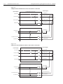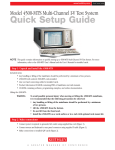
1
4510-QIVC and 4511-QIVC Quad IV Cards User’s Manual A GREATER MEASURE OF CONFIDENCE WARRANTY Keithley Instruments, Inc. warrants this product to be free from defects in material and workmanship for a period of 1 year from date of shipment. Keithley Instruments, Inc. warrants the following items for 90 days from the date of shipment: probes, cables, rechargeable batteries, diskettes, and documentation. During the warranty period, we will, at our option, either repair or replace any product that proves to be defective. To exercise this warranty, write or call your local Keithley representative, or contact Keithley headquarters in Cleveland, Ohio. You will be given prompt assistance and return instructions. Send the product, transportation prepaid, to the indicated service facility. Repairs will be made and the product returned, transportation prepaid. Repaired or replaced products are warranted for the balance of the original warranty period, or at least 90 days. LIMITATION OF WARRANTY This warranty does not apply to defects resulting from product modification without Keithley’s express written consent, or misuse of any product or part. This warranty also does not apply to fuses, software, non-rechargeable batteries, damage from battery leakage, or problems arising from normal wear or failure to follow instructions. THIS WARRANTY IS IN LIEU OF ALL OTHER WARRANTIES, EXPRESSED OR IMPLIED, INCLUDING ANY IMPLIED WARRANTY OF MERCHANTABILITY OR FITNESS FOR A PARTICULAR USE. THE REMEDIES PROVIDED HEREIN ARE BUYER’S SOLE AND EXCLUSIVE REMEDIES. NEITHER KEITHLEY INSTRUMENTS, INC. NOR ANY OF ITS EMPLOYEES SHALL BE LIABLE FOR ANY DIRECT, INDIRECT, SPECIAL, INCIDENTAL OR CONSEQUENTIAL DAMAGES ARISING OUT OF THE USE OF ITS INSTRUMENTS AND SOFTWARE EVEN IF KEITHLEY INSTRUMENTS, INC., HAS BEEN ADVISED IN ADVANCE OF THE POSSIBILITY OF SUCH DAMAGES. SUCH EXCLUDED DAMAGES SHALL INCLUDE, BUT ARE NOT LIMITED TO: COSTS OF REMOVAL AND INSTALLATION, LOSSES SUSTAINED AS THE RESULT OF INJURY TO ANY PERSON, OR DAMAGE TO PROPERTY. A G R E A T E R M E A S U R E O F C O N F I D E N C E Keithley Instruments, Inc. Corporate Headquarters • 28775 Aurora Road • Cleveland, Ohio 44139 • 440-248-0400 • Fax: 440-248-6168 • 1-888-KEITHLEY (534-8453) • www.keithley.com Belgium: Sint-Pieters-Leeuw • 02-363 00 40 • Fax: 02-363 00 64 • www.keithley.nl Italy: Milano • 02-48 39 16 01 • Fax: 02- 48 39 16 28 • www.keithley.it China: Beijing • 8610-82251886 • Fax: 8610-82251892 • www.keithley.com.cn Japan: Tokyo • 81-3-5733-7555 • Fax: 81-3-5733-7556 • www.keithley.jp Finland: Helsinki • 09-5306-6560 • Fax: 09-5306-6565 • www.keithley.com Korea: Seoul • 82-2-574-7778 • Fax: 82-2-574-7838 • www.keithley.com France: Saint-Aubin • 01-64 53 20 20 • Fax: 01-60 11 77 26 • www.keithley.fr Netherlands: Gorinchem • 0183-635333 • Fax: 0183-630821 • www.keithley.nl Germany: Germering • 089/84 93 07-40 • Fax: 089/84 93 07-34 • www.keithley.de Singapore: Singapore • 65-6747-9077 • Fax: 65-6747-2991 • www.keithley.com Great Britain: Theale • 0118 929 7500 • Fax: 0118 929 7519 • www.keithley.co.uk Sweden: Solna • 08-509 04 600 • Fax: 08-655 26 10 • www.keithley.com India: Bangalore • 080 212 8027 • Fax: 080 212 8005 • www.keithley.com Taiwan: Hsinchu • 886-3-572-9077 • Fax: 886-3-572-9031 • www.keithley.com.tw 2/04 4510-QIVC and 4511-QIVC Quad IV Cards User’s Manual Microsoft® Windows, Microsoft® Excel, and Visual Basic® are either registered trademarks or trademarks of Microsoft® Corporation in the United States and/or other countries. LabView®, LabWindows® are registered trademarks ©2003, Keithley Instruments, Inc. All rights reserved. Cleveland, Ohio, U.S.A. First Printing, December 2003 Document Number: 451XQIVC-900-01 Rev. A Manual Print History The print history shown below lists the printing dates of all Revisions and Addenda created for this manual. The Revision Level letter increases alphabetically as the manual undergoes subsequent updates. Addenda, which are released between Revisions, contain important change information that the user should incorporate immediately into the manual. Addenda are numbered sequentially. When a new Revision is created, all Addenda associated with the previous Revision of the manual are incorporated into the new Revision of the manual. Each new Revision includes a revised copy of this print history page. Revision A (Document Number 451XQIVC-900-01).................................................................... December 2003 All Keithley product names are trademarks or registered trademarks of Keithley Instruments, Inc. Other brand and product names are trademarks or registered trademarks of their respective holders. Safety Precautions The following safety precautions should be observed before using this product and any associated instrumentation. Although some instruments and accessories would normally be used with non-hazardous voltages, there are situations where hazardous conditions may be present. This product is intended for use by qualified personnel who recognize shock hazards and are familiar with the safety precautions required to avoid possible injury. Read and follow all installation, operation, and maintenance information carefully before using the product. Refer to the manual for complete product specifications. If the product is used in a manner not specified, the protection provided by the product may be impaired. The types of product users are: Responsible body is the individual or group responsible for the use and maintenance of equipment, for ensuring that the equipment is operated within its specifications and operating limits, and for ensuring that operators are adequately trained. Operators use the product for its intended function. They must be trained in electrical safety procedures and proper use of the instrument. They must be protected from electric shock and contact with hazardous live circuits. Maintenance personnel perform routine procedures on the product to keep it operating properly, for example, setting the line voltage or replacing consumable materials. Maintenance procedures are described in the manual. The procedures explicitly state if the operator may perform them. Otherwise, they should be performed only by service personnel. Service personnel are trained to work on live circuits, and perform safe installations and repairs of products. Only properly trained service personnel may perform installation and service procedures. Keithley products are designed for use with electrical signals that are rated Measurement Category I and Measurement Category II, as described in the International Electrotechnical Commission (IEC) Standard IEC 60664. Most measurement, control, and data I/O signals are Measurement Category I and must not be directly connected to mains voltage or to voltage sources with high transient overvoltages. Measurement Category II connections require protection for high transient over-voltages often associated with local AC mains connections. Assume all measurement, control, and data I/O connections are for connection to Category I sources unless otherwise marked or described in the Manual. Exercise extreme caution when a shock hazard is present. Lethal voltage may be present on cable connector jacks or test fixtures. The American National Standards Institute (ANSI) states that a shock hazard exists when voltage levels greater than 30V RMS, 42.4V peak, or 60VDC are present. A good safety practice is to expect that hazardous voltage is present in any unknown circuit before measuring. Operators of this product must be protected from electric shock at all times. The responsible body must ensure that operators are prevented access and/or insulated from every connection point. In some cases, connections must be exposed to potential human contact. Product operators in these circumstances must be trained to protect themselves from the risk of electric shock. If the circuit is capable of operating at or above 1000 volts, no conductive part of the circuit may be exposed. Do not connect switching cards directly to unlimited power circuits. They are intended to be used with impedance limited sources. NEVER connect switching cards directly to AC mains. When connecting sources to switching cards, install protective devices to limit fault current and voltage to the card. Before operating an instrument, make sure the line cord is connected to a properly grounded power receptacle. Inspect the connecting cables, test leads, and jumpers for possible wear, cracks, or breaks before each use. When installing equipment where access to the main power cord is restricted, such as rack mounting, a separate main input power disconnect device must be provided, in close proximity to the equipment and within easy reach of the operator. For maximum safety, do not touch the product, test cables, or any other instruments while power is applied to the circuit under test. ALWAYS remove power from the entire test system and discharge any capacitors before: connecting or disconnecting cables or jumpers, installing or removing switching cards, or making internal changes, such as installing or removing jumpers. Do not touch any object that could provide a current path to the common side of the circuit under test or power line (earth) ground. Always make measurements with dry hands while standing on a dry, insulated surface capable of withstanding the voltage being measured. The instrument and accessories must be used in accordance with its specifications and operating instructions or the safety of the equipment may be impaired. Do not exceed the maximum signal levels of the instruments and accessories, as defined in the specifications and operating information, and as shown on the instrument or test fixture panels, or switching card. When fuses are used in a product, replace with same type and rating for continued protection against fire hazard. Chassis connections must only be used as shield connections for measuring circuits, NOT as safety earth ground connections. If you are using a test fixture, keep the lid closed while power is applied to the device under test. Safe operation requires the use of a lid interlock. 5/03 If a screw is present, connect it to safety earth ground using the wire recommended in the user documentation. The ! symbol on an instrument indicates that the user should refer to the operating instructions located in the manual. The symbol on an instrument shows that it can source or measure 1000 volts or more, including the combined effect of normal and common mode voltages. Use standard safety precautions to avoid personal contact with these voltages. The frame. symbol indicates a connection terminal to the equipment The WARNING heading in a manual explains dangers that might result in personal injury or death. Always read the associated information very carefully before performing the indicated procedure. The CAUTION heading in a manual explains hazards that could damage the instrument. Such damage may invalidate the warranty. Instrumentation and accessories shall not be connected to humans. Before performing any maintenance, disconnect the line cord and all test cables. To maintain protection from electric shock and fire, replacement components in mains circuits, including the power transformer, test leads, and input jacks, must be purchased from Keithley Instruments. Standard fuses, with applicable national safety approvals, may be used if the rating and type are the same. Other components that are not safety related may be purchased from other suppliers as long as they are equivalent to the original component. (Note that selected parts should be purchased only through Keithley Instruments to maintain accuracy and functionality of the product.) If you are unsure about the applicability of a replacement component, call a Keithley Instruments office for information. To clean an instrument, use a damp cloth or mild, water based cleaner. Clean the exterior of the instrument only. Do not apply cleaner directly to the instrument or allow liquids to enter or spill on the instrument. Products that consist of a circuit board with no case or chassis (e.g., data acquisition board for installation into a computer) should never require cleaning if handled according to instructions. If the board becomes contaminated and operation is affected, the board should be returned to the factory for proper cleaning/servicing. Table of Contents 1 Getting Started Introduction ........................................................................................................................................................ General information ........................................................................................................................................... Features ...................................................................................................................................................... Intended applications ................................................................................................................................. Supported operating system ....................................................................................................................... Supported software platforms .................................................................................................................... Supplied software ....................................................................................................................................... Specifications ............................................................................................................................................. Warranty information ................................................................................................................................. Contact information ................................................................................................................................... Safety symbols and terms .......................................................................................................................... Unpacking and Inspection .......................................................................................................................... Optional accessories ........................................................................................................................................... Card configuration ............................................................................................................................................. Card side view ............................................................................................................................................ Card edge view ........................................................................................................................................... 2 1-2 1-2 1-2 1-3 1-3 1-3 1-3 1-3 1-3 1-4 1-4 1-4 1-7 1-7 1-7 1-9 Installation & Connections Introduction ........................................................................................................................................................ 2-2 Connection precautions ...................................................................................................................................... 2-2 Card installation ................................................................................................................................................. 2-2 Cover removal ............................................................................................................................................ 2-2 Installation procedure ................................................................................................................................. 2-3 Card removal .............................................................................................................................................. 2-5 Card configuration ..................................................................................................................................... 2-5 Software installation .......................................................................................................................................... 2-5 Connections ........................................................................................................................................................ 2-6 Connector terminal designations ................................................................................................................ 2-6 Block diagram ............................................................................................................................................ 2-7 DUT connections ....................................................................................................................................... 2-7 Output states ............................................................................................................................................... 2-8 Reverse current bias and laser diode considerations ................................................................................ 2-11 Using both I-Source and V-Source subchannels with a single DUT ....................................................... 2-11 Interlock ........................................................................................................................................................... 2-13 Interlock events ........................................................................................................................................ 2-13 Interlock connections ............................................................................................................................... 2-13 Interlock connector and cables ................................................................................................................. 2-14 Interlock terminal designations ................................................................................................................ 2-15 Multiple card interlock connections ......................................................................................................... 2-16 i 3 Basic Operation Introduction ........................................................................................................................................................ 3-2 Environmental conditions ................................................................................................................................... 3-2 Temperature and humidity ......................................................................................................................... 3-2 Warm-up period .......................................................................................................................................... 3-2 Basic software operation .................................................................................................................................... 3-2 4500-MTS folder ........................................................................................................................................ 3-2 Enabling the emulation mode ..................................................................................................................... 3-3 Using the Embedded Sweep Example program ................................................................................................. 3-4 Overview .................................................................................................................................................... 3-4 Running the 4500-MTS Embedded Sweep Example program .................................................................. 3-5 Connecting to the 4500-MTS ..................................................................................................................... 3-6 Building a new channel group .................................................................................................................... 3-7 Removing a channel from a channel group ................................................................................................ 3-9 Configuring a channel ................................................................................................................................ 3-9 Running a test ........................................................................................................................................... 3-14 Saving test data to a file ............................................................................................................................ 3-15 4 Programming Introduction ........................................................................................................................................................ 4-2 Operation overview ............................................................................................................................................ 4-2 Channel designation description ................................................................................................................. 4-2 Channel groups ........................................................................................................................................... 4-3 Sweep and sourcing terminology ............................................................................................................... 4-4 Immediate mode ......................................................................................................................................... 4-7 Memory capacity ........................................................................................................................................ 4-8 Using the 4500 driver with various programming environments ..................................................................... 4-10 References to online help ......................................................................................................................... 4-10 Basic assumptions .................................................................................................................................... 4-10 Using specific programming environments .............................................................................................. 4-10 User programming ............................................................................................................................................ 4-12 Remote mode ............................................................................................................................................ 4-12 Driver details ............................................................................................................................................ 4-12 Source code .............................................................................................................................................. 4-13 Driver functions ........................................................................................................................................ 4-13 A Specifications B Terms, Concepts, and Definitions Introduction ....................................................................................................................................................... B-2 C Output Control Relay Lifetime Output control relay ........................................................................................................................................... C-2 Lifetime rating ................................................................................................................................................... C-2 ii List of Illustrations 1 Getting Started Figure 1-1 Figure 1-2 Figure 1-3 Figure 1-4 Figure 1-5 Figure 1-6 Figure 1-7 QIVC cable (4500-CQIV-2) ...................................................................................................................... QIVC Interlock Cable (4500-CILK-2) ...................................................................................................... 15 pin D-sub female solder-cup connector (4500-CIV-KIT-1) ................................................................. QIVC Test Lead Set (Model 4500-QIVC-TLS) ........................................................................................ Interlock override plug (4500-ILK-PLUG) ............................................................................................... 451x-QIVC card side view ........................................................................................................................ 451x-QIVC card edge view ....................................................................................................................... 2 Installation & Connections Figure 2-1 Figure 2-2 Figure 2-3 Figure 2-4 Figure 2-5 Figure 2-6 Figure 2-7 Figure 2-8 Figure 2-9 Figure 2-10 Figure 2-11 Figure 2-12 Figure 2-13 Case cover removal .................................................................................................................................... 2-4 Flat plate removal ....................................................................................................................................... 2-4 Card installation ......................................................................................................................................... 2-5 Card block diagram .................................................................................................................................... 2-7 DUT connections ....................................................................................................................................... 2-8 Output On state ........................................................................................................................................ 2-10 Output Off_Shorted state ......................................................................................................................... 2-10 Output Off_Open state ............................................................................................................................. 2-11 LED forward bias simultaneous I-Source and V-Source connections ..................................................... 2-12 LED reverse bias simultaneous I-Source and V-Source connections ...................................................... 2-12 Connections directly to card interlock connector .................................................................................... 2-14 Connections to interlock cable 9-pin connector ....................................................................................... 2-15 Multiple card interlock connections ......................................................................................................... 2-17 3 Basic Operation Figure 3-1 Figure 3-2 Figure 3-3 Figure 3-4 Figure 3-5 Figure 3-6 Figure 3-7 Figure 3-8 Figure 3-9 Figure 3-10 Figure 3-11 Figure 3-12 Typical 4500-MTS folder contents ............................................................................................................ 3-3 4500-MTS control panel System Settings tab ............................................................................................ 3-4 Running VB Embedded Sweep Example program using Start menu ........................................................ 3-5 Embedded sweep example program initial window .................................................................................. 3-6 Typical card configuration window ........................................................................................................... 3-7 Typical channel group configuration window ........................................................................................... 3-8 Group configuration window after group creation .................................................................................... 3-8 Typical card properties window ................................................................................................................. 3-9 I Linear Sweep settings ............................................................................................................................ 3-11 I-Bias settings ........................................................................................................................................... 3-12 I-List Sweep settings ................................................................................................................................ 3-12 Typical Sweep Results ............................................................................................................................. 3-15 1-5 1-5 1-5 1-6 1-6 1-8 1-9 iii 4 Programming Figure 4-1 Figure 4-2 Figure 4-3 Figure 4-4 Figure 4-5 Figure 4-6 Subchannel block diagram ......................................................................................................................... 4-2 Channel designation example ..................................................................................................................... 4-3 Current source output during sweep ........................................................................................................... 4-4 Block diagram example of a Linear Sweep ................................................................................................ 4-5 Block diagram of an Immediate Mode test ................................................................................................ 4-7 Remote Mode connection block diagram ................................................................................................. 4-12 B Terms, Concepts, and Definitions Figure B-1 Figure B-2 Figure B-3 RTM System Tray Icon ............................................................................................................................. B-2 Four channel nested sweep example ......................................................................................................... B-4 Four channel parallel sweep example ........................................................................................................ B-5 iv List of Tables 2 Installation & Connections Table 2-1 Table 2-2 Table 2-3 Connector terminal designations (each channel) ....................................................................................... 2-6 Output states for KE4500_EnableOutputs() command ............................................................................. 2-9 Interlock connector and cable terminal designations ............................................................................... 2-15 3 Basic Operation Table 3-1 Valid current source and voltage source output states ............................................................................. 3-10 B Terms, Concepts, and Definitions Table B-1 Table B-2 Subchannel measure capabilities .............................................................................................................. B-7 Subchannel source capabilities ................................................................................................................. B-7 v 1 Getting Started 1-2 Getting Started 4510-QIVC and 4511-QIVC Quad IV Cards User’s Manual Introduction This user’s manual describes operation of the 4510-QIVC and 4511-QIVC Quad IV cards. After reading this document, you should be able to perform the following tasks: • • • • • Open up the mainframe. Plug a card into the mainframe. Connect the hardware necessary to operate a card with the mainframe. Use the Keithley 4510-QIVC and 4511-QIVC Embedded Sweep Example program. Perform basic programming tasks to control and take measurements with the card using the supplied library of driver calls. General information Features The 4510-QIVC and 4511-QIVC cards are intended to provide parallel real-time source/measure capability in a cost-effective, compact, and scalable platform. These applications typically take two forms: multi-channel I-V test or multi-channel intelligent power supply. Applications requiring multi-channel I-V capability include on wafer test of LEDs, VCSELs, and Optoelectronic ICs where a large number of channels need to perform I-V sweeps in parallel or in coordination with each other. Applications that require multi-channel intelligent power supply capability include accelerated life test and functional device test that require large numbers of channels to sourcing currents or voltages while monitoring power consumption. The 4510-QIVC provides three current source ranges: 30mA, 100mA, and 500mA, at up to 6V compliance. The 4511-QIVC is a higher current unit also providing three source current ranges at 100mA, 300mA, and 1A without compromising instrument specifications or functionality. Both cards also have a programmable ±10V voltage source with source read-back and precision three-range (10µA, 500µA, 10mA) current measurement. Together these cards provide coverage for a wide variety of source/measure applications. The following list summarizes the major features of 4510-QIVC and 4511-QIVC: • • • • • Channel Density — The channel density provided by the 4510-QIVC and 4511-QIVC allows for testing of up to 36 channels in a single 4500-MTS chassis. Channel density allows you to perform massively parallel tests to accelerate throughput. Source/Measure Combinations — The 4510-QIVC and 4511-QIVC plug-in cards offer modular precision source-measure capability. Each card provides four channels, and each channel includes a current source subchannel and a voltage source subchannel. Each channel also includes an instrument grade A/D converter for highest possible throughput without compromising precision. Integrated Test System — The internal PC and Windows® 2000 Operating System of the 4500 system allow users to eliminate the test system controller from new test stands. With ethernet interface capability, the 4500-MTS can interface directly with facility databases for transfer of test data. User Safety — The 4510-QIVC and 4511-QIVC provide for user safety (electrical and optical) for the target component types. Voltage source capability will not exceed 48V on any circuit. The system also provides for software and hardware abort capability upon interlock. High Test Throughput and Accuracy — The 4510-QIVC and 4511-QIVC provide fast and accurate measurements. 4510-QIVC and 4511-QIVC Quad IV Cards User’s Manual • • Getting Started 1-3 User Interface — The 4500 comes with standard drivers for the LabView, LabWindows/CVI, Visual C/C++, and Visual Basic® programming environments. In addition, application demo programs in LabView, LabWindows/CVI, and Visual Basic® are provided to supplement the development of test programs. Sweep and Immediate Data Measurement Retrieval — The 4510-QIVC and 4511-QIVC cards provide sweep capability along with immediate data measurement retrieval. Intended applications The 4510-QIVC and 4511-QIVC cards are designed for multi-channel I-V test and multi-channel intelligent power supply applications where source requirements are limited to 1A or 10V per channel. Supported operating system The 451x-QIVC driver software is compatible with the following operating system: • Windows® 2000 Workstation (required for 4500-MTS) Supported software platforms The 451x-QIVC drivers are compatible with the following test software platforms: • • • • MS Visual Basic® Version 5 and 6 MS Visual C/C++ (32 bit) NI LabView Version 5.1 and higher NI LabWindows/CVI Version 5.5 and higher Supplied software The following software is supplied with the 451x-QIVC cards: • • • Win32 DLL driver for the card that supports the above software platforms. Embedded Sweep Example Software that demonstrates card sweep capabilities and allows you to perform simple tests. Example application programs. Specifications Detailed specifications are located in Appendix A. For the latest specifications, check www.keithley.com. Warranty information Warranty information is located at the front of this manual. Should your Model 4510-QIVC or 4511-QIVC require warranty service, contact the Keithley representative or authorized repair facility in your area for further information. When returning the instrument for repair, be sure to fill out and include the service form at the back of this manual to provide the repair facility with the necessary information. 1-4 Getting Started 4510-QIVC and 4511-QIVC Quad IV Cards User’s Manual Contact information Worldwide phone numbers are listed at the front of this manual. If you have any questions, please contact your local Keithley representative or call one of our Application Engineers at 1-800-348-3735 (U.S. and Canada only). Safety symbols and terms If a screw is present, connect it to safety earth ground using the wire recommended in the user documentation. The ! symbol on an instrument indicates that the user should refer to the operating instructions located in the manual. The symbol on an instrument shows that it can source or measure 1000 volts or more, including the combined effect of normal and common mode voltages. Use standard safety precautions to avoid personal contact with these voltages. The symbol indicates a connection terminal to the equipment frame. The WARNING heading in a manual explains dangers that might result in personal injury or death. Always read the associated information very carefully before performing the indicated procedure. The CAUTION heading in a manual explains hazards that could damage the instrument. Such damage may invalidate the warranty. . Unpacking and Inspection Inspection for damage The Model 451x-QIVC card was carefully inspected electrically and mechanically before shipment. After unpacking all items from the shipping carton, check for any obvious signs of physical damage that may have occurred during transit. Report any damage to the shipping agent immediately. Save the original packing carton for possible future shipment. Package content The following items are included with every Model 451x-QIVC card order: • • • • • • • Model 4510-QIVC Low Power Quad I/V Card or 4511-QIVC High Power Quad I/V card. QIVC Cable (4500-CQIV-2) signal connecting cable (2m) with MDR connectors for QIVC to 4 male 15 pin D-sub connectors (Figure 1-1). QIVC Interlock Cable (4500-CILK-2) cable (2m) with MDR connector to male 9 pin D-Sub (Figure 1-2). 15 pin D-sub female solder-cup connector (4500-CIV-KIT-1, Qty: 4). Mates to 4500-CQIV-*, provided for DUT connection (Figure 1-3). QIVC Test Lead Set (Model 4500-QIVC-TLS), 15 pin D-sub to 8 alligator clips, provided. for temporary DUT connection and troubleshooting (Figure 1-4). Interlock override plug (4500-ILK-PLUG). 9 pin D-sub mates to 4500-CILK-* interlock cable, overrides the interlock functionality on all four channels (Figure 1-5). Additional accessories as ordered. 4510-QIVC and 4511-QIVC Quad IV Cards User’s Manual Figure 1-1 QIVC cable (4500-CQIV-2) Figure 1-2 QIVC Interlock Cable (4500-CILK-2) Figure 1-3 15 pin D-sub female solder-cup connector (4500-CIV-KIT-1) Getting Started 1-5 1-6 Getting Started 4510-QIVC and 4511-QIVC Quad IV Cards User’s Manual Figure 1-4 QIVC Test Lead Set (Model 4500-QIVC-TLS) Figure 1-5 Interlock override plug (4500-ILK-PLUG) 4510-QIVC and 4511-QIVC Quad IV Cards User’s Manual Getting Started 1-7 Optional accessories For more information on optional accessories, refer to www.keithley.com. The following cables are available: • 4500-CQIV-* — This cable has a 40-pin connector that mates with the 451x-QIVC card signal connector on one end and a 15-pin D-Sub connector for each of the four channels on the other end. NOTE • 4500-CILK-* — This cable has a 14-pin male connector that mates with the 451x-QIVC card interlock on one end and a 9-pin D-Sub female connector at the other end. NOTE • • • This cable is available in 0.5, 1, 2, and 3 meters. 0.5 to 2 meter lengths are recommended for use with the 4511-QIVC. 3 meter length is recommended for use only with the 4510-QIVC. This cable is available in 0.5, 1, 2, and 3 meters. 4500-ILK-KIT-1 — This kit contains a mating connector and housing for interlock wiring. The connector mates to the 451x-QIVC card interlock connector for a single card. 4500-CIV-KIT-1 — This kit contains a mating connector for wiring. This kit is for use with the 4500-CQIV-*. 4500-QIVC-TLS — This test lead set adapts the 15 pin D-sub, for a single channel, to eight alligator clips. It provides a quick method for initial DUT connections. Card configuration Card side view Figure 1-6 shows the 451x-QIVC card side view. Key components include: • • • • DUT signal connector — provides connections to the DUTs using the supplied connecting cable (see “Connections,” page 2-6). Interlock connector — connects to a test fixture interlock (see “Interlock,” page 2-13). Edge connectors — connects the card to the PCI bus, analog power bus, and trigger bus of the mainframe (see Section 2 of the 4500-MTS Mainframe User’s Manual). Heat sink — cools power output stages of card. WARNING The heat sink may be hot after extended operation at higher power levels. Do not touch the heat sink or adjacent power components until the card has cooled sufficiently. 1-8 Getting Started 4510-QIVC and 4511-QIVC Quad IV Cards User’s Manual Figure 1-6 451x-QIVC card side view Heat sink DUT signal connector Interlock connector Edge connectors 4510-QIVC and 4511-QIVC Quad IV Cards User’s Manual Getting Started 1-9 Card edge view Figure 1-7 shows the edge view of the card. Key components include: • • • DUT connector — provides signal connections for all four channels to the DUTs using the supplied connecting cable (see Section 2). INTLK (interlock) connector — provides connections to a test fixture interlock for safety purposes (see Section 2). Rear mounting plate — secures card to rear panel of mainframe (see Section 2). Figure 1-7 451x-QIVC card edge view KEITHLEY 4510 QIVC DUT Signal Connector DUT Interlock Connector INTLK Rear Mounting Plate 2 Installation & Connections 2-2 Installation & Connections 4510-QIVC and 4511-QIVC Quad IV Cards User’s Manual Introduction This section includes information on card installation, software installation, and connecting DUTs (Device Under Test) to the card. Connection precautions WARNING Read all safety precautions listed at the beginning of this manual. The following safety practices must be used to protect operators and other users of this product from potential exposure to electrical hazards: • Operators must be protected from electrical hazards at all times. • The interlock is required for safe operation. The test fixtures must ensure that the interlock circuit is disabled (source outputs inhibited) so that an operator is not exposed to any harmful conditions. See “Interlock,” page 2-13 for interlock information. • Maximum isolation from earth ground is ±20V. Exceeding this value may result in a shock hazard. • When making connections, do not leave any exposed connections. Be sure that all external circuits are properly insulated. Card installation WARNING The following information is intended only for qualified service personnel. Do not attempt these procedures unless you are qualified to do so. Some of these procedures may subject you to electric shock, possibly causing personal injury or death. NOTE The 4500-MTS mainframe is shipped from the factory with ordered measurement cards already installed. The following procedure is intended for those who wish to install additional cards in the field. Cover removal WARNING Disconnect the line cord and all other cables from the mainframe before removing the cover. Tools Required #1 Tip Phillips Screwdriver Wrist ground strap Procedure 1. Remove the six (6) screws that secure the cover to the case (located on the bottom side of chassis (Figure 2-1, page 2-4). 2. Carefully remove the cover from the case by sliding it off the top of the chassis. 3. Loosen the twelve (12) screws that secure the flat cover plate to the chassis (Figure 2-2, page 2-4), slide the plate toward rear of chassis about 0.25" and lift off. 4510-QIVC and 4511-QIVC Quad IV Cards User’s Manual WARNING Installation & Connections 2-3 The safety shield that covers the fan and front area should not be removed for card installation/removal or cover removal, and it should be removed only for servicing. Hazardous voltages will be exposed when the shield is removed. Rotating fan blades can cause minor cuts or injury. Keep hands clear when servicing. 4. To re-install, install the flat cover plate and tighten the twelve (12) screws, place the cover on the case, then attach it with the six (6) screws. Installation procedure Install a 4510-QIVC or 4511-QIVC card using the procedure below and Figure 2-3 on page 2-5 as a guide. This procedure assumes that the case cover is already removed as previously discussed. CAUTION Handle the card only by the edges to avoid contamination that could affect measurement quality. Do not touch PC board traces or edge connector contacts. Use a ground strap and proper grounding techniques to avoid damage caused by static discharge. NOTE A maximum of eight 4511-QIVC cards should be installed in a 4500-MTS mainframe. Operation with nine 4511-QIVC cards is not recommended. 1. Remove the desired slot cover plate from the rear panel by removing the securing screw (1) and bracket. 2. Remove the PCI card retainer by loosening the three (3) retaining screws and sliding the bracket off. 3. Carefully remove the card from its antistatic (shipping) bag. 4. Position the card above the appropriate PCI slot, aligning the card with the card edge rails and rear slot opening. Line up the edge connectors with the slot connectors on the backplane, and then carefully insert the card into those connectors. Make sure the card is properly seated in all connectors by applying firm, even pressure to the top edge of the card. 5. Install the screw (1) at the rear panel location to secure the card. 6. Re-install the PCI card retainer; retighten the three (3) screws. 7. Replace the mainframe top cover plate and cover. 2-4 Installation & Connections 4510-QIVC and 4511-QIVC Quad IV Cards User’s Manual Figure 2-1 Case cover removal Case Cover Slide Cover Off Carefully Remove Six (6) Screws Figure 2-2 Flat plate removal Loosen Twelve (12) Screws Flat Cover Plate Slide Cover Toward Rear of Chassis 0.25”. Lift Flat Cover Plate Off. 4510-QIVC and 4511-QIVC Quad IV Cards User’s Manual Installation & Connections 2-5 Figure 2-3 Card installation 4510-QIVC or 4511-QIVC Card PCI Retainer Bracket Remove Securing Screw and Bracket Reuse Screw to Secure 45XX-QIVC Card Install Card in Desired PCI Slot Loosen Three (3) Screws Card removal To remove a card, first disconnect all cables connected to the card, remove the rear plate screw, and then remove the card from the slot. Card configuration The operating system software will automatically recognize and configure the card the next time the mainframe power is turned on. Card operation is covered in Section 3. Software installation NOTE 1. 2. 3. 4. 5. The software will be already installed on the 4500-MTS hard drive. The procedure below should be used to re-install or upgrade software. Install CD. Setup.exe should run automatically. Accept all of the installation defaults. Reboot the 4500-MTS and login. Exit (close) the 4500-MTS Real-Time Manager. Upgrade the QIVC firmware through the Control Panel applet labeled 4500-MTS. In Start->Settings->Control Panel, double-click the 4500-MTS icon, and select the Flash Upgrade tab. After pressing the Start Flash Upgrade button, navigate to the C:\Program Files\Keithley Instruments\4500-MTS\bin\QIVC Flash Upgrade folder and select the file named 4510-QIVC-*.fx for the 4510-QIVC, or 4511-QIVC-*.fx for the 4511-QIVC. Select Open. After a few seconds, the applet should signal completion with a series of three beeps and a status message. 2-6 Installation & Connections 4510-QIVC and 4511-QIVC Quad IV Cards User’s Manual 6. Upgrade the Digital FPGA image. Repeat step 5 using the *.dx file type selector and the file named 45xx-QIVC-*.dx in the same directory. 7. Upgrade the Analog FPGA image. Repeat step 5 using the *.ax file type selector and the file named 45xx-QIVC-*.ax in the same directory. 8. Start the 4500-MTS Real-Time Manager located in the 4500-MTS folder. 9. Run the VB Embedded Sweep Example program located in the 4500-MTS folder. 10. Click Connect, and confirm the digital FPGA, analog FPGA, and firmware were successfully programmed. Version information is displayed in the Card Identification field. Repeat steps 4 through 7 if incorrect. Connections WARNING The following information is intended only for qualified service personnel. Do not attempt these procedures unless you are qualified to do so. Some of these procedures may subject you to electric shock, possibly causing personal injury or death. Connector terminal designations The supplied 4500-CQIV-2 signal connecting cable is designed to mate with the DUT signal connector on the card. The cable branches out to four connectors on the other end, one for each of the four identical channels, labeled A through D. Table 2-1 lists card connector terminal designations for each of the four channels. Table 2-1 Connector terminal designations (each channel) Signal Connector pin(s) I-SOURCE HI 1 3 and 11 1 V-MEASURE HI 4 V-MEASURE LO1 12 I-SOURCE LO1 V-BIAS HI2 5 and 13 1 GUARD2 2 V-BIAS SENSE LO2 10 V-BIAS LO2 9 1. Current source connections 2. Voltage source connections 4510-QIVC and 4511-QIVC Quad IV Cards User’s Manual Installation & Connections 2-7 Block diagram Figure 2-4 shows a block diagram of one channel of the 451x-QIVC cards. Each of the four channels is identical. Each of the four channels has two subchannels: I-Source and V-Source. In addition to sourcing current, the I-Source subchannel measures the voltage and, optionally, the current (current readback). The current source subchannel is useful for testing many types of DUTs. The current source sections include circuitry for current readback, voltage measurement, and compliance, while the voltage source section has current measurement and voltage readback circuits. Both sections include output relays that control connections to the DUTs. Figure 2-4 Card block diagram Pin 3 & 11 : I-SOURCE HI I-READBACK Output control relays V-MEASURE & V-COMPLIANCE I-SOURCE Pin 4: V-MEASURE HI Pin 12: V-MEASURE LO NOTE: The I-SOURCE circuit is bi-polar. It can source positive or negative current. Pin 5 & 13: I-SOURCE LO QIVC cable pin-out (Channel A-D) High impedance pathways. Negligible current flow. 1 2 3 4 5 6 7 8 9 10 11 12 13 14 15 I-MEASURE Pin 1: V-SOURCE HI X1 V-SOURCE V-READBACK Output control relays Pin 2: GUARD Pin 10: V-SOURCE SENSE LO NOTE: The V-SOURCE circuit is bi-polar. It can source positive or negative voltage. Pin 9: V-SOURCE LO DUT connections Figure 2-5 shows DUT connections. I-SOURCE HI and V-MEASURE HI are connected to the diode anode (DUT A), while I-SOURCE LO and V-MEASURE LO are connected to the diode cathode. V-SOURCE HI is connected to the diode anode (DUT B), while V-SOURCE LO and V-SOURCE SENSE LOW are connected to the diode cathode. GUARD is connected to the shield of the cable connected to V-SOURCE HI to shield the sensitive signal path against interference. The GUARD connection may be required when high quality low current (10µA range) measurements are required. 2-8 Installation & Connections 4510-QIVC and 4511-QIVC Quad IV Cards User’s Manual Figure 2-5 DUT connections I-SOURCE HI I-READBACK V-MEASURE HI Output control relays V-MEASURE & V-COMPLIANCE I-SOURCE DUT A V-MEASURE LO I-SOURCE LO V-SOURCE HI I-MEASURE X1 V-SOURCE V-READBACK GUARD Output control relays DUT B V-SOURCE SENSE LO V-SOURCE LO Output states There is one output On state and two Off states. Figure 2-6 shows the On state compared with the Off_Shorted and Off_Open states in Figure 2-7 and Figure 2-8 respectively. Table 2-2 summarizes the available Output states. NOTE See Section 4 for a description of the KE4500_EnableOutputs() command. Output ON state When the output is turned on (Figure 2-6), the internal terminal shorts (I-Source and V-Source ) are opened, and the I-SOURCE terminals are connected to DUT A and the V-SOURCE terminals are connected to DUT B. Output Off_Shorted state When the output is in the Off_Shorted state (Figure 2-7), the I-SOURCE is disconnected from DUT A, and the DUT terminals are shorted together. DUT B terminals are also shorted together by internally connecting V-SOURCE HI and V-SOURCE LO. 4510-QIVC and 4511-QIVC Quad IV Cards User’s Manual Installation & Connections 2-9 Output Off_Open state As shown in Figure 2-8, the I-Source and V-Source subchannel connections can be completely isolated. Table 2-2 summarizes allowed states for the I-Source and V-Source subchannels. When the output is in the Off_Open state, all source and measure connections are isolated (also referred to as the high impedance off state). Table 2-2 Output states for KE4500_EnableOutputs() command I-Source subchannel V-Source subchannel Off_Shorted1 Off_Shorted1 ON ON ON Off_Shorted1 Off_Shorted1 ON ON Off_Open2 Off_Open2 ON Off_Open2 Off_Open2 1. Off_Shorted: I Source HI and LO leads shorted together and V Source HI and LO leads shorted together. See Figure 2-7. 2. Off_Open: All Source and Measure leads isolated from each other and from QIV cable. This mode may also be referred to as “isolated” or “high-impedance (Hi-Z)”. See Figure 2-8. NOTE Be aware that the Guard pin is not isolated in the OFF_OPEN state. 2-10 Installation & Connections 4510-QIVC and 4511-QIVC Quad IV Cards User’s Manual Figure 2-6 Output On state Internal Signals I-SOURCE Output Control Relays (OUTPUT ON) External Signals I-SOURCE HI I-SOURCE HI V-MEASURE HI V-MEASURE HI DUT A V-MEASURE LO V-MEASURE LO I-SOURCE LO I-SOURCE LO V-SOURCE Output Control Relays (OUTPUT ON) V-SOURCE HI V-SOURCE HI GUARD GUARD DUT B V-SOURCE SENSE LO V-SOURCE SENSE LO V-SOURCE LO V-SOURCE LO Figure 2-7 Output Off_Shorted state Internal Signals External Signals I-SOURCE Output Control Relays (OUTPUT OFF_SHORTED) I-SOURCE HI I-SOURCE HI V-MEASURE HI V-MEASURE HI DUT A V-MEASURE LO V-MEASURE LO I-SOURCE LO I-SOURCE LO V-SOURCE Output Control Relays (OUTPUT OFF_SHORTED) V-SOURCE HI V-SOURCE HI GUARD GUARD DUT B V-SOURCE SENSE LO V-SOURCE SENSE LO V-SOURCE LO V-SOURCE LO 4510-QIVC and 4511-QIVC Quad IV Cards User’s Manual Installation & Connections 2-11 Figure 2-8 Output Off_Open state I-SOURCE Output Control Relays (OUTPUT OFF_OPEN) I-SOURCE HI I-SOURCE HI V-MEASURE HI V-MEASURE HI DUT A V-MEASURE LO V-MEASURE LO I-SOURCE LO I-SOURCE LO V-SOURCE Output Control Relays (OUTPUT OFF_OPEN) V-SOURCE HI V-SOURCE HI GUARD GUARD DUT B V-SOURCE SENSE LO V-SOURCE SENSE LO V-SOURCE LO V-SOURCE LO Reverse current bias and laser diode considerations Some diode-like devices, laser diodes in particular, may tolerate very little reverse current. The QIVC specifications show that there is a small ambiguity of the current source at zero current, which is given as the offset portion of the current source accuracy specification (Appendix A). This offset current is unsigned, meaning it may be a negative, or reverse, current. If this current may cause problems with the device under test, adjust the source value slightly positive by this offset when the desired output current would be normally be set to zero. Using both I-Source and V-Source subchannels with a single DUT The Off_Open state isolates the subchannels individually. By using this subchannel isolation, it is possible to connect both the I-Source and V-Source leads to the same DUT and power the DUT with either subchannel. As an example, for LED testing, both QIV subchannels provide unique capabilities. Figure 2-9 shows forward bias connections, while Figure 2-10 shows reverse bias connections. In Figure 2-9, the I-Source subchannel is used to power the LED for forward voltage and other emission-oriented measurements. In Figure 2-10, the V-Source subchannel is used for reverse voltage leakage measurements. 2-12 Installation & Connections 4510-QIVC and 4511-QIVC Quad IV Cards User’s Manual Figure 2-9 LED forward bias simultaneous I-Source and V-Source connections Internal Signals I-SOURCE Output Control Relays External Signals I-SOURCE HI I-SOURCE HI V-MEASURE HI V-MEASURE HI DUT V-MEASURE LO V-MEASURE LO I-SOURCE LO I-SOURCE LO V-SOURCE Output Control Relays V-SOURCE HI V-SOURCE HI GUARD GUARD V-SOURCE SENSE LO V-SOURCE SENSE LO V-SOURCE LO V-SOURCE LO Figure 2-10 LED reverse bias simultaneous I-Source and V-Source connections Internal Signals I-SOURCE Output Control Relays External Signals I-SOURCE HI I-SOURCE HI V-MEASURE HI V-MEASURE HI DUT V-MEASURE LO V-MEASURE LO I-SOURCE LO I-SOURCE LO V-SOURCE Output Control Relays V-SOURCE HI V-SOURCE HI GUARD GUARD V-SOURCE SENSE LO V-SOURCE SENSE LO V-SOURCE LO V-SOURCE LO 4510-QIVC and 4511-QIVC Quad IV Cards User’s Manual Installation & Connections 2-13 Interlock Each card is equipped with an interlock connector that can be used to inhibit the source outputs of each individual channel when an external switch is open. WARNING The interlock should always be used to protect operators and other users from potential safety hazards. Interlock events When an interlock event occurs: 1. Set I-SOURCE subchannel to 0A and set V-SOURCE subchannel to 0V. 2. The source relay states are changed immediately for that channel’s interlock line, the I-SOURCE is disconnected from the output terminals, and the DUT terminals are shorted together. The V-SOURCE terminals are shorted together by internally connecting V-SOURCE HI and V-SOURCE LO. 3. An interrupt is generated, and the test sequence is halted for the channel group containing that channel, passing the event to the Real-Time Manager. 4. The test cannot be resumed. The test must be re-initiated after the interlock is recovered. Interlock connections Figure 2-11 shows typical connections directly from the 451x-QIVC card interlock connector to an interlock switch in a test fixture. In this instance, a single interlock switch is connected to the enable lines of all four channels. Other applications that require the output of each channel to be individually controlled will require a separate switch for each channel. In either case, outputs will be enabled (turned on) when the switch is closed. When the switch is open, output(s) will be turned off (as described in Step 2 above) and cannot be turned on. See Figures 2-8 through 2-10 for output on and the two output off states. CAUTION Under no circumstances should the interlock lines be intentionally shorted to chassis ground. Improper operation will result. The interlock is not designed to protect the DUT during an interlock event. In the interest of protecting the operator, the output relays of the interlock circuit close immediately and before the output is driven to a low voltage potential. As a result, the DUT will see the energy in the DUT cable. This energy may display as a significant negative (opposite polarity of the source current) voltage at the DUT. Activating the interlock may damage the DUT. NOTE The +5V line on the interlock connector (pin 1) is internally protected with a 0.75A fuse. Inadvertently shorting this line to chassis ground will trip the fuse, disabling the interlock control circuits, and outputs cannot be turned on. The fuse will automatically reset a few minutes after the overload condition is removed. 2-14 Installation & Connections 4510-QIVC and 4511-QIVC Quad IV Cards User’s Manual Figure 2-11 Connections directly to card interlock connector 4510-QIVC or 4511-QIVC Card Pin 1 +5V Pin 4 Channel A Enable Card interlock connector terminals Switch Test fixture Pin 5 Channel B Enable Pin 6 Channel C Enable Channel D Enable Pin 7 Channel outputs are enabled when switch is closed, disabled when switch is open. Interlock connector and cables To facilitate interlock connections, the following connector and cable kit are available: • • Mating connector for rear panel interlock connector — Keithley model number 4500-ILK-KIT-1 Interlock cable kit — Keithley model # 4500-CILK-*, where * relates to available cable lengths (0.5, 1, 2, 3 meters). See Figure 2-12 for connections to the 9-pin connector on the end of this cable. 4510-QIVC and 4511-QIVC Quad IV Cards User’s Manual Installation & Connections 2-15 Figure 2-12 Connections to interlock cable 9-pin connector Card interlock connector terminals 4510-QIVC or 4511-QIVC Card Interlock cable 9-pin connector terminals Pin 1 +5V Pin 1 Channel A Enable Channel B Enable Channel C Enable Channel D Enable Pin 4 Pin 7 Pin 5 Pin 3 Pin 6 Pin 8 Pin 7 Pin 4 Switch Test fixture Channel outputs are enabled when switch is closed, disabled when switch is open. 4500-CILK-* interlock cable Interlock terminal designations Table 2-3 summarizes terminal designations for the 14-pin interlock connector on the 451x-QIVC and the 9-pin connector on the interlock cable. Table 2-3 Interlock connector and cable terminal designations 14-pin interlock connector 9-pin cable connector 1 1 +5VD (+5V digital supply) 2 6 DIAG – RX (not implemented) 3 2 DIAG – TX (not implemented) 4 7 Interlock Channel A Enable 5 3 Interlock Channel B Enable 6 8 Interlock Channel C Enable 7 4 Interlock Channel D Enable 8 9 D – GND (digital ground) 9 – 14 N.C. Signal description —— 2-16 Installation & Connections 4510-QIVC and 4511-QIVC Quad IV Cards User’s Manual Multiple card interlock connections When channel groups span cards, interlocks may be tied together across cards. For more than four channels, use a separate +5V fused line (pin 1) for every four channel interlock enable lines. An example of multiple card interlock connections is shown in Figure 2-13. This example has two channel groups: • • Group 1— Card 1 Channel A, Card 1 Channel B, Card 1 Channel C. Group 2 — Card 1 Channel D, Card 2 Channel A, Card 2 Channel B. 4510-QIVC and 4511-QIVC Quad IV Cards User’s Manual Installation & Connections 2-17 Figure 2-13 Multiple card interlock connections Card interlock connector terminals 451x-QIVC Card #1 +5V Interlock cable 9-pin connector terminals Pin 1 Pin 1 Channel A Enable Channel B Enable Channel C Enable Channel D Enable Pin 4 Pin 7 Pin 5 Pin 3 Pin 6 Pin 8 Pin 7 Pin 4 Test fixture #1 Closing switch enables Card 1 Channels A, B, and C. 4500-CILK-* interlock cable Card interlock connector terminals 451x-QIVC Card #2 +5V Switch Pin 1 Pin 1 Channel A Enable Channel B Enable Channel C Enable Channel D Enable Pin 4 Pin 7 Pin 5 Pin 3 Pin 6 Pin 8 Pin 7 Pin 4 4500-CILK-* interlock cable Interlock cable 9-pin connector terminals Switch Test fixture #2 Closing switch enables Card 1, Channel D, Card 2, Channels A and B. 3 Basic Operation 3-2 Basic Operation 4510-QIVC and 4511-QIVC Quad IV Cards User’s Manual Introduction This section contains basic information for using the 4510-QIVC and 4511-QIVC Quad IV cards, including environmental conditions, and basic software operation when using the embedded sweep example program. NOTE See Appendix B for detailed terms, concepts, and definitions. Environmental conditions Temperature and humidity For optimum accuracy, the 4510-QIVC and 4511-QIVC cards should be operated at an ambient temperature of 18°C to 28°C at a relative humidity of 5% to 60%. For operating environments outside these ranges, accuracy specifications must be derated (see specifications). Warm-up period For optimum accuracy, turn the system on and allow a one-hour warm-up period before use. Basic software operation 4500-MTS folder Figure 3-1 shows the typical contents of the 4500-MTS folder located on the main desktop. NOTE Actual 4500-MTS folder contents may vary, depending on installed cards and software version. Be sure to refer to the release notes and help files for updated software information not contained in this manual. Briefly, contents include: • • • • • Release notes — Includes information on this particular version of 4500-MTS software. Help files — Contains detailed information for using card driver function calls for the software platforms supported by the 4500-MTS. The C Help File covers using the 4500 software with C-based platforms, while the VB Help File has details for use with Visual Basic®. 4500-MTS Real-Time Manager — The real-time manager, which runs in the background, is launched when the system boots and the user logs in. Note that the real-time manager task will automatically execute when the system boots. The Real-Time Manager must be running to access and control the QIV cards. Reset 4500 — Resets the chosen QIV card(s) to power-on conditions. VB Embedded Sweep Example — A Visual Basic® application that demonstrates embedded sweep capabilities. 4510-QIVC and 4511-QIVC Quad IV Cards User’s Manual Basic Operation 3-3 Figure 3-1 Typical 4500-MTS folder contents Enabling the emulation mode There are two basic operating modes for the 4500-MTS system: emulation mode and real mode. The emulation mode provides pretend cards for running existing 4500 programs or developing new ones. The Real mode (Emulation mode disabled) lets programs control 4500 cards in the system. To select the operating mode, double-click on the 4500-MTS icon in the Windows Control Panel, click on the System Settings tab, and then Enable or Disable the emulation mode as desired. Click OK to select. Figure 3-2 shows the control panel System Settings tab, refer to the 4500-MTS Mainframe User’s Manual for other mainframe settings. NOTE Emulation mode provides basic QIV functionality, but is not a complete emulation of a QIV card. All measurements are simulated, operation and test times are invalid, and there is no interlock functionality (the interlock is always over-ridden). 3-4 Basic Operation 4510-QIVC and 4511-QIVC Quad IV Cards User’s Manual Figure 3-2 4500-MTS control panel System Settings tab Using the Embedded Sweep Example program Overview Example program capabilities The supplied Visual Basic Embedded Sweep Program demonstrates 4510-QIVC and 4511-QIVC sweep capabilities. If the emulation mode is enabled, the embedded sweep example program will operate without any cards in the system. If the emulation mode is disabled (real mode), you can use the example program to control card(s) installed in the mainframe, set source values, perform sweeps, and take measurements. NOTE The included Embedded Sweep Example program provides sweep control of the 4500 with QIV card(s), but is not intended as a comprehensive interface to all of the functionality available in the 4500-MTS system. See Section 4 for details on controlling the 4500-MTS using a programming environment. Multiple channel groups A single instance of the 4500-MTS Embedded Sweep Example program can be used to configure different channel groups. However, it can only run one channel group at a time. Multiple channel groups can only be run sequentially after the previous test has stopped. If you would like to run a simultaneous test on another channel group, run a second instance of the Embedded Sweep Example program, and configure another channel group. Embedded sweep example software overview As shown in Figure 3-4, the 4500-MTS Embedded Sweep Example Software screen contains three areas: the Channel Tree on the left side of the screen showing the Channel Groups, context-sensitive configuration tab(s) on the right side, and a status message area at the bottom. The first action is to make a connection to the 4500-MTS by clicking Connect. After the connection is made, the fields on the right side are populated to show what 4500 cards are present in the system. By clicking on one of the channel groups in the tree and clicking on the Configuration tab on the right side, you can see which channels are available (Figure 3-6). By selecting one of the unused channels and clicking on Add to Group, you can start to build a new channel group. 4510-QIVC and 4511-QIVC Quad IV Cards User’s Manual Basic Operation 3-5 Clicking Apply creates the Channel Group, and the tree shows the new channel group and the channels in the group (Figure 3-7). You can configure channels by selecting them in the tree. The tab control will show an appropriate dialog to configure the type of channel you select. Figure 3-8 shows a typical card properties window. By selecting one of the channel groups in the tree, you can run a test and retrieve data into a grid control (Figure 3-12). You can save this data to a file for future analysis. Running the 4500-MTS Embedded Sweep Example program To run the 4500-MTS Embedded Sweep Example program, perform the following steps. 1. To run the example program using the emulation mode, click on the System Settings tab in the 4500-MTS control panel located in the Windows Control Panel, and then Enable the emulation mode. To run the software in the real mode, click on the System Settings tab in the control panel, and then Disable the emulation mode. Click OK to complete your selection. If you are using the real mode, make sure at least one 4500 card is present in the mainframe. 2. You can run the example program in one of two ways: (1) select Start > Programs > Keithley Instruments > 4500-MTS > VB Embedded Sweep Example (Figure 3-3), or (2) double-click VB Embedded Sweep Example in the 4500-MTS folder to start the program and display the initial window (Figure 3-4). Figure 3-3 Running VB Embedded Sweep Example program using Start menu 3-6 Basic Operation 4510-QIVC and 4511-QIVC Quad IV Cards User’s Manual Figure 3-4 Embedded sweep example program initial window Channel Tree shows group configuration Tabbed area shows context sensitive settings Connecting to the 4500-MTS The Embedded Sweep Demo (the Application) can run with a Controller Mode 4500-MTS that is on the same computer as the 4500-MTS. Alternatively, the Application can connect to slave (remote) units via ethernet and TCP/IP. The first step in QIV card control is to establish a software connection to the Real-Time Manager. To establish a connection to the QIV card(s), perform the following steps: 1. In the Configuration tab control dialog, select either KE4500 (local) or a remote connection from the Connection Type drop-down box. The default connection type is Ke4500, a local connection. A local connection means that the Application is running on the 4500-MTS or another computer using the emulation mode. 2. If you select Remote, enter an IP address: xxx.xxx.xxx.xxx. 3. Click Connect to populate the following fields in the 4500-MTS Configuration tab (Figure 3-5): • System Identification — For the Keithley Instruments Inc., Model 4500-MTS, this field provides information about the Operating System Version, Platform Version, Serial Number, and System Software Version. • Card — Identifies the card in a given slot as being a 4510-QIVC or 4511-QIVC card. • Channels — Identifies which channels are on a given card. • Card Identification — For each card, this field provides information about the Manufacturer, Model Number, Firmware Version, Digital FPGA Version, Analog FPGA Version, Minimum Channel, and Maximum Channel. 4510-QIVC and 4511-QIVC Quad IV Cards User’s Manual Basic Operation 3-7 4. If you want to break the connection, click Disconnect. Figure 3-5 Typical card configuration window Building a new channel group To build a new channel group, perform the following steps: 1. In the channel tree, unselected channel groups are indicated by blue arrows. Click a channel group to select it. For example, click Channel Group 1. The Configuration dialog in the tab control changes to allow channel selection for the group that you select (Figure 3-6). 2. In the Channels drop-down box of the Configuration dialog, click a channel to select it. For example, click IVC2. 3. Click the right-pointing arrow labeled Add to group. The selected channel (for example, IVC2) now appears in the Group 1 Channels field. 4. Repeat Steps 2 and 3 until you have selected as many channels as you want to add to the new channel group. For example, select IVC2 and IVC4. 5. Click Apply to accept the selected channels as part of the new channel group. The selected channels (in this example IVC2 and IVC4) are indicated by red arrows in the left side of the screen. These channels appear in the tree under the channel group to which you assign them (Figure 3-7). NOTE If you add a channel to a channel group and then attempt to add that same channel to another channel group, the following error message appears: “This channel is already in use. Please select a different channel.” Click OK to resume selecting available channels. 3-8 Basic Operation 4510-QIVC and 4511-QIVC Quad IV Cards User’s Manual Figure 3-6 Typical channel group configuration window Figure 3-7 Group configuration window after group creation 4510-QIVC and 4511-QIVC Quad IV Cards User’s Manual Basic Operation 3-9 Removing a channel from a channel group To remove a channel from a channel group, perform the following steps: 1. In the channel tree, click a channel group to select it. 2. From the Group Channels field in the Configuration dialog, click the channel you wish to remove. For example, click IVC4 in the Group 1 Channels field. 3. Click the left-pointing arrow labeled Remove from group. The selected channel disappears from the Group 1 Channels field. 4. Repeat Steps 2 and 3 until you have selected the number of channels that you want to remove from the channel group. For example, select IVC6. 5. Click Apply to delete the selected channels from the channel group. The selected channels (in this example IVC4 and IVC6) disappear from the channel tree under the channel group to which you previously assigned them. Configuring a channel To configure settings for Source Options, perform the following steps: NOTE See Appendix B for definitions and Section 4 for sweeps terms. 1. With the Configuration dialog showing, click the channel that you want to configure in the channel tree. A Channel Properties tab replaces the Configuration dialog in the tab control (Figure 3-8). In the Current Source Subchannel of the Properties dialog, you can configure options for source and measurement. 2. For the 4510-QIVC card, set a range of 30mA, 100mA, or 500mA by selecting a value from the Range drop-down box. 500mA is the default value. For the 4511-QIVC card, ranges are 100mA, 300mA, and 1A; the default is 1A. 3. To set a voltage amount for the V-clamp, enter a number in the V-Clamp field. Figure 3-8 Typical card properties window 3-10 Basic Operation 4510-QIVC and 4511-QIVC Quad IV Cards User’s Manual 4. The Source Options Output state sets the subchannel output state condition used just prior to the start of the sweep. • OFF-SHORTED: the output will be in the shorted state with the output off. • ON: the output will be turned on. • OFF-OPEN: the output will be in the open (isolated) state with the output off. Valid output states are listed in Table 3-1. Any other combination will result in an error message. See “Output states,” page 2-8 for more information. Table 3-1 Valid current source and voltage source output states Current source subchannel Voltage source subchannel OFF-SHORTED OFF-SHORTED ON ON ON OFF-SHORTED OFF-SHORTED ON ON OFF-OPEN OFF-OPEN ON OFF-OPEN OFF-OPEN 5. Determine which type of test to run by selecting one of the following radio buttons: I-Bias, I-Linear Sweep, or I-List Sweep. I-Linear Sweep is the default selection. 6. To further configure settings for the specific type of test that you chose in Step 5, click Settings after you select a type of test to run. 7. A Properties dialog specific to the selected test appears. a. If you select I-Linear Sweep, a Properties tab labeled I-Linear Sweep Settings appears (Figure 3-9). In this dialog, enter values in the following fields: • Initial Value (default value is 0.001) • Start Value (default value is 0.001) • Stop Value (default value is 0.01) • Final Value (default value is 0.01) • Number of Points (default value is 100) • Order (default value is 1) • Delay (default value is 0 seconds) NOTE In Steps 7a and 7c, sweep Order is a drop-down box from which you can select from one up to the number of channels in the group, not to exceed 36. 4510-QIVC and 4511-QIVC Quad IV Cards User’s Manual Basic Operation 3-11 Figure 3-9 I Linear Sweep settings b. If you select I-Bias, a Properties tab labeled I-Bias Settings appears (Figure 3-10). In this dialog, enter values in the following fields: • Initial Value (default value is 0.000001) • Bias Value (default value is 0.0002) • Final Value (default value is 0.0002) • Delay (default value is 0 seconds) c. If you select I-List Sweep, a Properties tab labeled I-List Sweep Settings appears (Figure 3-11). In this dialog, enter values in the following fields: • Initial Value (default value is 0) • Number of Points (default value is 10) • Order (default value is 1) • Final Value (default value is 0.01) • Also, for each Point listed in the table, enter the Current Source Value and Delay List. (For Points 1-10, default value is 0.00 for both Current Source Value and Delay List.) 3-12 Basic Operation 4510-QIVC and 4511-QIVC Quad IV Cards User’s Manual Figure 3-10 I-Bias settings Figure 3-11 I-List Sweep settings 4510-QIVC and 4511-QIVC Quad IV Cards User’s Manual Basic Operation 3-13 To return to channel properties, click the Properties tab in the Sweep or Bias settings window. To configure settings for Current Source Measurement Options, perform the following steps: 1. In the Current drop-down box, select AUTOZERO_ONCE, NONE, PROGRAMMED, or AUTOZERO. The default selection is AUTOZERO_ONCE. 2. In the Voltage drop-down box, select AUTOZERO_ONCE, NONE, or AUTOZERO. The default selection is AUTOZERO_ONCE. NOTE AUTOZERO will give the best accuracy over the longest time. For shorter test times, use AUTOZERO_ONCE. NONE means that no measurements are taken. See Auto Zero definition in Appendix B. PROGRAMMED option does not work for list sweeps. Autozero references taken for one measurement on a channel are applicable to all measurements on that channel. However, Autozero all/once is settable on a per-measurement basis. This means that, if for example, you select Autozero-all for V measure (I source subchannel) and Autozero-all for I measure (V source subchannel) on the same channel, references will be taken twice on each point. This will extend measurement time with no significant improvement in accuracy. Therefore, if you desire autozero-all on a channel you should set the first of the measurements to autozero-all and the others to autozero-once for best efficiency. The measurement order is: • • • • I Measure (V source subchannel) V Measure (I source subchannel) V Readback (V source subchannel) I Readback (I source subchannel) In the Integration Time (NPLCs) field in the center of the Properties dialog, enter a value from 0.002 to 10. The default value is 0.1. NOTE A channel group will acquire readings only as fast as the largest NPLC setting among all channels. In the Voltage Source subchannel of the Properties dialog, you can configure options for source and measurement. To configure settings for Source Options, enter a value in the following fields: Initial Value (Volts), Bias Value (Volts), Final Value (Volts), and Delay (sec). • • • • Initial Value (Volts) - default value is 0.000001 Bias Value (Volts) - default value is 0.0001 Final Value (Volts) - default value is 0.0002 Delay (sec) - default value is 0 To configure the voltage source Output state before the sweep is initiated, select the setting as follows: • • • OFF-SHORTED: the output will be in the shorted state with the output off. ON: the output will be turned on. OFF-OPEN: the output will be in the open (isolated) state with the output off. Again, valid output states are listed in Table 3-1, and any other combination will result in an error message. (See “Output states,” page 2-8 for details.) 3-14 Basic Operation 4510-QIVC and 4511-QIVC Quad IV Cards User’s Manual To configure settings for Measurement Options, perform the following steps: 1. In the Current drop-down box, select AUTOZERO_ONCE, NONE, or AUTOZERO. The default selection is AUTOZERO_ONCE. 2. In the Voltage drop-down box, select AUTOZERO_ONCE, NONE, PROGRAMMED, or AUTOZERO. The default selection is AUTOZERO_ONCE. 3. Set a range of 10µA, 500µA, or 10mA by selecting a value from the Range drop-down box. The default value is 10µA. Running a test To run a test once, perform the following steps: 1. Click the channel group for which you want to run a test in the channel tree. For example, click Channel Group 1, then click the Data tab (Figure 3-12). 2. Select the Final Output State (output states after the sweep is run and data is fetched) for both Current and Voltage as follows: • OFF-SHORTED: the output will be in the shorted state with the output off. • ON: the output will be on. • OFF-OPEN: the output will be in the open (isolated) state with the output off. (Again, see Table 3-1 for valid output states and “Output states,” page 2-8.) 3. Click Run in the Data dialog. Test results appear in a grid control under the heading Displaying Results for Group Channel 1. Underneath these results, information on the speed of the test appears in milliseconds for measurement time, transfer time, and total time. To run a test multiple times, perform the following steps: 1. With the Data dialog showing, click the channel group for which you want to run a test in the channel tree. For example, click Channel Group 2. 2. In the Data dialog, click to place a check mark in the Run Repeatedly box. 3. Enter the desired time in the Check for sweep every box. This parameter is used while the test is running and the software is continuously querying the RT Manager for the test status done bit. This parameter introduces some delay in the software only. It helps to prevent excess memory usage if two or more instances of the application are running a test at the same time. 4. Click Run to start the test. The Output Indicator blinks ON, the circle turns red, and the message “Running the test” flashes on the screen. 5. Click Stop to end the test. Test results appear in a grid control under the heading Displaying Results for Group Channel 2. The test cannot be resumed from stop condition. 6. If you want to run the test again, then click Run. 4510-QIVC and 4511-QIVC Quad IV Cards User’s Manual Basic Operation 3-15 Figure 3-12 Typical Sweep Results Saving test data to a file To save test data to a file, perform the following steps: 1. In the Data tab, ensure that the Run Repeatedly check box is unchecked. 2. Click Save Data to display the Save Data As... window. 3. From Save in:, select a folder in which to save the test data file or create a new folder. The default folder, Data, is located in the following path: 4500-mts\Examples\Vb\ 4500DemoSW\Data. 4. Enter a name for the test data file in the File name field. Use the default file name or type in a new file name. Do not use a name that is already being used. The default file name is 4500Data. 5. Click Save. The test data file is saved as a CSV file, so that you can import it into other applications such as Microsoft® Excel. 4 Programming 4-2 Programming 4510-QIVC and 4511-QIVC Quad IV Cards User’s Manual Introduction This section contains information on writing your own programs to use the 4510-QIVC and 4511-QIVC cards. Operation overview Channel designation description The 451x Quad IV Card Series have four IV Channels: IVC1 through IVC4. Each channel has two subchannels: a Current Source/Voltage Measure subchannel and a Voltage Source/Current Measure subchannel. The two subchannels share an analog to digital (A/D) converter so that you can measure voltage and current on both sources. The two subchannels also share a common floating ground. When there are two or more cards plugged into a 4500-MTS chassis, the card nearest to the right-hand side of the chassis from the rear becomes channels 1 through 4. The next similar card to the left of the first one becomes channels 5 through 8, and so on. Figure 4-2 provides an example of channel designations for three QIVC cards. If the chassis is not completely full of QIVC cards, there can be empty slots between the filled slots, as shown in Figure 4-2. NOTE A maximum number of eight 4511-QIVC cards should be installed in a 4500-MTS system. The 4500-MTS is not recommended for use with nine 4511-QIVC cards. Figure 4-1 Subchannel block diagram A I-Source Subchannel V A V-Source Subchannel V V-Sense LO 4510-QIVC and 4511-QIVC Quad IV Cards User’s Manual Programming 4-3 Figure 4-2 Channel designation example KEITHLEY 4500 MODULAR TEST SYSTEM MADE IN U.S.A. COM 1 LPT 1 SLOT 12 SLOT 11 SLOT 10 SLOT 9 SLOT 8 SLOT 7 SLOT 6 SLOT 5 SLOT 4 SLOT 3 SLOT 2 SLOT 1 KEITHLEY KEITHLEY KEITHLEY 4510 QIVC 4510 QIVC 4510 QIVC DUT DUT DUT INTLK INTLK INTLK IVC1-4 Empty IVC5-8 Empty Empty Empty IVC9-12 Empty Empty Channel groups To provide powerful multi-channel configuration and control, the concept of groups are used. All channel-based commands are specified by a Channel Group handle and a Channel List. The group handle is a reference used by the controlling program and the channel list specified specific channels within the group. The group permits parallel and nested testing for a variety of devices. To set up a test, decide which IVC channels to use in the test, and then add these channels to a channel group by using the KE4500_CreateChannelGroup function. You assign a channel to a group so that the channels in the group can be configured to run together, for example, a parallel or nested sweep. You can add channels to a channel group from multiple cards, for example, IVC1 through IVC6. A channel group consists of a minimum of one to the maximum of the total amount of individual channels in the chassis. A maximum of eight channel groups can be created. The KE4500_CreateChannelGroup function returns a handle to the channel group. This handle is passed into other functions to configure the channels in the group, start or stop the group, and get status on the group or channels within the group. 4-4 Programming 4510-QIVC and 4511-QIVC Quad IV Cards User’s Manual Sweep and sourcing terminology Linear sweep A linear sweep steps from a starting current value to a stop current value. The function call is KE4500_ConfigISourceLinearSweep(). The number of steps in the sweep is specified by the number-of-points parameter. The linear sweep can either incrementally step up or step down depending on if the start value is smaller or larger than the stop value. The type of measurements made during the sweep is specified by: KE4500_ConfigVMeasure(), KE4500_ConfigISourceReadback(), KE4500_ConfigIMeasure(), KE4500_ConfigVSourceReadback(). If a voltage output is desired from a V source subchannel during the sweep, use KE4500_ConfigVSourceBias(). See Figure 4-3 for details on how the current source output behaves for a linear sweep. See Figure 4-4 for a block diagram of how a sweep is programmed. Figure 4-3 Current source output during sweep Sweeping Initial value Final value Hi-Z KE4500_EnableOutputs() Output Off Sweep done (after num of points) KE4500_Initiate() (Sweep starts) KE4500_EnableOutputs() Output On 4510-QIVC and 4511-QIVC Quad IV Cards User’s Manual Programming 4-5 Figure 4-4 Block diagram example of a Linear Sweep Connect to 4500: KE4500_Init() Create Channel Group: KE4500_CreateChannelGroup() Configure Measurements, Sources, Sweep: KE4500_ConfigMeasurementSpeed() KE4500_ConfigVMeasure() KE4500_ConfigISourceReadback() KE4500_ConfigIMeasure() KE4500_ConfigVSourceReadback() KE4500_ConfigISource() KE4500_ConfigVSourceBais() KE4500_ConfigISourceLinearSweep() Turn On Output: KE4500_EnableOutputs() Start Sweep: KE4500_Initiate() No Sweep Complete? KE5400_TestStatus() Yes Turn Off Output: KE4500_EnableOutputs() Get Data: KE4500_Fetch() List sweep A list sweep a list of user-defined current values, sometimes called a custom sweep. This type of sweep is useful for custom, random or other list of source values. The list sweep function, KE4500_ConfigISourceListSweep, allows any current source values to be output as long as the values are within the limits of the channel. 4-6 Programming 4510-QIVC and 4511-QIVC Quad IV Cards User’s Manual Sweep order The linear and list sweep functions have an order parameter that allows the sweeps to be nested. The innermost sweep has an order of 1. Anytime a sweep order is greater than 1, nested sweeping is performed. Sweep channels that have a higher order value are nested around the inner sweep. The following pseudo code is and example for testing a 5-cavity laser diode module: For ILD = ILD1 to ILDn Force ILD For IBRAGG = IBRAGG1 to IBRAGGn Force IBRAGG For IPHASE = IPHASE1 to IPHASEn Force IPHASE For IGAIN = IGAIN1 to IGAINn Force IGAIN Measure ISD, IPD1, IPD2, ..., IPDn Measure VLD, VBRAGG, VPHASE, VGAIN Next IGAIN Next IPHASE Next IBRAGG Next ILD The innermost sweep is the IGAIN and it has a sweep order of 1. The Next order is 2 for the IPHASE sweep, the Next order is 3 for the IBRAGG sweep, and the Next order is 4 for the ILD sweep. Note that measurements are made only on the innermost order. Using KE4500_ConfigISourceLinearSweep() or KE4500_ConfigISourceListSweep() will provide an Embedded Sweep, but it is possible to also program a nested sweep using code similar to the above example to program a Mainframe Nested Sweep. NOTE Ensure that there are no gaps in the orders for all the channels in a channel group. For example, if a sweep (List or Linear) is configured on IVC1 with an order of 1, and then channel IVC2 is configured with an order of 3, an error will be generated when the KE4500_Initialize function is called. If two or more sweeps have the same sweep order, the number of points in all of the sweeps on that order must be the same. If any one of the channels on the same order in the channel group has a different number of points, an error will be generated when the KE4500_Initiate function is called. Sweep operation Neither the linear sweep nor the list sweep outputs the first value in the sweep until the 4500MTS receives a KE4500_Initiate command (see Figure 4-3). An “initial” parameter controls the output value of the source (actually, all sources in the channel group) from the time that the KE4500_EnableOutputs function switches on the source until the KE4500_Initiate command is sent. Conversely, when the sweep is complete, and you want the source to go to an output value before the KE4500_EnableOutputs command switches off the source, a “final” parameter is provided. When the set device output is off, the DUT will be in a shorted condition and the current in compliance. With the KE4500_EnableOutputs command, the source outputs can either be in an open or shorted state when off and also provides individual subchannel output state control. If you require a single output value rather than a sweeping action on the source, use the Immediate Mode commands detailed below. 4510-QIVC and 4511-QIVC Quad IV Cards User’s Manual Programming 4-7 The KE4500_ConfigISourceBias and KE4500_ConfigVSourceBias functions can also be used in conjunction with sweeps when a non-changing source output is required during a sweep on other channels in the group. When the KE4500_Initiate function is called on a channel group, any channels configured with the KE4500_ConfigVSourceBias function are set first. Next, any channels configured with the KE4500_ConfigISourceBias function are sourced. The sweep channels with the highest order value are sourced next. Any measurement channels that you enable with the Config functions are only measured in the innermost sweep, as shown previously in the pseudo code. Immediate mode The immediate mode does not perform a sweep, but a single Source-Delay-Measure (SDM) cycle on a channel group. It gives the ability to force a set of source values and then make measurements without the overhead of a sweep. Each subchannel has an immediate mode command: KE4500_IForceVMeas (I Source subchannel); KE4500_VForceIMeas (V Source subchannel). The Immediate mode combines several parameters and actions required into a single function: EnableOutput, Initiate, Source/Measure, Sweep (test) complete, Fetch. Figure 4-5 shows a block diagram of the immediate mode. To further understand the Immediate Mode, use the online help, see the function call details later in this section, and compare with Figure 4-3 and Figure 4-4. Figure 4-5 Block diagram of an Immediate Mode test Connect to 4500: KE4500_Init() Create Channel Group: KE4500_CreateChannelGroup() Configure Measurements, Sources, Sweep: KE4500_ConfigMeasurementSpeed() KE4500_ConfigISource() KE4500_ConfigVMeasure() KE4500_ConfigISourceReadback() KE4500_ConfigIMeasure() KE4500_ConfigVSourceReadback() Perform Test: KE4500_IForceVMeas() KE4500_VForceIMeas() Turn Off Output: KE4500_EnableOutputs() 4-8 Programming 4510-QIVC and 4511-QIVC Quad IV Cards User’s Manual Memory capacity Each 451x-QIV card memory has a total capacity of one million entries, where each entry is either a reading or a source setting. The source setting is the current source value from either an embedded linear sweep or embedded list sweep. The QIV card allocates the space required dynamically for greater flexibility. Each channel requests memory based on the buffer needs of the configured sweep. This discussion on memory usage applies only to embedded sweeps. The total memory usage for an embedded sweep is the number of measurements or readings taken during the sweep plus the current source settings for each channel in the sweep. Total Memory Usage = readings + unique sweep source settings Memory Usage Calculation Example #1: 4 channel sweep with all measurements Consider a single QIVC card where each channel makes the maximum of four measurements (I source subchannel: V measure, I source readback; V Source subchannel: I measure, V source readback) per sweep step. So, when all channels are set to take all possible measurements per point, the total memory usage will be: Channel Group = 4 channels Measurement: 4 Measurements per step per channel (I source subchannel: V measure, I source readback; V Source subchannel: I measure, V source readback) Channel 1: Number of readings = 4 Channel 2: Number of readings = 4 Channel 3: Number of readings = 4 Channel 4: Number of readings = 4 Number of memory entries required per sweep step = readings + source settings = (4 measurements × 4 channels) + (1 settings × 4 channels) = 20 entries per sweep step. Calculate maximum number of sweep steps: 1,000,000 entries / 20 entries = 50,000 sweep steps This maximum number of entries may be used for either parallel or nested sweeps. For example, a parallel sweep (all sweep orders = 1) on these 4 channels could have a maximum of 50,000 / 4 = 12,500 sweep steps for each of the 4 channels in the group. Memory Usage Calculation Example #2: 2 channel sweep with all measurements Channel Group: 2 channels Measurement: 4 Measurements per step per channel (I source subchannel: V measure, I source readback; V Source subchannel: I measure, V source readback) Channel 1: Number of readings = 4 Channel 2: Number of readings = 4 Number of entries per step: (4 Measurements × 2 channels) + (1 sweep source setting × 2 channels) = 10 entries per step The maximum number of sweep steps in this case = 1,000,000 / 10 entries = 100,000 steps. 4510-QIVC and 4511-QIVC Quad IV Cards User’s Manual Programming 4-9 Memory Usage Calculation Example #3: 2 channel nested sweep with one measurement If a sweep test is set up with the following number of points: Channel Group = 2 channels Measurement: 1 Measurement per step per channel (e.g., I source subchannel: V measure) Channel 1: Order = 1 Number of readings = 1 Number of steps = 100 Channel 2: Order = 2 Number of readings = 1 Number of steps = 20 This example is using a nested sweep, so the total number of readings is calculated differently. To calculate the number of readings in a nested sweep, multiply the number of steps in each order: Total number of readings = (total readings in order = 1) × (total readings in order = 2) × (total readings in order = 3) × … And the total readings in each order = number of channels in the order × total number of steps in the order: Total number of readings = (total readings in order = 1) + (total readings in order = 2) = (1×100) × (1 × 20) = 2000. The calculation for the number of sweep source settings in a nested sweep is calculated: Total number of sweep source settings = (total sweep points in order = 1) + (total sweep points in order = 2) + (total sweep points in order = 3) + … And the total sweep source settings in each order = number of steps in the order × total number of steps in the order: Total number of sweep source settings = (total sweep points in order = 1) + (total sweep points in order = 2) = (1 × 100) + (1 × 20) = 120 Total Memory Usage = readings + Sweep source settings = 2000 + 120 = 2120 entries. 4-10 Programming 4510-QIVC and 4511-QIVC Quad IV Cards User’s Manual Using the 4500 driver with various programming environments References to online help Depending on which programming environment you use, the following list will direct you to the appropriate online help utility. Refer to this help file for detailed information on available functions and how to use them. See the releasenotes.htm file in the 4500-MTS desktop folder for supported programming environment versions. • • • • MS Visual Basic® users — Refer to VB Help file in the 4500-MTS folder. MS Visual C/C++ (32 bit) users — Refer to the C Help file (4500-MTS folder). NI LabView users — List functions while in LabView. NI LabWindows/CVI users — Refer to C Help file. Basic assumptions The information below assumes that the 4500-MTS software has already been installed correctly. Using specific programming environments Visual Basic® 1. Run Visual Basic®. 2. From the Project menu select References. 3. Scroll down in the Available References list, and select the Keithley 4500 Modular Test System. If it is not displayed, the 4500-MTS software has not been installed correctly. 4. To get a list of available functions to call in the driver either: a. Use the ke4500.hlp file. b. Run the object browser on the Visual Basic® toolbar and select the ke4500 library. You will see a hierarchal list of all the available functions, attributes, and defined constant values. Microsoft Visual C or NI LabWindows/CVI 1. Include the ke4500.h and ke4500const.h files in your C project. These can both be found in the C:\VXIpnp\WinNT\include directory (or Windows® 98 paths replace "WinNT" with "Win95"). 2. When you link the program, you will need the ke4500.lib file, which is located in the C:\VXIpnp\WinNT\lib\msc or C:\VXIpnp\WinNT\lib\bc directory. The lib in the msc directory is for Microsoft C/C++ environments and the one in the bc directory is for Borland C/C++ environments. 3. To get a list of available functions to call in the driver, use the ke4500c.hlp file. LabView There are two possible install locations for the Labview .llb file for the 4500. If the 4500-MTS software was installed before LabView, such as on the 4500-MTS Mainframe, see Installation A. For computers where 4500-MTS software was installed after Labview, such as on a remote code development computer, see Installation B. 4510-QIVC and 4511-QIVC Quad IV Cards User’s Manual Programming 4-11 Installation A If LabView was not installed on the PC when the 4500-MTS software was installed, the LabView driver will be installed in the C:\Program Files\Keithley Instruments\4500-MTS\ Labview Driver\instr.lib\Ke4500 directory. You can use the driver in this location as follows: 1. 2. 3. 4. From the File menu select Open. Navigate to the directory described above. Select the Ke4500.llb file. You will then get a list of the functions in the driver. Alternatively you can uninstall the 4500-MTS software, reinstall it, and then follow the procedure outlined below. Or, move the Ke4500.llb file to the file path location described below. Installation B If LabView is installed on the PC prior to installing the 4500-MTS software, the LabView driver will be installed in the C:\Program Files\National Instruments\LabVIEW 6\instr.lib\Ke4500 directory. This location is for LabView 6i; the folder name will differ slightly for a different version of LabView. Because the driver is installed in the \instr.lib\Ke4500 directory, which is off the main LabView directory, when you run LabView, you can navigate to the diver as follows: 1. 2. 3. 4. 5. Right mouse click on the wiring diagram. Select the Instrument I/O icon. Select the Instr Lib icon. Select the KE4500 icon. You will then see a hierarchal list of icons for the functions in the driver. 4-12 Programming 4510-QIVC and 4511-QIVC Quad IV Cards User’s Manual User programming NOTE Refer to the supplied online help file for your particular programming environments for detailed information on functions. See “Using specific programming environments,” page 4-10 for details on using the 4500-MTS driver with your particular programming environment. Remote mode Programs controlling the QIVC hardware may be installed and run on a remote PC (Figure 4-6) via TCP/IP over Ethernet. Install the 4500 Software CD on a supported Windows PC (see releasenotes.htm in 4500-MTS desktop folder for supported versions of the Windows OS). When connecting to the 4500-MTS using the KE4500_Init command, supply the IP address of the 4500-MTS. Emulation mode may also be used on a separate or remote PC for code development. 4500 Driver TCP / IP Real Time Channel A Operating Channel B System Real Time Channel C Controller Channel D QIVC #1 ... 4500 Real Time Manager PCI Bus Application Program 10/100BaseT Ethernet Figure 4-6 Remote Mode connection block diagram Real Time Operating System Real Time Controller Windows 2000 Windows 2000 Channel A Channel B Channel C Channel D QIVC #9 4500-MTS PC Workstation Driver details The Instrument Driver is a Win32 DLL created in LabWindows/CVI. The utilities in LabWindows allow the creation of a native LabView and LabWindows driver and a Windows Help file. As the driver is a Win32 DLL, you can use the driver with Visual C/C++, Visual Basic®, and any other Windows-compatible Test Executive that supports 32-bit DLLs. LabWindows also provides the ability to generate a type library. This type library, which you can register with Windows, provides semi-intellisense in Visual Basic®. “Semi” indicates that when you type in the name of the function in the driver you wish to call, the VB Intellisense® prompts you with the parameters necessary for that function. Full Intellisense capability, where VB presents a list of the functions as you type a function name, requires an ActiveX DLL or OCX driver. Currently, the driver does not provide full intellisense capability. Driver functions/commands appear in the following lists, along with descriptions. 4510-QIVC and 4511-QIVC Quad IV Cards User’s Manual Programming 4-13 Source code Introductory code examples for IV sweep applications can be found in the Program Files\Keithley Instruments\4500-MTS\Examples folder. Please refer to the Online programming reference help and the release notes. For Visual Basic® and C/C++ help, use the help links in Start > Programs > Keithley Instruments > 4500-MTS. For LabView, use the help (Ctrl-H) capability in the LabView environment. Driver functions NOTE The function descriptions that follow are abbreviated and do not include associated parameters or returned values. See the online help file for your programming language for complete details on each function. KE4500_Abort Purpose Stops an operation running on a group of channel(s) (for example, a sweep). Description Stops an operation previously started through the Initiate function. KE4500_ClearEventQueue Purpose Removes all pending status messages and errors from the instrument event queue. Description Events from the 4500-MTS are kept on a per channel group basis. This function removes all pending errors and messages from the channel groups’ event queue. KE4500_Close Purpose Closes a connection to a specific 4500-MTS. Description The connection and resources allocated for this session by the init function are cleared. This function works with both a controller 4500-MTS and a remote 4500-MTS. KE4500_ConfigIMeasure Purpose Configures the current measurement and range on the V source subchannel. Description Configures two measure parameters for the V -Source subchannel current measurement: 1) measurement, 2) measurement range. KE4500_ConfigISource Purpose Configures physical parameters for I-Source subchannel(s). Description Configure the parameters associated with sourcing a current on channels. Pass in the IVC channels that you want to configure. 4-14 Programming 4510-QIVC and 4511-QIVC Quad IV Cards User’s Manual KE4500_ConfigISourceBias Purpose Configures the current level to output on the I-Source subchannel(s). Description Use this function if you just want to output a fixed current level on an I-Source channel. If no sweeps are configured and you want to output a current level on a channel, set the initial and level parameters to the current value that you want to output. Then call the KE4500_EnableOutput() to switch the channels on. Alternatively, the KE4500_IForceVMeas() may be used to source a fixed current level. If you are trying to bias a fixed current as part of a sweep, then the initial parameter value will be output when the EnableSourceOutput function is called to switch the channel(s) on. The level parameter value will be output immediately after any V-Source channels have been biased and before the outer most sweep is started. After the sweep is complete, the final parameter value will be output. If you do not require the initial and/ or final values during a sweep operation, then set them either to 0 or the same value as the level parameter. KE4500_ConfigISourceLinearSweep Purpose Configures a linear current sweep on the I-Source subchannel(s). Description To sweep down, make the stop value less than the start value. The channels in the channel list are stepped as per the start/stop/step parameters. After the delay value, if there is another sweep configured that has a lower order value, then the channels associated with that sweep are stepped. If there are any channels enabled to measure I or V, then these channels are ONLY measured inside the innermost sweep loop. See “Sweep and sourcing terminology,” page 4-4 for more details about how sweeping works. NOTES You must make sure that there are no gaps in the orders for all the channels in a channel group. For example, if you configure a sweep (List or Linear) on IVC1 with an order of 1, and you then configure channel IVC2 on an order of 3, an error will be generated when the Ke4500_Initialize function is called. If two or more sweeps have the same sweep order, then the number of points in all of the sweeps on that order must be the same. If any one of the channels on the same order in the channel group has a different number of points, an error will be generated when the Ke4500_Initialize function is called. 4510-QIVC and 4511-QIVC Quad IV Cards User’s Manual Programming KE4500_ConfigISourceListSweep Purpose Configures channel(s) to source current based on a list on the I-Source subchannel(s). Description Configure a list current sweep on the I-Source of channel(s). The list can contain current values in any order, as long as the values are within the limits of the range set on the channel. If there are any channels enabled to measure I or V, then these channels are ONLY measured inside the innermost sweep loop. See “Sweep and sourcing terminology,” page 4-4 for more details about how sweeping works. NOTE You must make sure that there are no gaps in the orders for all the channels in a channel group. For example, if you configure a sweep (List or Linear) on IVC1 with an order of 1, and you then configure channel IVC2 on an order of 3, an error will be generated when the Ke4500_Initialize function is called. If two or more sweeps have the same sweep order, then the number of points in all of the sweeps on that order must be the same. If any one of the channels on the same order in the channel group has a different number of points, an error will be generated when the Ke4500_Initialize function is called. KE4500_ConfigISourceReadback Purpose Configures channel(s) to measure the current being sourced. Description Configure readback of the current being sourced on the channel. PROG I is the calculated I value, that is, what the source was told to output. When measuring the real current being sourced there are two options: to auto-zero on every reading or to auto-zero only on the first reading. KE4500_ConfigMeasurementSpeed Purpose Configures the speed of measurement or NPLC (Number of Power Line Cycles) for channel(s). Description Sets the measurement speed for channels in NPLCs. This function affects both the I-Sources and V-Sources of the channel. This speed affects the following functions: KE4500_ConfigISourceReadback KE4500_ConfigVMeasure KE4500_ConfigIMeasure KE4500_ConfigVSourceReadback KE4500_VFforceIMmeas KE4500_IForceVMeas KE4500_ConfigVMeasure Purpose Configures channel(s) to measure the voltage on the I-Source of a channel. Description Configure voltage measurement on the I-Source of a channel. The 451x-QIVC card has a fixed range of ±6 Volts. 4-15 4-16 Programming 4510-QIVC and 4511-QIVC Quad IV Cards User’s Manual KE4500_ConfigVSourceBias Purpose Configures the voltage to output on the V-Source of channel(s). Description Use this function if you just want to output a fixed voltage level on the V-Source of a channel. If no sweeps are configured and you want to output a voltage level on a channel, set the initial and level parameters to the voltage value that you want to output. Then call the EnableSourceOutput to switch the channels on. Alternatively, use the KE4500_VForceIMeas to output a voltage. If you are trying to bias a fixed voltage as part of a sweep, the initial parameter value will be output when the EnableSourceOutput function is called to switch the channel(s) on. The level parameter value will be output immediately after an initiate is sent. After the sweep is complete, the final parameter value will be output. If you do not require the initial and/or final values during a sweep operation, then set them either to 0 or the same value as the level parameter. KE4500_ConfigVSourceReadback Purpose Configures channel(s) to measure back the voltage being sourced on the V-Source of a channel. Description Configure the readback of the voltage being sourced on the V-Source of a channel. There is the option of reading back the actual voltage being output or the calculated voltage. The real readback has the option of auto-zero on every reading, only on first reading, or never. KE4500_CreateChannelGroup Purpose Creates a group of channel(s) for the test. Description Groups channels together for subsequent configuration and control. This grouping allocates resources and marks the channels in use so that these channels cannot be used in another group. This command returns a group handle, which is required for all channel-based commands, such as configuration of source and measure or executing a sweep. 4510-QIVC and 4511-QIVC Quad IV Cards User’s Manual Programming 4-17 KE4500_EnableOutputs Purpose To enable/disable the current and voltage source channel(s) output, respectively. This function can also be used to “open” the current and/or voltage source output stage and thereby disconnect the DUT for 451x-QIVC cards only. Description This function is used to enable/disable/open (451x-QIVC only) the current and voltage source output of the two subchannels. There are three output states: ON (Figure 2-6), OFF_OPEN (Figure 2-8), OFF_SHORT(Figure 2-7). “OFF_OPEN” will cause the card to 'open' the output stage and thereby disconnect the DUT (Figure 2-8). See Appendix C for a discussion of output relay lifetime. The output will go to its initial value if set using any of the following functions: KE4500_ConfigISourceLinearSweep KE4500_ConfigISourceListSweep KE4500_ConfigISourceBias KE4500_ConfigVSourceBias Valid combinations of the I-Source and V-Source output states are as follows: I-Source_Output_State V-Source_Output_State KE4500_VAL_STATE_OFF_SHORTED KE4500_VAL_STATE_OFF_SHORTED KE4500_VAL_STATE_ON KE4500_VAL_STATE_ON KE4500_VAL_STATE_ON KE4500_VAL_STATE_OFF_SHORTED KE4500_VAL_STATE_OFF_SHORTED KE4500_VAL_STATE_ON KE4500_VAL_STATE_ON KE4500_VAL_STATE_OFF_OPEN KE4500_VAL_STATE_OFF_OPEN KE4500_VAL_STATE_ON KE4500_VAL_STATE_OFF_OPEN KE4500_VAL_STATE_OFF_OPEN KE4500_EnableSourceOutput Purpose Enables/Disables the channel output. Description The output off state can be Off_Open or Off_Shorted. The output goes to its initial value if set by using any of the following functions: KE4500_ConfigISourceLinearSweep KE4500_ConfigISourceListSweep KE4500_ConfigISourceBias KE4500_ConfigVSourceBias NOTE This command will set both outputs to the same state. To set the I Source and V source outputs independently, use the KE4500_EnableOutputs command. 4-18 Programming 4510-QIVC and 4511-QIVC Quad IV Cards User’s Manual KE4500_Fetch Purpose Retrieves the data for a test from the 4500-MTS. Description Returns the data from a 4500-MTS. The channel parameter only accepts a single channel. This restriction to a single channel prevents all the data from coming back in one huge array. Therefore, there is no need to write a parsing algorithm to pull out the particular channel and element that interests you. Some I-Sources or V-Sources may have their readback enabled so that the data for the channel may contain both a current and a voltage measurement. Use the element parameter to distinguish which type of data you want for this channel. Use the start and length parameters if you want to break up the data transfer into smaller blocks. If a larger than optimal length of data is requested, the 4500-MTS software will automatically buffer the data for maximum throughput. Avoid making many calls to retrieve just a few data points at a time, as this will increase transmission overhead. KE4500_GetAttributeViBoolean Purpose Recalls a Boolean setting for a parameter. Description This function allows you to query the setting of any ViBoolean parameter. KE4500_GetAttributeViInt32 Purpose Recalls a ViInt32 setting for a parameter. Description This function allows you to query the setting of any ViInt32 parameter. KE4500_GetAttributeViReal64 Purpose Recalls a double floating point setting for a parameter. Description This function allows you to query the setting of any ViReal64 parameter. KE4500_GetAttributeViString Purpose Recalls a string setting for a parameter. Description This function allows you to query the setting of any ViString parameter. 4510-QIVC and 4511-QIVC Quad IV Cards User’s Manual Programming KE4500_GetCardInfo Purpose Returns information about a 4500 card in a slot of the Model 4500. Description Returns a string that is a single piece of information about a particular card in the 4500-MTS. The choices of information include these attributes: Manufacturer. Model Number (KE4500_CARD_EMPTY, KE4500_CARD_QIVC_4510, KE4500_CARD_QIVC_4511). Firmware Version. Digital FPGA Version. Analog FPGA Version. Serial Number of the card. Initial REV. of main PCB. Manufacture date. Modified version. Minimum Channel Number (e.g., IVC1). Maximum Channel Number (e.g., IVC4). NOTE Refer to the KE4500.hlp file for the latest list of attributes. KE4500_GetErrorMessage Purpose Returns an error message for a given error code. Description This function takes the Status Code returned by the instrument driver functions, interprets the Status Code, and returns the Status Code as a user-readable string. If the length parameter is not long enough for the message being returned, then the message is truncated and no error is returned. KE4500_GetInstalledCards Purpose Returns a list containing all the information about the 4500 cards installed in the 4500-MTS. Description Returns a array of ViInt32 (long integers) where index 1 indicates the card type in slot 1 and index 2 the card type in slot 2, etc. KE4500_IForceVMeas Purpose Using the I Source/V measure subchannel, perform a Source-DelayMeasure cycle and return the readings. Useful for single point sourcemeasure tests and for Mainframe Sweeps, where intra-sweep decisions or instrument control is necessary. Description Performs a single SDM cycle (I source/V measure) on a Channel Group and returns all selected measurements. Specify an array of current bias levels for each of the I Source channels in the Channel List. In addition, the measurements made and returned can be the Voltage, Readback Current, both or none. One of two Immediate Mode commands. The immediate mode provides quicker and simpler testing for non-sweep applications. The Immediate Mode commands includes the measurement configuration, Initiate, test complete and data Fetch into a single command. 4-19 4-20 Programming 4510-QIVC and 4511-QIVC Quad IV Cards User’s Manual KE4500_Init Purpose Initializes the driver and makes a connection to the local 4500-MTS. Description The resource name passed tells the transport layer, TAPI, how to make a connection. The vi session, a returned parameter, serves as the handle for many of the functions that work on a system basis. This parameter lets the functions know which 4500 you want to communicate with. This must be the first command sent to the 4500, as the returned handle is required for subsequent communication. If the resetDevice parameter is true, then a hard reset is done on all the cards in the 4500-MTS system. A hard reset pulls on the reset line of the card. The card is reset as if power was just applied to the card. A reset drops all other 4500 sessions and channel groups. For Local Mode The resourceName parameter should be “KE4500” or use the constant KE4500_VAL_LOCAL. For Remote Mode If the TCP/IP address of the 4500 is known (for example, 192.168.0.144), a connection can be made by passing in the resource string of “192.168.0.144”. KE4500_Initiate Purpose Executes a sweep on a channel group in the 4500-MTS and returns immediately. Description This function is asynchronous, which means that the function returns immediately so that your program can proceed with other tasks while the test is in progress. Use KE4500_TestStatus to monitor test progress and KE4500_Fetch to retrieve the data. KE4500_OffsetCorrect Purpose/Description Suppresses system offsets for channel(s). KE4500_QueryEventQueue Purpose Reads an event code and message from the channel group event queue. Description Reads an event code and a message that explains the event code from the channel group event queue. If the length parameter is not long enough for the message being returned, then the message is truncated and no error is returned. KE4500_ReleaseChannelGroup Purpose Releases the resources for the channels in the group. Description The channels can now be used in another channel group. 4510-QIVC and 4511-QIVC Quad IV Cards User’s Manual Programming KE4500_TestStatus Purpose Queries the 4500 to find out the status of a channel group. Description Reads the status of the channel group specified. The status value is a 32-bit integer enumeration, which specifies the state the channel group is in. If an error is returned from this function you should call Ke4500_QueryEventQueue to check if there were any asynchronous errors. KE4500_VForceIMeas Purpose Using the V Source/I measure subchannel, perform a Source-DelayMeasure cycle and return the readings. Useful for single point sourcemeasure tests and for Mainframe Sweeps, where intra-sweep decision or instrument control is necessary. Description Returns the data from a 4500-MTS as fast as possible. Specify an array of voltage bias levels for each of the V Source channels in the Channel List. The user may want to measure only the measured current, readback voltage, or both. Use the reading selection parameter to distinguish which type of data you want for this channel List. 4-21 A Specifications Model 451x-QIVC Series The 451x-QIVC cards incorporate four independent, isolated measurement channels on a single card. Each channel consists of a: • Programmable multi-range current source with programmable voltage clamp, source read-back, and precision voltage measurement. • Programmable voltage source with source read-back and precision multi-range current measurement. The 451x-QIVC cards are recommended for use only with the 4500-MTS Product. CURRENT SOURCE Range Model Programming Accuracy (24 hr)1 (23ºC ±1ºC) ±(%rdg. + amps + amps*|(|VO/Vfs|-|IO/Ifs|)|)5 Programming Accuracy (1 Year) (23ºC ±5ºC) ±(%rdg. + amps + amps*|(|VO/Vfs|-|IO/Ifs|)|)5 Programming Resolution Noise Typical (peak to peak) 0.1Hz – 150kHz ±30.0000mA 4510 2µA 0.08% 7.4µA 4.3µA 0.065% 3.5µA 4.3µA ±100.000mA 4510/11 5µA 0.08% 25µA 14.3µA 0.065% 13µA 14.3µA 100µA ±300.000mA 4511 15µA 0.08% 75µA 43µA 0.065% 40µA 43µA 200µA 100µA ±500.000mA 4510 25µA 0.08% 122µA 72µA 0.065% 42µA 72µA 250µA ±1.000A 4511 50µA 0.08% 250µA 144µA 0.065% 84µA 144µA 500µA Measurement Accuracy (24 hr)1 (23ºC ±1ºC) ±(%rdg. + amps + amps*|(|VO/Vfs|-|IO/Ifs|)|)5 Typical7 Output Slew Rate mA/µs Model Default Measurement Resolution ±30.0000mA 4510 0.1µA 0.065% 2.5µA 4.3µA 0.065% 1.5µA 4.3µA ±100.000mA 4510/11 1µA 0.065% 8µA 14.3µA 0.065% 4µA 14.3µA 1 ±300.000mA 4511 3µA 0.065% 12µA 43µA 0.065% 9µA 43µA 3 Range Measurement Accuracy (1 Year) (23ºC ±5ºC) ±(%rdg. + amps + amps*|(|VO/Vfs|-|IO/Ifs|)|)5 .3 ±500.000mA 4510 5µA 0.065% 20µA 72µA 0.065% 10µA 72µA 5 ±1.000A 4511 10µA 0.065% 40µA 143µA 0.065% 20µA 143µA 10 CURRENT OUTPUT SETTLING TIME: 150µs to 0.1% of final value typical, resistive load after command is processed 3. CURRENT SOURCE SHORTING RELAY: Shorts load when output is turned off or when interlock condition exists. CURRENT SOURCE OVERSHOOT: < 0.1%, full-scale step, resistive load. CURRENT SOURCE LONG TERM STABILITY: ±20 ppm/hour typical, ±1ºC ambient, 30 minute warm-up required. OVER TEMPERATURE PROTECTION: Internally sensed temperature overload puts unit in standby mode. LOAD INDUCTANCE: 200µH maximum 4. CURRENT SOURCE LOAD VOLTAGE MEASUREMENT Range Measurement Accuracy (1 Year) (23ºC ±5ºC) ±(%rdg. + volts) Measurement Accuracy (24 hr)1 (23ºC ±1ºC) ±(%rdg. + volts) Default Measurement Resolution ±6.0000V 0.06% + 2mV 0.025% + 250µV 10µV REMOTE/LOCAL SENSE: Automatic; remote sense and proper zero are required to meet rated accuracy. REMOTE SENSE: Up to 0.5V drop from card bracket to DUT. CURRENT SOURCE VOLTAGE COMPLIANCE: Range Programming Resolution Programming Accuracy (1 Year) (23ºC ±5ºC) ±(%rdg. + volts) Programming Accuracy (24 hr)1 (23ºC ±1ºC) ±(%rdg. + volts) ±6.000V 200µV 0.1% + 4.7mV 0.07% + 3.7mV MINIMUM COMPLIANCE VOLTAGE: 100 mV. VOLTAGE SOURCE Full Scale Programming Resolution Programming6 Accuracy (1 Year) (23ºC ±5ºC) ±(%rdg. + volts) ±10.000V 400µV 0.1% +6mV Programming Accuracy (24 hr)1 (23ºC ±1ºC) ±(%rdg. + volts) Default Measurement Resolution 0.07% +4mV 10µV Measurement2 Accuracy (1 Year) (23ºC ±5ºC) ±(%rdg. + volts) Measurement Accuracy (24 hr)1 (23ºC ±1ºC) ±(%rdg. + volts) 0.1% + 1mV 0.06% +540µV 3 VOLTAGE OUTPUT SETTLING TIME: < 300µs to 0.1% typical, resistive load after command is processed . VOLTAGE OUTPUT SLEW RATE: < 0.5V/µs typical, resistive load after command is processed. VOLTAGE NOISE: 10µV RMS, 0.1Hz to 10Hz typical. CURRENT LIMIT: 25mA typical 3, 8. MAXIMUM CAPACITIVE LOAD: 20nF on 10µA and 500µA range; 35nF on 10mA range. HW 1/28/04 Rev. B Page 1 of 2 MISCELLANEOUS AUTOMATIC OFFSET COMPENSATION: The user can command the 451x-QIVC to disconnect itself from the device under test and measure and store any offsets in the source and measure circuitry so that future measurements are appropriately compensated. VOLTAGE SOURCE CURRENT MEASUREMENT Range Measurement Accuracy (1 Year) (23ºC ±5ºC) ±(%rdg. + current) Measurement Accuracy (24 hr)1 (23ºC ±1ºC) ±(%rdg. + current) Default Measurement Resolution ±10.000uA ±500uA 0.1% + 15nA 0.1% +70nA 0.063% + 12nA 0.063% + 55nA .1nA 5nA 0.1% + 1.4µA 0.063% + 1.1µA 100nA ±10.0000mA 3 VOLTAGE BURDEN: < 14 mV . OUTPUT RELAY ISOLATION The GUARD signal is not isolated with a relay. The following information applies when the output state is set to OFF-OPEN (HI-Impedance). TYPICAL ISOLATION LEAKAGE CURRENT: 30nA MAXIMUM ISOLATION VOLTAGE: 12V DC MAXIMUM ISOLATION RELAY SETTLING TIME: 10ms GENERAL SPECIFICATIONS DIGITAL INTERFACE: Safety Interlock: • Customer provided closed contact on a per-channel basis, to enable output. • On a channel group basis, opening of customer provided contacts disconnects the sources from loads on the Voltage Sourced and Current Source. 5-volt level, 500Ω input impedance. Supplies: +5V (fused ¾ amp) and Ground. OVERRANGE: 105% of Range (Source Functions), 110% of Measure (Measure Functions). COMMON MODE VOLTAGE: ±20V DC maximum. WARM UP TIME: 1 hour. OVER-TEMPERATURE: Two on-board over-temperature detectors. ENVIRONMENT: Accuracy specifications are multiplied by one of the following factors, depending upon the ambient temperature and humidity. TEMPERATURE 105- <185 C 185-285 C >285- 405 C % RELATIVE HUMIDITY 5-60 60-70 X3 X3 X1 X3 X3 X5 WEIGHT (approx.): 0.9kg (2lbs) Notes: 1. The 24 hour specification applies only for the 24 hour period immediately following an Auto-Offset, and ±1ºC of the temperature at which the Auto-Offset was performed, and within 1 year of calibration. 2. When I-SOURCE-LO and V-SOURCE-LO share a common connection, current flow through V-SOURCE-LO’s parasitic ground resistance may cause up to 150mV of measurement error. This error is limited to measurement only and does not affect voltage source accuracy. 3. As guaranteed by design. 4. Includes cable inductance. 5. For example the total uncertainty of a current source of 1A on the 1A range into a perfect short of 0V would be: (0.08% x 1A) + (250uA) + (144uA x | ( |0V/6V| – |1A/1A| ) |) = (80uA) + (250uA) + (144uA) = 474uA The generic equation of the third error term is V I Amps∗ | | out | − | out I FS VFS | | 6. Includes 2 meter accessory cable while excluding IR drop in DUT leads. 7. Slewrates apply for resistive loads: Rload< 200 Ω for 30mA range, Rload<60 Ω for 100mA range, Rload<12 Ω for 500mA range, and Rload<6 Ω for 1A range. 8. Hardware limited. Specifications subject to change without notice HW 1/28/04 Rev. B Page 2 of 2 B Terms, Concepts, and Definitions B-2 Terms, Concepts, and Definitions 4510-QIVC and 4511-QIVC Quad IV Cards User’s Manual Introduction Various 4500 terms, concepts, and definitions are outlined below. See Section 4 and online help files for command descriptions. 4500-MTS Real-Time Manager This manager controls the QIV cards over the PCI bus and runs on the Mainframe PC. There are two operation modes for the RTM: Emulation and Real. The RTM is initially launched via a shortcut in the Windows Startup folder. Figure B-1 shows the icon displayed in the System Tray when the RTM is running. The RTM must be running to access and control the QIV cards. Figure B-1 RTM System Tray Icon 4500 Driver This is the KE4500.dll file that is the interface to the QIV cards. The driver utilizes VISA driver concepts. This file resides in \Program Files\Keithley Instruments\4500-MTS\bin folder. This driver file communicates over TCP/IP to the 4500 Real-Time Manager. To access this driver from a development environment, such as Microsoft Visual Basic or Visual C++, see the help files in \Program Files\Keithley Instruments\4500-MTS\help. Auto zero Every A/D conversion (reading) is calculated from a series of zero, reference, and signal measurements. With auto zero enabled, all three of these measurements are performed for each reading to achieve rated accuracy. With auto zero disabled, zero and reference are not measured. This increases measurement speed, but zero drift will eventually corrupt accuracy. Temperature changes across components within the instrument can cause the reference and zero values for the A/D converter to drift due to thermo-electric effects. Auto zero acts to negate the effects of drift in order to maintain measurement accuracy over time. Without auto zero enabled, measurements can drift and become erroneous. Channel A channel consists of a single Analog to Digital (A/D) converter shared by two Subchannels: the I Source/V Measure subchannel and V Source/ I Measure subchannel. Each QIVC has four channels. The A/D can perform zero to four measurements per SDM cycle. See Table B-1 for the available measurements, and Table B-2 for source values. All channel control is performed via Channel Groups. Channel Group A group consisting of at least one Channel that provides time-correlated parallel or nested testing. All QIVC source and measure control is performed via groups. A Channel Group is defined by the command: KE4500_CreateChannelGroup(). This command returns a value called the group handle, which is used as the reference. The group can consist of channels from any QIV card. Up to eight channel groups may be defined and each group operates independently. Note that a instrument Session must be created before a Group Session is defined. 4510-QIVC and 4511-QIVC Quad IV Cards User’s Manual Terms, Concepts, and Definitions Connection A Connection to the 4500-MTS and Real-Time Manager (RTM) is established by using the KE4500_Init() command, which establishes an instrument Session. This connection must be established before any QIVC control is possible. See Local Control and Remote Control for more information. Embedded Controller The processor located on each QIV card. Embedded Sweep A sweep that is performed by the embedded controller on the QIV card. This is either an I Source Linear Sweep or I Source List Sweep. Since the sweep is controlled by the card itself, the sweep runs quickly, but cannot provide data to the Mainframe PC for interactive control during the sweep. Both the Linear Sweep and List Sweep may be used as a Parallel Sweep or Nested Sweep by specifying a Sweep Order. After a sweep is complete, data is retrieved using the KE4500_Fetch() command. Contrast with Mainframe Sweep. Embedded Sweep Example A complete software application that you can run to test the basic functionality of the 4500 with QIVC cards. This software application is not intended for use in a production environment. Emulation Mode One of the two operation modes for the 4500 Real-Time Manager (RTM). The Emulation Mode does not communicate with the QIVC hardware, but provides pretend cards useful for 4500 code development and initial code troubleshooting. Note that Emulation Mode can be used on for a 4500 RTM installed on a non-4500-MTS. Contrast with Real Mode. Group See Channel Group. Immediate Mode One of two QIVC source/measure modes: Sweep and Immediate. The Immediate Mode performs a single Source-Delay-Measure (SDM) cycle and returns the desired measurements. There is a Immediate Mode command for each Subchannel: KE4500_IforceVMeas() for the I Source subchannel; KE4500_VforceIMeas() for the V source subchannel. The Immediate Mode commands includes the measurement configuration, Initiate, test complete and data Fetch into a single command. Instrument Driver A software component that allows a Test Executive to control and interact with an instrument (for example, 4510-QIVC or another multi-channel card). Linear Sweep A sweep consisting of steps of equal size. The sweep is specified by the source values: start, stop, number of points or steps. An embedded current Linear Sweep is configured using the KE4500_ConfigISourceLinearSweep() command. As of this writing, the QIV cards only support embedded current sweeps on the I Source/V Measure subchannels. List Sweep A sweep consisting of user-supplied current source values. These values can be any output value within the limits of the channel or card. An embedded current List Sweep is configured using the KE4500_ConfigISourceListSweep () command. Local Control Control of the 4500-MTS by a program running on the Mainframe PC. Use the KE4500_Init() command, setting the IP address to “KE4500” or “127.0.0.1” (loopback). Local Mode When the Embedded Sweep Demo or Test Executive and Instrument Drivers are installed on a 4500-MTS mainframe PC, and this PC functions as the Test System Controller. B-3 B-4 Terms, Concepts, and Definitions 4510-QIVC and 4511-QIVC Quad IV Cards User’s Manual Mainframe PC The PC in the 4500-MTS, running the Windows Operating System. Mainframe Sweep A sweep that is controlled by software running on the Mainframe PC. This permits any desired source sweep (linear, list, log, current, voltage, etc.) and interactive control during the sweep, such as abort-on-power or control of other instrumentation. Since the source and measurement data for each step in the sweep is transferred across the PCI bus, this sweep method is slower than an Embedded Sweep. Nested Sweep A Nested Sweep requires at least two channels. A brief explanation is that the inner loop completes an entire sweep for each step in the outer loop(s). The Nested Sweep concept is implemented in Embedded Sweeps by setting the Sweep Order. The linear and list sweep functions have an order parameter that allows the sweeps to be nested. The innermost sweep has an order of 1. Sweep channels that have a higher order value are nested around the inner sweep. The following pseudo code shows how this might work when testing a 5-cavity laser diode module: For ILD = ILD1 to ILDn //Sweep Order = 4 (Outermost Order) Force ILD For IBRAGG = IBRAGG1 to IBRAGGn //Sweep Order = 3 Force IBRAGG For IPHASE = IPHASE1 to IPHASEn //Sweep Order = 2 Force IPHASE For IGAIN = IGAIN1 to IGAINn //Sweep Order = Force IGAIN Measure ISD, IPD1, IPD2, ..., IPDn Measure VLD, VBRAGG, VPHASE, VGAIN Next IGAIN Next IPHASE Next IBRAGG 1 (Innermost Order) Next ILD The innermost sweep is the IGAIN and it has a sweep order of 1. The Next order is 2 for the IPHASE sweep, the Next order is 3 for the IBRAGG sweep, and the Next order is 4 for the ILD sweep. In Figure B-2, note that for each step in the Sweep Order 4 (Outer loop), there is one complete sweep for the Sweep Order 3. Figure B-2 Four channel nested sweep example Channel Sweep Order 0 mA IVC4 4 10 mA 0 mA IVC3 3 IVC2 2 IVC1 1 Channel Drive Currents 300 mA Outer Loop - 1 sweep 4 sweeps 16 sweeps Inner Loop - 64 sweeps 50 mA 0 mA 10 mA 0 mA Time 4th Order sweep, 4 steps per sweep 4510-QIVC and 4511-QIVC Quad IV Cards User’s Manual Terms, Concepts, and Definitions NPLC The integration time specified as the number of power line cycles (NPLC), where 1 PLC for 60Hz is 16.67msec (1/60) and 1 PLC for 50Hz is 20msec (1/50). Parallel Sweep A Parallel Sweep has all channels in the group stepping together, incrementing the source values for all channels at each step (Figure B-3). A Parallel Sweep has each channel outputting the next source value at each step. Basically, all channels in the group are stepping together. The Parallel Sweep concept is implemented in Embedded Sweeps by setting the Sweep Order = 1 for all channels in the group. Figure B-3 Four channel parallel sweep example Channel Drive Currents Channel Sweep Order 0 mA IVC4 1 10 mA 0 mA IVC3 1 IVC2 1 IVC1 1 300 mA 50 mA 0 mA 10 mA 0 mA Time Four Parallel Sweeps, 4 steps per sweep B-5 B-6 Terms, Concepts, and Definitions 4510-QIVC and 4511-QIVC Quad IV Cards User’s Manual QIVC Quad I-V Card. Card consisting of four I-V channels. See Channel for more information. Real Mode Real Mode causes the 4500-MTS Real-Time Manager (RTM) to control the QIVC hardware. This mode is only valid for the RTM running on the Mainframe PC. Contrast with Emulation Mode. Real-Time Manager See 4500-MTS Real-Time Manager Remote Control Control of the 4500-MTS by a program running on a PC connected to the 4500-MTS via TCP/IP over Ethernet. For Remote Control, the 4500 Driver must be installed on the remote PC. Use the KE4500_Init() command, setting the IP address to the routable IP Address of the 4500MTS. Remote Mode When the Embedded Sweep Example or Test Executive and Instrument Drivers are installed on an external PC. In this mode, the external PC becomes the Test System Controller. The external PC communicates with the 4500-MTS via an Ethernet connection and TCP/IP protocol. SDM Cycle Source-Delay-Measure, which defines the fundamental test action. During the Source-Delay-Measure cycle, the following occurs for each channel: 1) Set the source output level; 2) Wait for the specified Source Delay time; 3) Perform the measurement. See Table B-1 for a list of the available measurements, and Table B-2 for source values. Session Session is a VISA concept. There are two types of sessions: instrument and Channel Group. Communication with the 4500-MTS must be established by creating an instrument session using the KE4500_Init() command, supplying the IP address of the 4500-MTS. This command returns a value called the instrument session handle, which is used as the instrument session reference. For establishing Local Control of the 4500-MTS, use “KE4500” or “127.0.0.1” as the IP Address. See Channel Group for definition. Subchannel Each Channel of the QIV cards consists of two Subchannels. See Channel for more information. Sweep A Sweep is a test where the output is programmed to step through specific source values, while performing measurement(s) at each source value. The 4500 and QIV cards support many sweep types. The sweeps are either controlled by the Embedded Controller (Embedded Sweep) or by the Mainframe PC (Mainframe Sweep). The Embedded Controller supports both Linear Sweep and List Sweep. The Mainframe Sweep relies on the control program running on the Mainframe PC. Sweep Mode One of two QIVC source/measure modes: Sweep and Immediate. The sweep mode is an Embedded Sweep, where multiple steps are performed for both source and measure. Contrast with Immediate Mode. Sweep Order Sweep Order defines the nesting level of a channel in a Nested Sweep. Tester API Tester Application Programming Interface. The Instrument Driver calls functions in the Tester API layer (transport layer) to make connections and communicate with the 4500-MTS. Test Executive An environment for developing computer applications such as LabView. Also, a computer language environment for developing computer applications like Visual BASIC or LabWindows/CVI. Test System Controller A computer, typically a PC, used to configure and acquire data from various instruments in a test system. 4510-QIVC and 4511-QIVC Quad IV Cards User’s Manual Terms, Concepts, and Definitions Trigger Bus Bus consisting of eight hardware trigger lines. When a Channel Group is created, it is assigned a trigger line. VISA Virtual Instrument Software Architecture is a standard for configuring, programming, and troubleshooting instrumentation systems comprising GPIB, VXI, PXI, Serial, Ethernet, and/or USB interfaces. Table B-1 Subchannel measure capabilities Subchannel Measurement Measure configuration command I Source V Measure KE4500_ConfigVMeasure() I Source Readback KE4500_ConfigISourceReadback() I Measure KE4500_ConfigIMeasure() V Source Readback KE4500_ConfigVSourceReadback() V Source Bias Table B-2 Subchannel source capabilities Subchannel Source Source Command I Source Current KE4500_ConfigISourceLinearSweep() KE4500_ConfigISourceListSweep() KE4500_ConfigISourceBias() KE4500_IForceVMeas() Voltage (Vclamp) KE4500_IForceVMeas() with KE4500_ConfigISource() Voltage KE4500_ConfigVSourceBias() KE4500_VForceIMeas() V Source Bias B-7 C Output Control Relay Lifetime C-2 Output Control Relay Lifetime 4510-QIVC and 4511-QIVC Quad IV Cards User’s Manual Output control relay There are relays for each channel that control when the various subchannels’ signals are connected to the DUT Signal connector on the back of the card (Figure 2-5). There are three output states: On (Figure 2-6), Off_Shorted (Figure 2-7), Off_Open (Figure 2-8). Lifetime rating These relays have a specified lifetime of 100 million (108) cycles when cold switched. (Cold switching is when there is no current flowing through the switch (relay) when opening and closing the switch). When hot switching, the lifetime is de-rated to 1 million (106) cycles. The typical relay failure mode is increased contact resistance. The firmware on the 451x cards is designed to ensure cold switching. To obtain the cold switching lifetimes when using 451x outputs connected to electrical sources or active devices, ensure that these sources and devices are not sourcing current to the 451x outputs when changing the 451x output states. These relays can be replaced at the factory. Please contact your Keithley representative for details. Index Numerics F 4500-MTS folder 3-2 B Features 1-2 G Basic assumptions 4-10 Basic Operation 3-1 Basic software operation 3-2 Block diagram 2-7 Building a new channel group 3-7 General information 1-2 Getting Started 1-1 I Immediate 4-7 Inspection for damage 1-4 Installation & Connections 2-1 Installation A 4-11 Installation B 4-11 Installation procedure 2-3 Intended applications 1-3 Interlock 2-13 Interlock connections 2-13 Interlock connector and cables 2-14 Interlock events 2-13 Interlock terminal designations 2-15 Introduction 1-2, 2-2, 3-2, 4-2, B-2 C Card configuration 1-7, 2-5 Card edge view 1-9 Card installation 2-2 Card removal 2-5 Card side view 1-7 Channel designation description 4-2 Channel groups 4-3 Configuring a channel 3-9 Connecting to an instrument with a QIVC card 3-6 Connection precautions 2-2 Connections 2-6 Connector terminal designations 2-6 Contact information 1-4 Phone number 1-4 Cover removal 2-2 L LabView 4-10 Laser diode considerations 2-11 Linear 4-4 List 4-5 D Demo software capabilities 3-4 Demo software configuration 3-4 Driver functions 4-13 Driver summary 4-12 DUT connections 2-7 E M Microsoft Visual C 4-10 Multiple card interlock connections 2-16 Multiple channel groups 3-4 N Enabling the demo mode 3-3 Environmental conditions 3-2 NI LabWindows/CVI 4-10 i-1 O T Operation overview 4-2 Optional accessories 1-7 Output 2-8 Output Control Relay Lifetime C-1 Output switching 2-8 Temperature and humidity 3-2 Terms, Concepts, and Definitions B-1 U Unpacking and Inspection 1-4 User programming 4-12 Using specific programming environments 4-10 Using the demo software 3-4 P Package content 1-4 Programming 4-1 R Visual BASIC 4-10 References to online help 4-10 Removing a channel from a channel group 3-9 Running a test 3-14 Running the 4500-MTS demo software 3-5 S Safety symbols and terms 1-4 Saving test data to a file 3-15 Software installation 2-5 Specifications 1-3, A-1 Supplied software 1-3 Supported operating systems 1-3 Supported software platforms 1-3 Sweep 4-6 Sweep and sourcing terminology 4-4 i-2 V W Warm-up period 3-2 Warranty information 1-3 Service Form Model No. Serial No. Date Name and Telephone No. Company List all control settings, describe problem and check boxes that apply to problem. ❏ Intermittent ❏ Analog output follows display ❏ Particular range or function bad; specify ❏ ❏ IEEE failure Front panel operational ❏ ❏ Obvious problem on power-up All ranges or functions are bad ❏ ❏ Batteries and fuses are OK Checked all cables Display or output (check one) ❏ ❏ ❏ Drifts Unstable Overload ❏ ❏ Unable to zero Will not read applied input ❏ ❏ Calibration only ❏ Certificate of calibration required Data required (attach any additional sheets as necessary) Show a block diagram of your measurement system including all instruments connected (whether power is turned on or not). Also, describe signal source. Where is the measurement being performed? (factory, controlled laboratory, out-of-doors, etc.) What power line voltage is used? Relative humidity? Ambient temperature? Other? Any additional information. (If special modifications have been made by the user, please describe.) Be sure to include your name and phone number on this service form. °F Specifications are subject to change without notice. All Keithley trademarks and trade names are the property of Keithley Instruments, Inc. All other trademarks and trade names are the property of their respective companies. A G R E A T E R M E A S U R E O F C O N F I D E N C E Keithley Instruments, Inc. Corporate Headquarters • 28775 Aurora Road • Cleveland, Ohio 44139 • 440-248-0400 • Fax: 440-248-6168 • 1-888-KEITHLEY (534-8453) • www.keithley.com Belgium: Sint-Pieters-Leeuw • 02-363 00 40 • Fax: 02-363 00 64 • www.keithley.nl Italy: Milano • 02-48 39 16 01 • Fax: 02-48 39 16 28 • www.keithley.it China: Beijing • 8610-82251886 • Fax: 8610-82251892 • www.keithley.com.cn Japan: Tokyo • 81-3-5733-7555 • Fax: 81-3-5733-7556 • www.keithley.jp Finland: Helsinki • 09-5306-6560 • Fax: 09-5306-6565 • www.keithley.com Korea: Seoul • 82-2-574-7778 • Fax: 82-2-574-7838 • www.keithley.com France: Saint-Aubin • 01-64 53 20 20 • Fax: 01-60 11 77 26 • www.keithley.fr Netherlands: Gorinchem • 0183-635333 • Fax: 0183-630821 • www.keithley.nl Germany: Germering • 089/84 93 07-40 • Fax: 089/84 93 07-34 • www.keithley.de Singapore: Singapore • 65-6747-9077 • Fax: 65-6747-2991 • www.keithley.com Great Britain: Theale • 0118 929 7500 • Fax: 0118 929 7519 • www.keithley.co.uk Sweden: Solna • 08-509 04 600 • Fax: 08-655 26 10 • www.keithley.com India: Bangalore • 080 212 8027 • Fax : 080 212 8005 • www.keithley.com Taiwan: Hsinchu • 886-3-572-9077 • Fax: 886-3-572-9031 • www.keithley.com.tw © Copyright 2004 Keithley Instruments, Inc. Printed in U.S.A 2/04