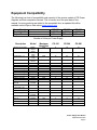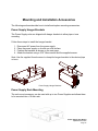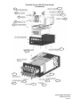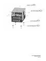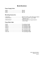
1
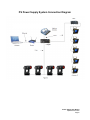
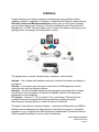
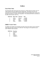
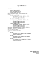
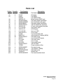
PS-600 PS-300 PS-150 Power Supplies User Manual PS-600 – Model 20600 (600 watts) PS-300 – Model 20300 (300 watts) PS-150 – Model 20150 (150 watts) CONTENTS Declaration of Conformity ..................................................... 3 Safety Information ................................................................. 4 Introduction ........................................................................... 6 System Components............................................................. 7 PS Power Supply............................................................. 7 System Layout Diagram .................................................. 8 Equipment Compatibility......................................................... 9 Installing the Power Supply .................................................. 10 Head-Feet Restrictions......................................................... 11 Mounting and Installation Accessories ................................. 12 Infotrace ............................................................................... 13 Cables .................................................................................. 14 Specifications ....................................................................... 15 Parts List .............................................................................. 16 Exploded Parts Diagram ...................................................... 17 Warranty Information ............................................................ 20 Power Supply User Manual Updated March 2009 Page 2 Power Supply User Manual Updated March 2009 Page 3 Safety Information SAVE THESE INSTRUCTIONS READ AND FOLLOW ALL INSTRUCTIONS This manual gives step-by-step instructions for the preparation, setup, and operation of the PS Power Supply. There is a potential risk of fire, electric shock or injury to persons if the product is not used as instructed. WARNING: When using electrical appliances, use basic precautions, including: • • • Read this manual before connecting power. Use supervision around children. Use in a dry location only. The PS Power Supply is to be used in an indoor environment only and is not intended for residential use. For continued protection against risk of fire, replace only with same type and rating of fuse. Protection against electric shock is assured only if the mains connected power supply cord set is connected to a properly earthed grounding type receptacle. An all pole disconnect device must be located adjacent to the unit or, if the AC cord is used as the main disconnect device, ensure that the socket-outlet is located/installed near the equipment and is easily accessible. THE MAINS LEADS ARE COLORED IN ACCORDANCE WITH THE FOLLOWING CODE AND MUST BE CONNECTED IN THE FOLLOWING SCHEME: - GREEN AND YELLOW: EARTH - BLUE: NEUTRAL - BROWN: LINE WARNING: THIS EQUIPMENT MUST BE EARTHED. For questions, contact Wybron at 1-800-624-0146 or visit www.wybron.com. Product Modification Warning Wybron, Inc. products are designed and manufactured to meet the requirements of United States and International safety standards. Modifications to the products could affect safety and render the product non-compliant to relevant safety standards. Power Supply User Manual Updated March 2009 Page 4 Notes de Sécurité EPARGNER CES INSTRUCTIONS LIRE ET SUIVRE TOUTES INSTRUCTIONS Ce manuel donne des instructions pour la preparation, l’organisation, et l’opération du le PS provision d'électricité. Il y a un risqué de feu, décharge électrique, ou la blessure aux gens si le produit n’est pas utilize comme instruit. AVERTISSEMENT: En utilisant des appareils électriques utilise la prudence fondamentale inclut: • • • Lire ce manuel avant d'alimenter ou l'installation de l'accessoire. Utiliser la prudence près des enfants. Sécher l'emplacement seulement. Le PS provision d'électricité va être utilize à la maison seulement et pas pour l’usage residential. Pour la protection continuée contre le risque de feu, remplacer seulement avec le même type et le même classement de fusible. La Protection contre la décharge électrique est seulement assurée si la série de corde connectée principale est connectée à un convenablement terre de type. Un appareil débranchant doit être localisé à côté de l'unité ou, si la corde de courant alternatif est utilisée comme le principal débranche l'appareil, S'assurer que la douillesortie localise/installé près de l'équipement et est facilement accessible. LES AVANCES PRINCIPAUX SONT CONFORMEMENT COLORES AU CODE SUIVANT ET DOIVENT ETRE CONNECTES DANS L'ARRANGEMENT SUIVANT : vert et jaune– terre bleu – neutre marron – ligne L'AVERTISSEMENT – CET EQUIPEMENT DOIT ETRE FONDE. Pour les questions, Wybron de contact à 1-800-624-0146 ou visite www.wybron.com. L’Avertissement de Modification de Produit Les produits de Wybron, Inc. sont conçus et a fabriqué pour rencontrer les conditions d’Etats-Unis et de norms de sûreté internationals. Les modifications aux produits pourraient affecter la sûreté et rendent le produit non-conciliant aux normes de sûreté pertinentes. Power Supply User Manual Updated March 2009 Page 5 Introduction Wybron's 150-, 300- and 600-watt PS Power Supply units attach easily to a truss or can be mounted into a 19-inch rack. A Power Supply unit can be controlled by one or several DMX512 channels that send DMX signals from the lighting console to each device along with 24 volts DC. Both the signal and the power travel along a single cable, eliminating the need for a separate power cable for each device. Each unit provides power for Wybron's feedback-compatible IT products, which send feedback to their operators using Remote Device Management, an ESTA-standard twoway communication protocol. Power Supply User Manual Updated March 2009 Page 6 System Components Power Supply The power supply accepts DMX512 from a lighting console and passes it along with 24VDC power to each device. This eliminates the need for separate control and power cables to each device. The DMX512 control signal can also be daisy chained to other PS power supplies or other DMX-controlled devices. Caution: The PS Power Supply is compatible with Forerunner devices but NOT the RAM/Coloram II family of devices (i.e. Coloram II, CXI, Goboram II, etc.) DO NOT connect PS compatible devices to RAM/Coloram II Power Supplies, or RAM/Coloram II compatible devices to PS Power Supplies. Damage from such action will not be covered by the equipment warranties. PS Compatible Devices • • • • • • Nexera LX Coloram IT CXI IT Forerunner Eclipse IT Iris Eclipse IT Shutter Refer to the user manuals for detailed operating information on these products. Power/Data Cable The Power/Data Cable connects the Power Supply outputs to the connected devices and provides them with power and control signal. The cable uses 4-pin XLR connectors on either end and consists of two 14 AWG conductors and a 22 AWG twisted, shielded pair. See the “Cable” section of this manual for the pin-out. Power Supply User Manual Updated March 2009 Page 7 PS Power Supply System Connection Diagram Lighting Console 5 pin DMX Four Pin Power Supply User Manual Updated March 2009 Page 8 Equipment Compatibility The following is a chart of compatibility and capacity of the various models of PS Power Supplies and their companion devices. This is current as of the print date of this manual. As more products are added to the compatible line, an updated list will be available on the Wybron Web site at www.wybron.com. Power Supply Model Number Output Power PS-150 20150 150 watts PS-300 20300 300 watts PS-600 20600 600 watts Number of Units per Power Supply Description Model Maximum Head-Feet PS-150 PS-300 PS-600 Nexera LX Tungsten 82560, 82570 82640 2580, 2600 4540 7140 84520 87110 810100 816090 815010 816080 87080 816120 816080 85000 87250 812020 89020 811020 817010 1500 8 16 32 1500 6 12 24 1500 16 32 64 1500 6 12 24 1000 1000 1000 1000 1000 1000 1000 1000 1500 1500 1500 4 6 6 6 5 6 6 6 6 6 8 8 12 12 12 10 12 12 12 12 12 16 16 24 24 24 20 24 24 24 24 24 32 1500 6 12 24 82401 823020 1500 750 6 3 12 6 24 12 1500 6 12 24 CXI IT Lg Format 87200 816120 81605 750 2 5 9 CXI 12” 812210 500 4 9 18 CXI Mariner 87220 1500 6 12 24 CXI MultiPar 87240 1000 4 9 18 Nexera LX CDM Forerunner 4” / 7” Coloram IT 4” / 7.5” Coloram IT 10” Coloram IT Lg Fmt Coloram IT 15” Coloram IT 8 Light Aquaram IT 7.5” Aquaram IT 6 Light Aquaram IT 8 Light Aquaram IT Lg Fmt Eclipse IT Iris 1K Eclipse IT Iris 2K Eclipse IT Shutter 1K / 2K Eclipse IT Shutter Lg Fmt (5K / 16”) Eclipse IT Shutter 24” Eclipse IT Iris 24” CXI IT 4” / 7.5” Power Supply User Manual Updated March 2009 Page 9 Installing the Power Supply 1. Mount the Power Supply The Power Supply is designed to be freestanding, truss-mounted, or rackmounted. The Power Supply comes with a mounting bracket that hooks over the pipe or truss of your lighting rig and is locked into place with a thumb screw. If you use this mounting method, connect the Power Supply's safety cable by clipping it around the pipe or truss. The Power Supply can also be mounted into a 19" rack using the optional rack mount kit. The rack mount kit will accommodate two units side-by-side. 2. Connect the Device to the Power Supply Connect the device to the Power Supply using Wybron’s 4-pin power/data cable. Refer to the HEAD-FEET RESTRICTION section of the manual for details of the length of cable runs. Note: The Wybron Power/Data Cable has been specially designed to minimize voltage drop. Use only Wybron-supplied cable. 3. Connect the Power Supply to AC Power Plug the AC cord into a non-dimmed power circuit. The power supply automatically accommodates 100 – 240V ~ 50/60 Hz. Caution: Do not power the Power Supply from a dimmed circuit. Severe damage will result and is not covered by product warranty. A red LED (viewable from the stage) indicates power. 4. Connect and Set the DMX512 Source Connect the DMX512 signal source to the DMX input connector on the front of the power supply using standard DMX cable. The presence of a valid DMX signal will be indicated by a flashing green LED. Power Supply User Manual Updated March 2009 Page 10 Head-Feet Restrictions The HEAD-FEET parameter is a method of accounting for the voltage drop in the power/signal cable caused by the current drawn by each device. To help understand this issue, think of it as water pressure (voltage) in a hose (cable) where there are multiple water sprinkler heads (color changers). If the hose (cable) is too long, or there are too many sprinkler heads (color changers), the water pressure (voltage) will be too low. HEAD-FEET is defined as "the sum of cable lengths from each device to a single power supply output.” For Head-Feet information on a specific Wybron product, please refer to that product’s user manual. Power Supply User Manual Updated March 2009 Page 11 Mounting and Installation Accessories The following sections describe how to install and replace mounting accessories. Power Supply Hanger Brackets The Power Supply units are shipped with hanger brackets to allow pipe or truss mounting. Follow these steps to install the hanger bracket. 1. 2. 3. 4. Disconnect AC power from the power supply. Place the power supply on its side on a flat surface. Position the brackets as shown on the next page. Attach the bracket using a 3/16" Allen wrench and the supplied screws. Note: Use the supplied thumb screws to clamp the hanger brackets to the desired pipe or truss. Power Supply Hanger Brackets Power Supply Rack Mounting The rack mount accessory can be used with up to two Power Supplies and allows them to be mounted into a 19-inch rack. Power Supply User Manual Updated March 2009 Page 12 Infotrace Imagine checking your lighting equipment and diagnosing any problems without grabbing a ladder or strapping on a harness. It's possible with Wybron's award-winning Infotrace Control and Management System, which gives you the tools to manage your rig without leaving your computer. Using the feedback protocol Remote Device Management, or RDM, Infotrace enables you to inspect and address everything in your lighting system, managing it and knowing that it works. The diagram above outlines Infotrace’s key components, which include: Infogate – The software and hardware required to facilitate the transfer and display of information. Infochip – A conversion chip that can be used with non-RDM equipment to allow communication with the Infogate software. Infostore – An Internet-based application that aggregates data captured by Infogate and allows for the accumulation of historical information related to the equipment performance in the installation. IT Products – Coloram IT, CXI IT, Eclipse IT Iris, and Eclipse IT Shutter all have updated electronics to support RDM communication plus additional product improvements, including sensors to detect a variety of conditions. The heart of the Infotrace system is Infogate — specialized software that uses RDM to facilitate remote addressing and diagnostics for potentially every piece of equipment mounted on a rig. Infogate works with all Wybron-manufactured IT products as well as RDM-compatible equipment from any other manufacturer. Power Supply User Manual Updated March 2009 Page 13 Cables Power/Data Cable The power/data cable uses 4-pin XLR connectors on either end and consists of two 14 AWG conductors and a 22 AWG twisted, shielded pair. The shells of the two XLR connectors are not electrically connected together, preventing large power currents from flowing from chassis to chassis of the equipment. The twisted pair shield is connected at the male XLR connector end only. XLR Pin # 1 2 3 4 Wire Color White Green Red Black Function Ground Data Data + 24VDC Size 14 AWG 22 AWG 22 AWG 14 AWG DMX512 Control Cable The DMX control cable from the lighting console to the power supply is a five-conductor cable with 5-pin XLR connectors on each end. The wiring pin-out is specified by the USITT DMX512/1990 standard. XLR Pin # 1 2 3 4 5 Function Common Data Data + Talkback Talkback + Power Supply User Manual Updated March 2009 Page 14 Specifications Connectors: DMX in: Male 5-pin XLR DMX out: Female 5-pin XLR Output: Female 4-pin XLR DMX512 termination: None – DMX signal pass thru Fuse: PS-600 (model 20600): Input voltage: 100-240V ~ 50/60 Hz 10-5A 250V 7A Slo Blo for 100-120V~ 250V 4A Slo Blo for 220-240V~ PS-300 (model 20300): Input voltage: 100-240V ~ 50/60 Hz 5-3A 250V 4A Slo Blo for 100-120V~ 250V 2A Slo Blo for 220-240V~ PS-150 (model 20150): Input voltage: 100-240V ~ 50/60 Hz 3-1.5A 250V 2A Slo Blo for 100-120V~ 250V 1A Slo Blo for 220-240V~ Input Power: Automatically accepts 100-240V ~ 50/60 Hz Input Signal: 1990 USITT standard DMX512 Red LED: Indicates power Green LED: Indicates DMX signal Size: PS-600: 14”/356mm L x 7.8”/198mm W x 4.1”/104mm H Weight: 7.9 lbs/3.6 kg PS-300: 14"/356mm L x 7.8"/198mm W x 3"/76mm H Weight: 5.4 lbs/2.4 kg PS-150: 12.7"/323mm L x 7.6"/193mm W x 2.9"/74mm H Weight: 3.9 lbs/1.8 kg Power Supply User Manual Updated March 2009 Page 15 Parts List Callout Quantity Part Number (1) 4 SCRFH632150 (2) 8 Z-2287 (3) 1 F0825 1 F6025S (4) 1 2060-01-02 (5) 4 SCHRFHM4X8 (6) 4 SCRPH440025P (7) 4 SCRFHM4X8 (8) 2 SCRFH832037 (9) 1 2024-01-06 (10) 2 67-1160-ND (11) 2 2060-01-03 (12) 2 67-1162-ND (13) 1 2060-02-0011 NC5MP (14) 1 (15) 8 NC4FD-L1 (16) 20 SCRFH440037 (17) 1 NC5FP (18) 1 031-1666 (19) 1 313-007 (20) 1 031-1693 (21) 2 SCRFH632037 (22) 1 10EEA1 (23) 4 SCRPH440037 (24) 1 2060-01-04 (25) 8 SCSRFH632025 (26) 4 704-08-03 (27) 4 SCRPH832037P Description Flat head screw Grommet Fan 600W Fan 300W/150W Board bracket 600W only Flat screw head 4mmX8mm Pan head black with patch Flat screw head 4mmX8mm 3/8 Flat head black stainless 24 way power supply fan plate 5mm green LED LED bracket 5mm red LED Circuit card 5-pin chasis MT male 4-pin chasis MT female (600W) Flat head screw 5-pin chasis MT female Fuse cap round Fuse 7 amp Fuse holder body 3/8 Flat head Power connector filter Pan head screw Top Chassis (600W) Flat head screw Rubber feet Pan head machine black Power Supply User Manual Updated March 2009 Page 16 Exploded View of a PS-600 Power Supply: Part Numbers 12 1 1 11 2 10 3 9 4 5 23 13 14 15 22 20 17 16 18 21 19 Power Supply User Manual Updated March 2009 Page 17 24 25 26 27 Power Supply User Manual Updated March 2009 Page 18 Model Numbers Power Supply Units 20600 ...........................................................PS-600 20300 ...........................................................PS-300 20150 ...........................................................PS-150 Mounting Accessories 715-01-03P...................................................PS-600, PS-300, and PS-150 hanger bracket SCRWC252075 ............................................Wing screw for power supply hanger bracket to pipe SCRSC2520037 ...........................................Socket cap screw for hanger bracket to power supply Power/Data Cable 7042-3 ..........................................................3' power/signal cable 7042-5 ..........................................................5' power/signal cable 7042-10 ........................................................10' power/signal cable 7042-15 ........................................................15' power/signal cable 7042-25 ........................................................25' power/signal cable 7042-50 ........................................................50' power/signal cable 7042-75 ........................................................75' power/signal cable 7042-100 ......................................................100' power/signal cable Power Supply User Manual Updated March 2009 Page 19 Warranty Information WYBRON, INC. warrants to the original owner or retail customer that for a period of one year from date of delivery of a portable system or energization of a permanently installed system (up to a maximum of 18 months from delivery) its products will be free from defects in materials and workmanship under normal use and service. Warranty does not cover any product or part of a product subject to accident, negligence, alteration, abuse, misuse or any accessories or parts not supplied by WYBRON, INC. Warranty does not cover "consumable" parts such as fuses, lamps, or color media. WYBRON, INC.'s warranty does not extend to items not manufactured by us. Freight terms on warranty repairs are FOB WYBRON, INC. factory or designated repair facility. Collect shipments or freight allowances will not be accepted. WYBRON, INC.'s sole responsibility under this warranty shall be to repair or replace at WYBRON, INC.'s option such parts as shall be determined to be defected on WYBRON, INC.'s inspection. WYBRON, INC. will not assume any responsibility for any labor expended or materials used to repair any equipment without WYBRON, INC.'s prior written authorization. WYBRON, INC. shall not be responsible for any incidental, general or consequential damages to property, damages for loss of use, time, profits or income, or any other charges. The owner's obligations during the warranty period under this warranty are to notify WYBRON, INC. at WYBRON, INC.'s address within one week of any suspected defect, and return the goods prepaid to WYBRON, INC. at their factory or authorized service center. This warranty is contingent on the customer's full and timely compliance with the terms of payment set forth in said purchase order. This warranty is expressly in lieu of any and all other warranties expressed or implied including the warranties of merchantability and fitness for a particular purpose and of other obligations and liabilities on our part. The owner acknowledges that no other representations were made to him or relied upon him with respect to the quality and function of the goods sold. This written warranty is intended as a complete and exclusive statement of the terms thereof. Prior dealings or trade usage shall not be relevant to modify, explain or vary this warranty. Acceptance of, or acquiescing in, a course of performance under this warranty shall not modify the meaning of this agreement even though either party has knowledge of the performance and a chance to object Software version 1.0 Manual revision: March 19, 2009 Power Supply User Manual Updated March 2009 Page 20