1
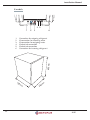
Octopus
Ice Stick
User Manual
Installation Manual, Planning Manual
Three phase 400 V
Dok: AI-01
• IS 48X
• IS 61X
• IS 81X
• IS 48XP
• IS 61XP
• IS 81XP
Copyright © 2009 Octopus Energi AB
This manual contains copyright protected information which is the property of Octopus Energi AB. No part
of this document may be copied or forwarded electronically, or in any other way, without a prior written
permission from Octopus Energi AB. The same rule applies to images in the manual and translation to other
languages.
Edition 1
The right to make changes in this manual is reserved.
This document is produced by
Octopus Energi AB
Box 161
243 23 Höör
Sverige
More copies can be ordered from Octopus Energi AB. When ordering, always refer to the document number
written on the first page of the manual as well as in the footer of each page.
Contents
Introduction
Safety Instructions
Introduction
User Manual
Included Parts
Temperature Setting
Care and Maintenance
Troubleshooting
Recycling and Dismantling
Technical Data
Installation Manual
Checklist
Unpacking and Inspection of Material
Lifting/Unloading
Assembling the Ice Stick
Connect the Ice Stick to the Heat Pump Module
Shape Pipes and Welds
Placement of the Heat Pump Module
Connecting to an Existing Heating System
System Configurations
Assembling and Connecting the Control Panel
Placement of the Air Temperature Sensor
Pressure Test
Vacuum Drive
Glycol
Propane
Operation Start-up
Temperature Setting
Parameter List
Installation Checklist
Wiring Diagrams (Three phase 400 V)
Measurements and Connections
Technical Data
Planning Manual
Electricity
Transport and Storage
Preparations
Additional Heating and Water Heating
4
5
7
9
9
12
14
15
16
17
19
19
19
19
20
21
25
25
26
27
30
30
30
30
31
31
31
33
35
37
38
41
43
44
44
44
44
47
Introduction
Introduction
Congratulations! When you chose the Octopus heat pump, you chose a heat pump system
which is a more energy-saving concept than traditional heat pumps for heating of, and hot
water production for, buildings. The system examines a list of parameters to ensure that the
operation always is machine-friendly and energy-efficient.
The system takes energy from the air in a way that is friendly to the environment. The system
also ensures that there is minimum impact on the environment during installation. Octopus
has developed the system according to the ideology that neither the house owner nor the
environment should be disturbed.
How much heat a house needs, is dependent on many different factors. During a large part of
the year, the house gets enough energy from the sun, people and household appliances. The
house often needs more heat during autumn, winter and spring. How much more is necessary
to keep the house warm, depends on the insulation of the house, the type of domestic heating system installed, the outdoor temperature, the general weather and losses through ventilation.
OctoEL, the control panel of the system, handles this for you by floating condensation, that
is by only producing as much heat as the house needs to maintain an even indoor temperature.
4
AI-01
Introduction
Safety Instructions
Always follow the safety instructions in this manual as well as on signs and markings on and
around the machine in order to prevent damage to person and machinery.
The heat pump may only be used in accordance with the instructions in this manual. All other
use is forbidden. Incorrect use caused by not following the instructions in this manual may
result in damage to property, and at worst in personal injury.
If problems arise with the Ice Stick heat pump, refer to the Troubleshooting chapter before
you contact Octopus. If you need a service engineer, only contact authorized service engineers. All adjustments, other than room temperature and additional heating adjustments are
strictly forbidden.
All maintenance work must only be carried out by Octopus Energi AB or authorized personnel.
This document should be kept for the lifetime of the heat pump.
Manual Symbols
The following symbols occur in the manual to help you when you read the directions.
WARNING!
Make sure that the
current is disconnected
before any maintenance
work is started.
Safety directions. This symbol is used when
a dangerous situation may arise.
NOTE!
It is important that
all radiators are completely open in order
for the heat pump to
work optimally.
AI-01
Advice. This symbol is used when we want
you to pay attention to something important.
5
Introduction
Machine Signs
CE - Sign
High Voltage Sign
6
AI-01
Introduction
Introduction
System Description
The system consits of a control panel (OctoEL) (1), a heat pump module (2) and the evaportor, Ice Stick (3). Depending on the configuration, the heat pump module can be placed
together with the evaporator or inside the house.
The heat pump heats the water-borne system of the house by gathering free energy from the
outside. The control panel manages the operation of the heat pump and the additional heating of the house using an indoor temperature sensor, ensuring that an even temperature is
maintained irrespective of the weather.
The heat pump module
placed together with the Ice
Stick.
1
2
3
1.
2.
3.
AI-01
Control panel (OctoEL)
Heat pump module
Evaporator/Ice Stick
The heat pump module placed inside the house
7
Introduction
Operation
Two copper pipes are connected to the evaporator. One pipe transfers fluid to the Ice Stick.
The other pipe transfers energy filled gas to the heat pump module. Energy is transferred
to the buildings water-bourne system by the heat pump module. The heated water is then
pumped around the building.
1. The heat gathering part - low pressure
This part of the heat pump is called the evaporator (Ice Stick). A refrigerant (propane) with a low
temperature flows through the Ice Stick. The Ice
Stick is heated by its surrounding environment,
evaporating the refrigerant.
2. The preassure rising part - High pressure
This part consists of a compressor. The heated
and evaporated refrigerant is compressed by the
compressor. The increase in pressure raises the
temperature and condensation point (the point
where gas returns to liquid form).
3. The heat emitting part - High pressure
This part of the heat pump transfers the heat to
the house and is called the condensor. The refrigerant passes through the condensor at a high temperature and condensation point. In the condensor,
the refrigerant is cooled down by the heating system of the house (such as radiators or floor heating), leading to the condensation of the refrigerant
(returning it to liquid form).
0 to -30°C
Heat pump module
+20 to +50°C
4. Pressure lowering part - Low pressure
This part consists of a throttling device. The
cooled refrigerant expands and both the temperature and the boiling point of the refrigerant is significantly lowered as a result of the lower pressure.
8
AI-01
User Manual
User Manual
Included Parts
Evaporator/Ice Stick
The Ice Stick consists of a number of energy sticks. The amount of energy sticks are dependant on which heat pump you have. An energy stick consists of 2 meters of copper piping
that are enclosed in aluminium profiles which gives an area equivalent to 64 meters of copper
piping (22mm). For example, the IS48 consists of 12 energy sticks with a total area equivalent
to 770 meters of copper piping. The propane inside the copper piping draws energy from the
surrounding air water vapour. The Ice Stick has no moving parts and does not require defrosting.
Propane
The heat pumps refrigerant circuit is filled with the refrigerant R290 (CH3, CH2, CH3 Propane). R290 has no effect on the ozone and has a negligible direct greenhouse effect. Propane
has no colour or scent. To be able to detect a leak an odorant has been added to the propane,
resulting in the characteristic propane scent. Propane is not toxic but it is highly flammable.
When water vapour looses energy it returns to liquid (condensation), thereafter freezing to ice.
Energy is released in every step. The creation of 1,4kg of ice saves 1 kWh. The liquid propane absorbs the energy within the copper piping of the energy stick and evaporates completely when it passes through all of the energy sticks.
Heat Pump Module
The heat pump module consists of the following:
1. A compressor. The compressor increases the pressure on the refrigerant and in doing so
increases the temperature.
2. A heat exchanger (the condenser). Within the heat exchanger the hot gas transfers its
energy to the water-borne system.
3. A junction box. The control panel is to be plugged into the switch box.
4. A vibration damper
5. A high pressure sensor
6. A low pressure sensor
7. Flameproof insulation
8. A safety switch
9. CE-sign
10. A drying filter
AI-01
9
User Manual
1
5
4
10
2
3
7
8
1.
2.
3.
4.
5.
6.
7.
8.
9.
10.
Heat exchanger
Compressor
Junction box
Vibration damper
High pressure sensor
Low pressure sensor
Flameproof insulation
Safety Switch
CE-Sign
Drying filter
9
6
On the top side of the XP model heat pump modules there are two pipes (inflow and outflow) for the refrigerant and two pipes (inflow and outflow) for water.
1.
2.
3.
4.
1
10
2
3
Water, out (red)
Water, in (blue)
Refrigerant, out
Refrigerant, in
4
AI-01
User Manual
Control Panel (OctoEL)
The control panel controls the heating system for the entire house and has two digital thermostats.
The digital thermostat on the left, control panel 905, controls the temperature in the room
where the air temperature sensor is placed. The air temperature sensor is to be placed in a
suitable location in the house. Read more about the air temperature sensor below.
The digital thermostat on the right, control panel 902, controls the temperature of the hot
water from the heat exchanger. This control panel also controls the pressure in the compressor (high or low pressure).
Control panel 905, air temperature regulation
Control panel 902, heat pump protection
1
1
out 1
out 2
out
set
set
eWDR905T
2
4
5
6
eWDR902T
2
4
3
1.
2.
3.
4.
5.
6.
Display
Select up
Settings
Select down
out 1
out 2
5
3
1.
2.
3.
4.
5.
Display
Select up
Settings
Select down
out
Air Temperature Sensor
The air temperature sensor measures the actual temperature of the room/house. The sensor
provides data for the heat pump control panel to work with.
It is important that the air temperature sensor is placed in a room (or in a location) in the
house where the highest average temperature is required. The air temperature sensor has to be
placed where it is changed by the Octopus heating system of the room/house such as floor
heating and radiators and not by local sources of heat such as lamps, stoves, and direct sunlight. The air temperature sensor should not be placed on external walls.
AI-01
11
User Manual
Temperature Setting
Temperature Regulation
The regulation of the temperature in the house is done with the left control panel, control
panel 905. The factory default setting air temperature setpoint is 20°C.
When the air temperature sensor measures a temperature that is 0.1°C below the control panel
value the compressor is started with a delay of 500 seconds. If the measured temperature is
0.5°C below the control panel value the boost is started, this also occurs with a delay of 500
seconds. If floor heating is used the boost should be set to not start until the measured temperature is 1.0°C below the control panel value.
When there is no temperature difference between the air temperature sensor value and the
control panel value the compressor and the additional heating is turned off. This is done with
a delay of 500 seconds.
The heat pump has a default setpoint setting of 20°C. To change the air temperature setpoint
carry out the following procedure:
1. Press set once. LED out 1 should flash.
2. Use the blue or red arrow to set the desired temperature value.
3. Press set until LED out 2 is flashing.
4. Use the blue or red arrow to set the temperature value to the same as in step 2.
5. Press set repeatedly to verify that the same value is shown in the display.
Control panel 905, air temperature regulation
Control panel 902, heat pump protection
1
1
out 1
out 2
out
set
set
eWDR905T
2
4
5
6
eWDR902T
2
4
3
1.
2.
3.
4.
5.
6.
12
Display
Select up
Settings
Select down
out 1, heat pump
out 2, additional heating
5
3
1.
2.
3.
4.
5.
Display
Select up
Settings
Select down
out
AI-01
User Manual
Heat Pump Protection
NOTE!
This value must only
be changed by
Octopus Energi AB or
authorized personnel.
The digital thermostat to the right, control panel 902, shows the current water temperature
after the heat pump. The factory setting is 55°C and must only be changed by Octopus Energi
AB or authorized personnel.
The compressor is automatically shut off at the setpoint value (55°C) to protect the compressor and it is started again when the water temperature is 5°C below the setpoint value.
Additional Heating
Additional heating should be installed if it is not already installed.
During the coldest months of the year the heat pump might need additional heating to keep
a constant temperature within the building. If the heat pump is forced to maintain an indoor
temperature that is higher than its performance capacity and no additional heating is available
it has to work continuously, thus not giving the heat pump the off times it needs. This can
result in the evaporator freezing up to a point when its efficiency is lowered.
The different heat pump modules can be connected to all water-bourne systems such as district heating, electric element, oil- , gas-, or pellet boiler.
Radiators
NOTE!
All radiators must
have open valves in
the rooms that are to
be heated.
AI-01
13
User Manual
Care and Maintenance
Controls
Check the Ice Stick for frost periodically to ensure that the heat pump is working as intended.
If the heat pump should stop functioning, consult the troubleshooting section of this manual.
If the problem persists, contact your installation technician for further instructions and assistance.
Defrosting of the Ice Stick
Defrosting of the Ice Stick is done automatically.
Change of Components
NOTE!
Change of components
must only be performed
by authorized personnel.
When a component is changed the new component must be equivalent to the original.
When changing the compressor the filter must be change as well.
Only solder in a well-ventilated area.
14
AI-01
User Manual
Troubleshooting
Description
Probable Cause
The house is not getting warm
The settings for the control panel Check the settings for the conare wrong
trol panel (see Control Panel,
page 11)
The additional heating is not
Contact your installation techworking
nician
During extreme or long-running • Open all thermostats in the
cold weather this can be normal
house, deareate the
radiators/system
May be caused by either too
•
Check that the circulation
much or not enough refrigerant
pump is operating
May be caused by bad circula• Contact your installation
tion within the house
technician
If the weather is warm this can
Contact your install technician
be normal, otherwise there is not
enough refrigerant
The electrical phase is wrong
Turn off the heat pump with
the motor protection (safety
switch and contact your installation technician/electrician
The motor protection is tripped / Reset the safety fuse followed
the safety fuse is tripped
by the motor protection.
Contact your installation technician
Faulty temperature sensor/bad
Contact your installation techconnection
nician/electrician
The right display is turned off
The Ice Stick is only partly
frozen
The heat pump is loud and
does not produce heat
The compressor does not start
The display is showing “EEE”
AI-01
Solution
15
User Manual
Recycling and Dismantling
NOTE!
All current to the
heat pump must be
disconnected before
dismantling can
begin.
When the heat pump is to be dismantled and recycled, follow these instructions:
• Draining of the refrigerant must be performed by accredited personnel.
• The compressor shall be sent to an appropriate recycling centre.
• All other hardware shall be sorted and recycled.
16
AI-01
User Manual
Technical Data
Technical Data
Model OctopusTM IS
Unit
IS48X/XP
IS61X/XP
IS81X/XP
Aluminium profiles
Electrical connection
Fuse
Compressor, type
Compressor, input
Compressor, output
capacity
Max temperature
Refrigerant,
Propane/R290
Pressure min/max
Temperature,
boil/condense
Dimensions, evaporator
(WxDxH)
Dimensions, heat pump
module (WxDxH)
Weight, evaporator
Weight, heat pump
module
Control panel
pc
12
2 x 12
A
10D
kW
m3/h
3,0
11,41
12
400V, N3-Phase
10D
Scroll
3,7
14,4
~1
55
~1
AI-01
C
kg
O
bar
o
C
mm
5,0
19,2
~2
0,5/22
-33/+64
810x980x2220
810x980x2220
2 x 810x980x2220
97
87
590x500x730 (XP)
360x708x625 (X)
97
92
2 x 97
102
OctoEL 10
OctoEL 10
OctoEL 16
mm
kg
kg
16D
17
DECLARATION OF CONFORMITY/MANUFACTURER´S DECLARATION
FÖRSÄKRAN OM ÖVERENSSTÄMMELSE/TILLVERKARDEKLARATION
Directive area
Direktivets område
Directive no
Direktiv nr
Safety of machinery
Maskindirektivet
98/37/EG
Low voltage equipment
Lågspänningsdirektivet
2006/95/EC
Electromagnetic compatibility
Elektromagnetisk compatibilitet
2004/108/EC
Pressure equipment
Tryckbärande anordning
97/23/EC
article 3.3
Manufacturer name, address, telephone and fax no:
Tillverkarens namn, adress, telefon och faxnummer:
Octopus Energi AB
Box 161, SE-243 23 Höör, Sweden
Telephone: +46(0)413-51 05 00, Fax: +46(0)413-51 05 01
Brand name or trademarke
Fabrikatnamn eller varumärke
Type of equipment
Typ av utrustning
Heat pump 1-phase 220 V and 3-phase 380 V
Värmepump 1-fas 220 V och 3-fas 380 V
Type designation etc.
Typbeteckning etc.
Name
Namn
Size
Storlek
IS
28, 48, 61, 81, 109
By signing this document, the undersigned declares as manufacturer that the equipment in question
complies with the protection requirements of the above directive.
Genom att underteckna detta dokument försäkrar undertecknad såsom tillverkare att angiven utrustning
uppfyller skyddskraven i rubricerade direktiv.
Date / Datum
Signature / Underskrift
2009-06-29
Position / Befattning
Head of R&D / Utveckl.chef
______________________________
Clarification / Namnförtydligande
Kurt Karlsson
Installation Manual
Installation Manual
Checklist
Before starting the assembly, check that the actions listed below are attended to:
• Construction of Ice Stick concrete plinth
• Space requirements in regards to installation and services
• Dimensions of pipe and canal connections
• Holes in the wall for pipes and cables
• Supply of electricity
If any of these items are not attended to, please follow the instructions in the Planning
Manual.
Before starting the assembly, check that the actions listed below are attended to:
• Same current on all electrical phases (not required when single phase)
• Capacity of the main fuse (it must be suitably rated)
Unpacking and Inspection of Material
Unpack the material and check to see that it has nothing missing or anything damaged due to
transportation. Any damages due to transportation should be immediately reported to Octopus.
Lifting/Unloading
Consider the following when lifting/unloading the Ice Stick and the heat pump module:
• Be careful not to damage the material when lifting and unloading.
• A lifting device or a minimum of 4 people are recommended when unloading.
• The heat pump module must only be transported in the vertical position.
NOTE!
Secure tightly to ensure that the units are
unable to turn over or
slide out of the lifting
device.
AI-01
19
Installation Manual
Assembling the Ice Stick
NOTE!
Octopus does not
recommend installing
the Ice Stick on a roof or
a wall. Octopus claims
no responsibility what
so ever in the event of a
roof or wall installation.
NOTE!
Make sure not to
damage the pipes
when lifting the Ice
Stick from a lying to a
standing position.
Consider the following before starting the assembly of the Ice Stick:
• The Ice Stick should be placed where it will best extract heat from rain, wind and sun.
Perform the following when assembling the Ice Stick:
1. Drill four holes in the concrete plinth where the Ice Stick is to be placed.
2. Secure the Ice Stick in the concrete plinth with four 100mm M10 anchor bolts.
20
AI-01
Installation Manual
Connect the Ice Stick to the Heat Pump Module
Model IS48XP and IS61XP (compressor and heat exchanger within the
house)
1.
2.
3.
4.
Fill the trench between the Ice Stick and the house with 100mm of sand.
Connect a 3/8” (0,85mm) copper pipe to the 1/4” pipe on the left-hand side.
Connect a 7/8” (1,15mm) copper pipe to the 22mm diameter pipe on the right-hand side.
Insulate the pipes at a lenght of one meter from the foundation the house wall with
13mm insulation. Place the pipes within the same insulation.
Lead the pipes into the house through a Ø110mm wavin pipe. The wavin pipe will protect
against moisture.
Place the pipes close together on the sand bed and tie them together with cable ties.
Cover the pipes with 100mm of sand.
Fill the trench with soil.
5.
6.
7.
8.
40cm
2
3 4
1.
2.
3.
4.
3
1m
20cm
1m
1
1
Soil
Sand bed
3/8” copper pipe
7/8” copper pipe
2
All soldering and
shaping of pipes are
to be performed
according to the
instructions in this
manual, see page 25.
AI-01
1m
NOTE!
3
1.
2.
3.
4.
3/8” copper pipe
7/8” copper pipe
13mm insolation
House wall
4
21
Installation Manual
Model IS81XP
1. Fill the trench between the house and the Ice-Sticks with 100mm sand.
2. Connect the 3/8 ”* 0.85 mm copper pipe to the T-connection.
3. Connect the 7/8 ”* 1,15 mm copper pipe to the Ø22mm tube on the right side of the IceSticks. 7/8 ” pipes have to have the same length.
4. Connect the both 34TUB with same length of 3/8” pipe to a T-connection.
5. Insulate the pipes at a lenght of one meter from the foundation the house wall with 13mm
insulation.
6. Lead the pipes into the house through two Ø110mm wavin pipe. The wavin pipe will protect
against moisture.
7. Place the 3/8” and one of the 7/8” pipe closely on the sand bed and tie them together with
cable ties.
8. 7/8” pipes should be 1 m apart.
9. Cover the pipes with 100mm of sand.
10. Fill the trench with soil.
5
6
1m
3
1
2
3/8” copper pipe
7/8” copper pipe
13mm insulation
House wall
34TUB
3/8” copper pipe
3
1m
1.
2.
3.
4.
5.
6.
4
22
AI-01
Installation Manual
Model IS48X and IS61X (compressor and heat exchanger at Ice Stick)
1. Fill the trench between the Ice Stick and the house with 100mm of sand.
2. Connect a Ø28mm insulated water pipe to the connection underneath the heat pump
module marked with a blue colour. The blue connection is for incoming water.
3. Connect a Ø28mm insulated water pipe to the connection underneath the heat pump
module marked with a red colour. The red connection is for outgoing water.
4. Connect the electric cables to the heat pump module.
5. Place the duo insulated pipe in a culvert.
6. Lead the culvert into the house.
7. Lead the electric cables into the house through a wavin pipe. The wavin pipe will protect
against moisture.
8. Place the culvert on the sand bed.
9. Place the electric cables on the sand bed. Mark with plastic strips for electric cables.
10. Cover the culvert with 100mm of sand.
11. Place ground insulation sheets on top of the sand bed
for extra insulation.
12. Fill the trench with soil.
40cm
1m
1
5
20cm
5
2
6
1.
2.
3.
4.
5.
6.
7.
AI-01
34
4
7
1
Soil
Sand bed
Ø28mm insulated water pipe
Ø28mm insulated water pipe
Ground insulation plate
Culvert
Electric cabel
1. Ø28mm insulated water pipe
2. Ø28mm insulated water pipe
3. Culvert
4. Electric cabel
5. Ground insulation plate
6. House wall
2
3
6
23
Installation Manual
Model IS81X (compressor and heat exchanger at Ice Stick)
1.
2.
3.
4.
5.
6.
7.
8.
9.
10.
11.
12.
13.
14.
Fill the trench between the Ice Stick and the house with 100mm of sand.
Open the pipe connection on the left Ice Stick.
Connect the two Ice Sticks with Ø22mm copper pipes.
Connect a Ø28mm insulated water pipe to the connection underneath the heat pump
module marked with a blue colour. The blue connection is for incoming water.
Connect a Ø28mm insulated water pipe to the connection underneath the heat pump
module marked with a red colour. The red connection is for outgoing water.
Connect the electric cables to the heat pump module.
Place the duo insulated pipe in a culvert.
Lead the culvert into the house.
Lead the electric cables into the house through a plastic tube. The tube will act as protection against moisture.
Place the culvert on the sand bed.
Place the electric cables on the sand bed. Mark with plastic strips for electric cables.
Cover the culvert with 100mm of sand.
Place ground insulation sheets on top of the sand bed for extra insulation.
Fill the trench with soil.
7
Open the pipe connection on the left Ice Stick.
5
4
2
1
Connect the two Ice Sticks with Ø22mm copper pipes.
1.
2.
3.
4.
5.
6.
7.
24
Ø28mm insulated water pipes
Ø28mm insulated water pipes
Culvert
Electrical cable
Ground insulation sheet
House Wall
Ø22mm copper pipe
3
6
AI-01
Installation Manual
Shape Pipes and Welds
All laying and shaping of pipes to be carried out by accredited personnel according to industry standards.
When joining two copper pipes, a 5% silver solder is to be used.
When joining a copper pipe to corrosion free metal, a 55% silver solder is to be used.
Placement of the Heat Pump Module
NOTE!
Only valid for models
IS 48XP, IS 61XP and
IS 81XP
• The heat pump module must stand upright, that is with a 0% slope of the floor.
• The heat pump module should always be accessible for service. The working space in front
of the heat pump module must be at least 1,2 meter, see page 41-42 for measurements.
• No heavy objects is to be placed on top of the heat pump module.
• Do not jump/step/stand on the heat pump module.
• The floor in the room where the heat pump module is placed should be dry. Make sure
that there are no posibilities for water to enter the heat pump module, for example from
the ceiling.
• No objects are to be hung on the piping of the heat pump module.
AI-01
25
Installation Manual
Connecting to an Existing Heating System
NOTE!
NOTE!
Octopus recommends
installing preheating
when tap hot water
is to be heated (see
page 27-29 for more
information).
The Ice Stick shall not
be connected to an
accumulation tank.
Octopus recommends using flexible connection hoses for vibration dampening when connecting the heat pump module to an existing heating system.
The following applies when connecting water pipes to the heat pump module, regardless of
model:
• The connection for incoming water is marked with blue.
• The connection for outgoing water is marked with red.
1
2
1
XP - model
1.
2.
26
2
X - model
Connection for incoming water to the heat pump module
Connection for outgoing water
AI-01
AI-01
1. Expansion vessel
2. Electrical water heater
3. Pipe sensor,
protects the compressor against unnecessary load
4. Circulation pump
Floor heating
Radiator
Additinal heating is activated if the temperature
falls 0,5 degrees under the set value
The air tmperature sensor starts the heat pump
when the temperature drops 0,1 degrees
Heat bearer
Water
Control cable
2
Water in
Oil-, Gas-,
Pellet boiler
etc.
(Additional)
4
OctoEL,
Octopus control panel
3
1
Installation Manual
System Configurations
T1
27
28
1. Expansion vessel
2. Electrical water heater
3. Pipe sensor, protects the compressor against unnecessary load
4. Circulation pump
5. Electrical element (additional heating)
6. Plate heat exchanger, enables pre-heating of hot water
Floor heating
Radiator
Additinal heating is activated if the temperature
falls 0,5 degrees under the set value
The air tmperature sensor starts the heat pump
when the temperature drops 0,1 degrees
AI-01
6
Water in
Heat bearer
Water
Control cable
2
5
OctoEL,
Octopus control panel
3
4
1
Installation Manual
T2
AI-01
1. Expansion vessel
2. Electrical water heater
3. Pipe sensor, protects the compressor against unnecessary load
4. Circulation pump
5. Electrical element (additional heating)
6. Plate heat exchanger, enables pre-heating of hot water
Floor heating
Radiator
Additinal heating is activated if the temperature
falls 0,5 degrees under the set value
The air tmperature sensor starts the heat pump
when the temperature drops 0,1 degrees
Heat bearer
Water
Control cable
Refrigerant
2
Water in
6
5
4
Heat pump
OctoEL,
Octopus control panel
1
Ground loop
Installation Manual
T3
29
Installation Manual
Assembling and Connecting the Control Panel
NOTE!
The heat pump
module shall always
be connected to a
permanent electrical
installation.
•
•
The control panel should be be installed near the heat pump module if the heat pump
module is placed indoors.
All electrical work is to be done by authorized personnel according to the wiring diagrams
(see pages 38-40).
Placement of the Air Temperature Sensor
It is important that the air temperature sensor in the house is placed in the room (or location)
where the highest average temperature is required. It is also important that the air temperature
sensor is placed in the room where it is affected by the Octopus heating system of the room/
house, such as floor heating and radiators, and not by any local heat source such as lamps,
stoves or direct sunlight. The air temperature sensor should not be placed on external walls.
Pressure Test
A pressure test is performed to check that all parts of the refrigerant will mechanically keep
for the normal running pressure in the facility. This is done with nitrogen gas.
Perform the pressure test according to industry standard.
Vacuum Drive
The two things that is desired to accomplish by performing a vacuum drive are:
1. Acquire a system that is completely free of any other gas than the refrigerant.
2. Acquire a system that is completely without moisture.
Perform a vacuum drive according to industry standard.
30
AI-01
Installation Manual
Glycol
NOTE!
Only valid for models
IS 48X, IS 61X and
IS 81X
Glycol can be added to protect the condensor from frostburst.
Propane
NOTE!
Refill of propane
(R290) is only to be
performed by
accredited personnel.
NOTE!
Refill of propane
(R290) is done at
operation start-up.
Operation Start-up
NOTE!
To be able to quickly start the compressor, the setting for “od” on
the control panel displays must be changed (see Delay Setting on
page 34). In operation mode this is set to 500 seconds but can be
set to 0 seconds during operation start-up or service.
Models IS48XP, IS61XP, IS81XP and IS81X
•
•
•
•
•
•
•
•
•
•
•
AI-01
After a pressure test and a vacuum drive are performed on the heat pump, refrigerant can be
added.
Connect a manometer to the valves of the low- and high pressure pipes.
Add refrigerant until the right-hand side display of the control panel is lit. This occurs at 1,5 bar.
The compressor can now be started, letting it draw additional refrigerant from the low pressure
pipe.
When the Ice Sticks are halfway frozen additional refrigerant should be added a little at a time.
Wait a few minutes to see how far the frost has spread.
When the Ice Sticks are frozen all around it must be checked that the condensation does not
exceed the flow temperature by more than 5 degrees.
If the condensation is exceptionally high this might be because there is to much refrigerant in the
system or it might be due to bad circulation.
Bad circulation is usually caused by:
The circulation pump
Air in the system
Closed valves
The water flow has been wrongly connected through the heat pump
31
Installation Manual
Models IS48X and IS61X
The models IS48X and IS61X are filled with refrigerant when delivered.
•
•
•
Connect a manometer to the valves of the low- and high pressure pipes.
When the Ice Sticks are frozen all over it must be checked that the condensation does
not exceed the flow temperature by more than 5 degrees.
If the condensation is exceptionally high this might be because there is to much refrigerant in the system or it might be due to bad circulation.
Bad circulation is usually caused by:
• The circulation pump
• Air in the system
• Closed valves
• The water flow has been wrongly connected through the heat pump
Compressor Startup (only three phase unit)
The compressor is a three-phase unit that is sensitive to the rotation direction and can be
damaged if it is operation with a faulty rotation direction during longer periods of time. To
change the rotation direction, switch two incoming phases. Check the compressor drive at
operation start-up.
During normal operation:
1. The peak pressure increases rapidly
2. The suction pressure decreases rapidly
3. The hot gas pipe is warm within 5-10 seconds after start-up
During faulty rotation direction:
1. The compressor is loud
2. The peak pressure does not changed
3. The suction pressure does not changed
Refilling and Deareating
After operation start-up of the heat pump the following is to be checked:
1. The water pressure
2. That there is no air in the radiator circuit or in the circulation pump
32
AI-01
Installation Manual
Temperature Setting
Temperature Regulation
The regulation of the temperature in the house is carried out by the left control panel, control
panel 905. The factory default setting air temperature setpoint is 20°C.
When the air temperature sensor measures a temperature that is 0.1°C below the control panel
value the compressor is started with a delay of 500 seconds. If the measured temperature is
0.5°C below the control panel value the boost is started, this also occurs with a delay of 500
seconds. If floor heating is used the boost should be set to not start until the measured temperature is 1.0°C below the control panel value.
When there is no temperature difference between the air temperature sensor value and the
control panel value the compressor and the additional heating is turned off. This is done with
a delay of 500 seconds.
The heat pump has a default setpoint setting of 20°C. To change the air temperature setpoint
carry out the following procedure:
1. Press set once. LED out 1 should flash.
2. Use the blue or red arrow to set the desired temperature value.
3. Press set until LED out 2 is flashing.
4. Use the blue or red arrow to set the temperature value to the same as in step 2.
5. Press set repeatedly to verify that the same value is shown in the display.
Control panel 905, air temperature regulation
Control panel 902, heat pump protection
1
1
out 1
out 2
out
set
set
eWDR905T
2
4
5
6
eWDR902T
2
4
3
1.
2.
3.
4.
5.
6.
AI-01
Display
Select up
Settings
Select down
out 1, heat pump
out 2, additional heating
5
3
1.
2.
3.
4.
5.
Display
Select up
Settings
Select down
out
33
Installation Manual
Heat Pump Protection
The digital thermostat to the right, control panel 902, shows the current water temperature
after the heat pump. The default setpoint value is 55°C.
To change the setting value, perform the following:
1. Press set until LED out is flashing.
2. Use the blue or red arrow button to set the desired value.
The compressor is automatically shut off at the setpoint value (out) to protect the compressor
and it is started again when the water temperature is 5°C below the set value.
Delay Setting
The factory setting for delay time is 500 seconds. During operation start-up or service this
value can be set to 0 seconds. After operation start-up or service the value must be reset.
To change these values, perform the following in both control panels:
1. Press and hold set until ‘d1’ is displayed.
2. Use the blue or red arrow button until ‘od’ is displayed.
3. Press and hold set and use the blue or red arrow button to set the desired value.
Note that the delay time is to be reset to 500 seconds.
34
AI-01
Installation Manual
Parameter List
Parameter List EWDR 905 C PTC 220V (left digital thermostat)
Parameter
d1
d2
db
LS1
LS2
HS1
HS2
od
Lci
Hci
CAL
OCO
HC1
HC2
dp
tAp
AI-01
Description
Range
Differential
Differential
Neutral state zone
1
Lowest set value for user
min
Lowest set value for user
min
Highest set value for user
max
Highest set value for user
max
Relay time delay
0-500
Lowest current value (4mA)
relative to shown value
Highest current value (20mA)
relative to shown value
Calibration of operation sensor
0
Connections of relay sockets
in
H/C
Relayfunction H=activated when
lowered C=activated when elevated
Relayfunction H=activated when
H/C
lowered C=activated when elevated
Selection of decimal point on=with,
on / oF
oF=without
Factory setting
Unit
o
C
C
o
C
o
C
o
C
o
C
o
C
sek
o
o
Factory Setting
-0,1
-0,5
-5
-5
50
50
500
C
in
H
H
on
35
Installation Manual
Parameter List EWDR 902 T PTC 220V (right digital thermostat)
Parameter
d1
LS1
HS1
od
Lci
Hci
HC1
dp
tAp
36
Description
Range
Differential
Lowest set value for user
min
Highest set value for user
max
Relay time delay
0-500
Lowest current value (4mA)
relative to shown value
Highest current value (20mA)
relative to shown value
Relayfunction H=activated when
H/C
lowered C=activated when elevated
Selection of decimal point on=with,
on / oF
oF=without
Factory setting
Unit
o
C
C
o
C
sek
o
Factory Setting
-5
-5
55
500
H
on
AI-01
Installation Manual
Installation Checklist
Serial Number
Installation Date
Installtion Technicians
Pressure Test
Passed
Failed
Vacuum Drive
Passed
Failed
Additional Heating
Electric Element
Oil Boiler
Gas Boiler
Pellet Boiler
District Heating
_____________________
Heating System
Radiators
Air Heating Aggregate
Supply Air Aggregate
Floor Heating
_____________________
AI-01
37
Installation Manual
Wiring Diagrams (Three phase 400 V)
38
AI-01
Installation Manual
AI-01
39
Installation Manual
40
AI-01
Installation Manual
Measurements and Connections
XP-models
5
6
2
3 4
730mm
1
50
m
0m
m
1.
2.
3.
4.
5.
6.
AI-01
m
90
5
Ø connection for outgoing water
Ø connection for incoming water
Ø connection for outgoing refrigerant
Ø connection for incoming refrigerant
Ø electrical connection
Ø electrical connection
41
Installation Manual
X-models
4 5
1
6
3
Connection for outgoing refrigerant
Ø connection for incoming water
Ø connection for outgoing water
Ø electrical connection
Ø electrical connection
Connection for incoming refrigerant
625mm
1.
2.
3.
4.
5.
6.
2
70
m
8m
m
42
0m
36
AI-01
Installation Manual
Technical Data
Technical Data
Model OctopusTM IS
Unit
IS48X/XP
IS61X/XP
IS81X/XP
Aluminium profiles
Electrical connection
Fuse
Compressor, type
Compressor, input
Compressor, output
capacity
Max temperature
Refrigerant,
Propane/R290
Pressure min/max
Temperature,
boil/condense
Dimensions, evaporator
(WxDxH)
Dimensions, heat pump
module (WxDxH)
Weight, evaporator
Weight, heat pump
module
Control panel
pc
12
2 x 12
A
10D
kW
m3/h
3,0
11,41
12
400V, N3-Phase
10D
Scroll
3,7
14,4
~1
55
~1
AI-01
C
kg
O
bar
o
C
mm
5,0
19,2
~2
0,5/22
-33/+64
810x980x2220
810x980x2220
2 x 810x980x2220
97
87
590x500x730 (XP)
360x708x625 (X)
97
92
2 x 97
102
OctoEL 10
OctoEL 10
OctoEL 16
mm
kg
kg
16D
43
Planning Manual
Planning Manual
Electricity
The heat pump module shall always be connected to a permanent electrical installation. We
define a permanent electrical installation to be a connection to a power distribution grid.
The size of the incoming cable and fuse size of the local utility should be large enough for the
proposed installation.
Transport and Storage
The heat pump is delivered on europallets. If there is a delay before assembly and connection,
consider the following:
• The heat pump should be placed in a dry location indoors.
Consider the following during the transport of the Ice Stick and the heat pump module:
• Be careful not to damage the material when lifting and unloading.
• A lifting device or a minimum of 4 people are recommended when unloading.
• The heat pump module must only be transported in the upright position.
Preparations
Placement of the Ice Stick
We recommend that the location for the placement of the Ice Stick is as windy and sunny as
possible, preferably at the southern end of the building. The distance from the building to the
Ice Stick should be at least one meter from the outer wall. If the building is L-shaped, avoid
placing the Ice Stick within the inner angle of the building.
44
P-01
Planning Manual
The Concrete Plinth and Assembly of the Ice Stick
The Ice Stick should be assembled onto a concrete plinth measuring 1000*1000*300mm (see
image). If there are two Ice Sticks, they should be assembled onto a concrete plinth measuring
2500*1000*300mm (see image).
The concrete plinth can either be cast in concrete or constructed by firmly secured cement
blocks. Another type of construction can be used provided it can handle a load of up to
400kg plus wind.
1000mm
300mm
1000mm
300mm
Concrete plinth for model IS48X/XP and IS61X/XP
1000mm
2500mm
Concrete plinth for model IS81X/XP
P-01
45
Planning Manual
Digging the Trench
A trench is dug between the concrete plinth and the house wall. The dimension of the trench
can be 400*1000mm (see image). The dimension of the trench can vary due to the soil. When
installing an XP model, note that there is a risk of freezing around the trench.
1000mm
400mm
Penetration of Walls/Floors
NOTE!
Shall only be performed
by accredited personnel.
NOTE!
Consider the risk of
freezing within the
walls.
Placement of the Heat Pump Module
NOTE!
Only valid for models
IS 48XP, IS 61XP and
IS 81XP
46
P-01
Planning Manual
•
•
•
•
•
•
The heat pump module must stand upright.
The heat pump module should always be accessible for service.
No heavy objects is to be placed on top of the heat pump module.
It is forbidden to jump/step/stand on the heat pump module.
No objects are to be hung on the piping of the heat pump module.
The working space in front of the heat pump module should be at least 1,2 meter.
The measurements (WxDxH) of the heat pump module are 590mm x 500mm x 730mm.
Placement of the Control Panel
The installation of the control panel is to be carried out by authorised technician. The location of
the control panel should be agreed with the client and engineer prior to the installation.
• The control panel should be installed near the heat pump module if the heat pump module is
placed indoors.
• The control panel should be installed in a room free of moisture and dust.
Placement of the Air Temperature Sensor
The installation of the air temperature sensor is to be carried out by authorised technician.
The location of the air temperature sensor should be agreed with the client and engineer prior
to the installation.
It is important that the air temperature sensor in the house is placed in the room (or location)
where the highest average temperature is required. It is also important that the air temperature
sensor is placed in the room where it is affected by the heating system of the room/house,
such as floor heating and radiators, and not by any local heat source such as lamps, stoves or
direct sunlight. The air temperature sensor should not be placed on external walls.
Additional Heating and Water Heating
Additional heating should be installed if not already installed.
The heat pump might need som assistance from additional heating during the coldest months
to maintain a steady temperature. If the heat pump is pressured to keep a indoor temperature
higher that its performance and if there are no additional heating, the Ice Stick will have to
work continuously and by doing so, not allowing it to have the breaks it need. This can result
in the Ice Stick freezing up to much thus lowering its effect.
The different heat pump modules can be connected to all the water-borne systems (that acts
as additional heating) such as district heating, electric element, oil- , gas-, or pellet boiler.
P-01
47
Planning Manual
Domestic Hot-water for Households
NOTE!
Constant circulation is needed if
pre-heating should work.
To achive constant circulation all
radiators need to have open valves.
Octopus recommends installing pre-heating when heating domestic hot-water.
Within the Octopus solution, pre-heating of domestic hot-water is included. A single-jacket
and insulated water heater is installed in the house but with an integral difference compared
to regular water heaters. The water entering the heater and its mixing valve have already been
heated by the water-borne system of the house. This is best done with a plate heat exchanger.
Whit this solution the heat pump stands for the largest contribution during the winter. During
the summer, almost half of the energy is drawn from the house, acting as a large solar collector.
The benefits of pre-heating are drastically lowered domestic hot-water costs for a small investment together with disburdening the heat pump from the high load required when producing
domestic hot-water.
48
P-01