1
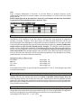
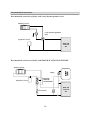
R
WOOD GASIFYING BOILER
ATTACK DP
TECHNICAL MANUAL
ATTACK DP - Wood gasifying boiler
- Assembly, pre-heating and training of the attendance is perfomed by an assembly technician
trained by the manufacturer, who also fills in a document on the installation of the boiler
-During wood gasifying, tar and condensates (acids) are created in the fuel bin. Therefore
behind the boiler the mixing appliance regumat or temperature-responsive valve must be
installed, to keep the minimum temperature of return water of 65°C into the boiler.
- Operation temperature of water in the boiler must be of 80-90°C.
- The boiler must not be permanently operated with the output lower than 50%.
- When a circulation pump is used, it must be controlled by a separated thermostat in order to
keep the prescribed minimum temperature of return water.
- Ecological operation of the boiler is during nominal output.
- We recommend to install the boiler with storage reservoirs and Regumat which guarantees
economy in fuel in 20 až 30% and longer service life of the boiler as well as comfortable
attendance.
- If the boiler cannot be attached to the accumulation, we recommend to connect it at least
with one equalisation basin with the volume of about 25l for 1 kW of the boiler output.
- During the mode with decreased output (summer mode and water heating) it is necessary to
star t burning daily.
- Fuel must be used only dried of 12 - 20% moisture content (with a higher moisture content
of fuel the output of boiler decreases and its consumption increases)
- The choice of the right boiler size, that is its heating output, is a very important condition for
economic operation and right function of the boiler. The boiler must be chosen so that its
nominal output responds to heat loss of the heated object.
The guarantee does not apply for the boiler if:
- it is operated with wood exceeding 20% moisture content or with fuel not prescribed by
the manufacturer.
- If a proper mixing appliance Regumat is not installed in the system, whích provides for
return water the temperature of 65°C.
- a functional thermostatic valve (WATTS STS20) is not installed on the cooling circuit
of boiler and connected to the source of cooling water.
2
Content:
2. Important
3 Content
4 Introduction, general description
5 Technical parameters
6 Dimensions of boilers
7,8 Control board of ATTACK DP STANDARD, PROFI
9 Purpose of use, technical paramaters, operational rules
10 Warning
11 Technical description of DP PROFI
12 Overheating of the boiler, the ways of regulation, displaying faults
13 Maintenance of heating system, Prescribed fuel
14 Chimney, exhaust pipe, connecting boiler to the mains
15 Protection of boiler against corrosion
16 Recommended connection
17 Protection of boiler against overheating
18 Defects and their remedy
19 Possible faults and the means of their elimination
20 Scheme of dependency of resistance on the temperature of heating water by the
thermal probe ( DP PROFI )
21-22 Electrical schemes of boiler connections ATTACK DP
3
Introduction:
Dear customer,
Thank you for confidence that you showed us by purchasing our product - ATTACK wood
gasifying boiler. We wish you long and reliable operation. Proper attendance of the boiler is one
of the conditions for reliable and right operation, so please read this instruction for use
carefully. The manual is written in the way to respect the right operation of the boiler in
central heating system.
The conditions of right operation of the boiler:
- to choose the right type and output of the boiler
- impeccable putting into operation
- sensitive attendance
- regular technical maintenance
- reliable service
General description:
ATTACK DP wood gasifying boiler is designed for economic and ecological heating of
family houses, bungalows, small plants, workshops and similar objects.
Specified fuel for ATTACK DP boilers is dry wood, e.g. logs of lengths, depending on the type
of boiler. The wood gasifying boiler is the holder of
101 5 certificate.
Description of ATTACK DP brand:
ATTACK D P 25
35
45
75
Wood gasifying boiler
Standard
Boiler output
Version
ATTACK D P 25
35
45
75
Wood gasifying boiler
Profi
Boiler output
Version
4
Technical parameters:
Type of boiler
DP25
DP 35
DP45
DP75
Boiler output (verzia STANDARD)
kW
16-25
22-35
29-45
48-75
Output range (verzia PROFI)
Heating surface
kW
m2
10-25
2,30
14-35
2,70
18-45
3,10
30-75
5,20
Feed hopper capacity
dm3
105
145
185
350
Dimension of feeding openning
Specified chimney
mm
Pa
235x445
25
235x445
25
235x445
25
294x544
25
Max. working water overpressure
Boiler weight
kPa
kg
250
350
250
390
250
420
250
650
Diameter of flue connection
mm
152
152
152
219
Boiler height
Boiler width
mm
mm
1080
580
1080
580
1080
580
1320
750
Boiler depth
Shielding of electric parts
mm
IP
1050
21
1150
21
1265
21
1600
21
Electrical input
Boiler efficiency
W
%
45
86
45
86
45
86
45
86
CO emision class
3
Temp. of flue gas in nominal output
°C
220
220
220
220
Flow of flue gas in nominal output
kg/s
0,015
0,018
0,021
0,045
65
65
65
65
Maximum noise level
Specified fuel
Average fuel consumption
Consumption for season
dB
Dry wood of 15-17 Mj/kg-1 calorificvalue,water content
min. 12% - max. 20% diameter 80-150mm
-1
kgh
Voltage
Range of temperature
of heating water
Range of room temperature
( PROFI version)
Current carrying capacity
of boiler regulator contacts (PROFI version)
10,5
13,5
22,5
3
Max. length of logs / Depth of combustion chamber mm
Burning time in nominal output
Water volume in boiler
Min. volume of equalisation basin
7,5
hod.
l
l
550/580
3
65
500
1kW = 1m
650/680 750/780
3
78
625
3
92
750
V/Hz
°C
230/50
65-90
°C
10-27
V/A
230 / 1,5
Specified min.temperature of returnable water in operation is 65°C.
Specified temperature of water during operation in the boiler is 80-90°C.
5
1000/1100
3
160
1500
Dimensions of ATTACK DP boilers
152
80
G 1/2"
225mm (DP25,35,45) / 290mm (DP75)
80mm (DP25,35,45) / 100mm (DP75)
depth
width
DP25
DP35
DP45
DP7 5
C.H.flow connection
G6/4"
G6/4"
G2"
G2"
C.H.return connection
G6/4"
G6/4"
G2"
G2"
ATTACK ®
6
2
9, 10,11,12,13,14,15,22 21
15
16
17
18
5
3
20
7
4
19
1
8
1. Boiler body
2. Control board
3. Feeding door
4. Ash door
5. Sucking fan
6. Flue
7. Heatproof shaped piece - jet
8. Heatproof shaped piece - ash pan
9 Boiler thermostat
10. Reset
11. Flue gas thermostat
17
12. Control thermostat of ventilator
13. Switch
14. Thermometer
15. Regulator of output
16. Cooling down circuit against overheating of water in boiler
17. Cover of cleaning hole
18. C.H.flow connection
19. C.H.return connection
20. Control door
21. Pull rod of chimney flap
22. Boiler regulator (PROFI version)
6
Control board
ATTACK DP Standard
Wood gasifying boiler "ATTACK DP Standard" is controlled by a boiler and flue gas thermostat.
1. Reset
2. Fuse
3. Main switch
4. Flue gas thermostat
5. Boiler thermostat
6. Thermometer
7. Pull rod control
Description:
1. Reset - protection of the boiler against overheating (in case the temperature is higher than
110 degrees C, the boiler is disconnected from the power net)
2. Fuse - protection of the boiler against short circuit
3. Main switch - switching on of the boiler,switching off if necessary
4. Flue gas thermostat - when the temperature of flue gas decreases under set up value, the
fan is switched off
5. Boiler thermostat - serves for setting up maximum temperature of water in the boiler (after
exceeding set up temperature the fan is switched off and the
boiler works with minimum output. After decreasing set up temperature
the fan is switched on again and the boiler works with maximum
output.
6. Thermometer - indicates outlet temperature of water from the boiler
7. Pull rod control - serves for opening and closing of fuel cut-off flap
7
ATTACK DP Profi
The asset of Profi version of ATTACK DP boilers comparing with Standard version is in more
comfortable service and the possibility of heat output modulation and addition of control elements.
The boiler temperature is kept at the level set by the user, by setting up number of revolutions of the
flue gas fan. ATTACK PROFI boiler regulator measures the temperature of water in the boiler
continuously and depicts its value on the display, controlling the pump of central heating at the same
time. There is a possibility to connect a room thermostat to the boiler regulator. The room thermostat
provides thorough regulation of temperature of heated rooms. The control of drive of the four-way
mixing valve is possible as well.
1
9
1 - Main switch
7 - Control light of circulating pump operation
2 - Display showing the
boiler temperature
8 - Control light of lack of fuel
3 - Control light of
burning up process
9 - Turning button of room
thermostat
4 - Control light of boiler overheating
5 - Control light of
room thermostat
10 - TEST button (by pressing the button
the temperature set up by the turning button 6.
appears and at the same time flue gas
fan switches off for a moment)
6 - Turning button of boiler
thermostat
Backward view of electronic regulator:
Setting of post purge time of fan after reaching set up temperature of heating water
Setting of flue gas
fan speed during
burning up mode
Fuse
2A
Connecting of
mixing valve
(12 V)
Connecting of room temperature sensor or thermostat
8
2
8
3
4
5
7
10
6
Purpose of use
Ecological hot-water boiler Attack DP is designed for heating of family houses and similar
objects. The boiler is designed for burning wood only. Any dry wood can be used for
burning, mainly logs. Also wood of bigger diameter, blocks, can be used, which reduces
nominal output but prolongs burning time. The boiler cannot be used for burning filedust and
small wooden debris. This can be burnt only in small amount together with logs (max. 10%).
Due to its large feed hopper you can avoid the most demandable operation of preparation and
cutting the wood into smaller pieces.
Location of the boilers in living spaces (including halls) is inadmissible!
Technical description
The boiler is designed for combustion of wood on the principle of wood gasifying using a
flue gas fan sucking flue gas from the boiler.
The body of the boiler is a weldment of metal steel plates of 6 mm thickness. It includes a
feed hopper with a heatproof shaped piece that has an oblong opening for transition of flue
gas and gas. Under it in the after-combustion space there is an ash pan. In the rear part of the
boiler there is vertical flue channel with a fuel cut-off flap in the upper part. There is also a
suction branch for connection to the flue.
In the front wall in the upper part there is a feeding door and in the bottom part there is an
ash door.In the front part of the upper cover there is a pull rod of fuel cut-off flap. The body
of the boiler is from the outside insulated by mineral fleece put under the covers of outside
jacket. In the upper part of the boiler there is a control board for electromechanical
regulation.
In the rear part of the boiler there is a channel for inlet of primary and secondary air with a
regulation flap where the air is heated to a high temperature.
Description:- STANDARD version
- Thermometer indicates outlet temperature of the boiler
- If it is necessary, the boiler can be switched off by main switch
- Electric circuit is protected by a fuse
- Fan can be switched off by a flue thermostat after burning down fuel.
ATTENTION! For heating up, set this thermostat to 0°C. After fuel starts burning, set the
flue thermostat to "Operation". If the temperature of flue gas drops under set up temperature,
the flue thermostat is switched off. If you want the fan start again, you have to set up a lower
temperature.The optimum condition for operation must be tried.
- Regulation thermostat controls the operation of the fan by the outlet temperature of water
from the boiler.
- Safety non-returnable thermostat serves as protection against overheating in case of
breakdown of the regulation thermostat or as signalization device for overcoming safety
temperature. After overcoming the temperature it is necessary to press it.
Operation rules
Preparing the boiler for operation
Before putting the boiler into operation make sure whether the system is filled with water and
deareated. The boiler can be operated only in accordance with these instructions in order to
work properly.It can be operated only by an adult. When installing the boiler, lay something
under the rear part to elevate it in 10 mm for better flushing and deareating.
9
Warning
After the first heating up, there can be condensation and condensate may leak. This is not a defect
Condensation disappears after longer heating. When burning smaller wooden waste it is necessary to
check the temperature of flue gas which must not overcome 320°C. Otherwise the fan can be
damaged. Creation of tar and condensate in the feed hopper is a phenomenon accompanying wood
gasifying.
If the boiler was out of order for a longer time (switched off,broke down), it is necessary to use
extreme caution when putting into operation again. In not working boiler , the pump can be blocked,
water can leak or the boiler could get frost in winter.
Heating up and operation
Before burning the fuel open the fuel cut-off flap pull the pull rod of the flap and set the flue
thermostat to 0°C. Through the upper door put dry wood chips on the heatproof shaped piece
perpendicularly to the channel to leave 2-4 cm gap between the fuel and channel for transition of flue
gas. Put paper or wood wool on the chips, then chips again and a bigger amount of dry wood. After
burning the fuel switch on the fan and close the fuel cut-off flap.On the thermoregulation valve set the
demanded temperature of water (80- 90°C). After proper start fill in the whole fuel bin and set up the
fuel thermostat into operation position.
CAUTION: During the operation the pull rod of fuel cut-off flap must be shifted in otherwise the fan
can be damaged..
To gasify wood, there must be a reduction zone in the boiler (a layer of charcoal on the ceramic shaped
piece in the feed hopper). The layer can be created by combustion of dry wood of proper size. When
wet wood is burned, the boiler is not working as a gasifying boiler and the consumption of wood
rises, output is lower than demanded and the service life of boiler as well as that of flue is shortened.
If the draft is as specified, the boiler works up to 70% of output even without a fan.
Electromechanical output regulation
Output regulation is conducted with a flap on the rear side of the boiler wich is controlled by a
thermoregulation valve. The valve opens or closes the flap automaticly by set up outlet temperature
(80 - 90°C) of water. Pay special attention to setting up the thermoregulator as this except of
regulation has another important function - protection the boiler against overheating. For setting
up follow the instructions for aseembly and set up of the regulator.Check the protection against
overheating by verifying the function of regulator with 90°C water. For this temperature the
regulation flap must be almost closed. Set up of the regulator must be tested. The position of the
regulation flap can be watched from the back side of the fan. With the boiler thermostat located on the
panel of the boiler you can control the fan by outlet temperature of water. The temperature on the
regulation thermostat should by in 5°C lower than the one on the thermoregulator. On the panel there
is also a flue thermostat serving to stop the fan after burning out of the fuel. For heating up, set it up to
0°C. After proper heating up set it up to operation position so that the fan is working and is not
stopped until burning out of fuel. The optimum position of the flue thermostat must be watched by the
kind of fuel, draft and other conditions. Check the temperature of outlet water on the
thermomanometer. On the panel there is also a safety non-returnable thermostat.
Refueling
For refueling first open the fuel cut-off flap by the pull rod, do not stop the ventilator. Wait for some
10 seconds, then slowly open the feeding door so as accumulated flue gas can be draught to the flue.
During heating keep the feed hopper always full. To prevent smoke, stoke other fuel only after the
original charge is burnt out at least to 1/3 of the content. Then cover live coal with a broad log and fill
in as usually. The fuel must not be pressed over the jet as this could cause extingiushing the fire.
CAUTION! During operation the pull rod of fuel cut-off flap must be shifted in, otherwise the fan
can be damaged.
10
Technical description of ATTACK DP PROFI:
During the operation, the display is showing the current temperature of outlet heating water.
Speed of the fan are controlled in this way:
- if during burning up proces the boiler temperature is lower than 45 °C, the fan works with the
output set up by the turning of burning up button situated in rear side of regulator in the range of
40 - 100 %. (on the display you can see r4 = 40% do r9 = 90 %, rF=100%), for boiler
temperature higher than 45°C the fan works up to 100%.
- if the temperature of heating water during the operation is more than 10°C lower than the one
set up by the turning button, the fan works in 100 % output.
- if the temperature of heating water is lower than 10°C from the temperature set up by the
turning button of the boiler thermostat, the regulator decreases the output of ventilator according
to the difference between these temperatures but only to the output not lower than 40%.
- if the boiler temperature is higher or equal to the temperature set up by the turning button of the
boiler thermostat, the fan switches off.
- the ventilator switches on again after decreasing the boiler temperature in o 5°C comparing to
the set up temperature.
The regulation of boiler ensures that the pump for central heating switches off when the
temperature of oulet water in the boiler decreases under 60°C. The pump switches on again by the
temperature higher than 65°C.
To prevent explosion of accumulated gas during ignition, the boiler regulator ensures purging of
gas in the boiler in 5 seconds and then each minute until 9 minutes according to the position of
the turning post-purge time button in the rear part of the regulator. During the set up there is
always information on the display which lasts 2 seconds (P1,...., P9, P-). In case you do not wish
purging of gas in the boiler, it is necessary to set up (P--)..
To make the process of burning up the boiler stable, there is a burning up system installed in the
regulator. After plugging in or stopping the alarm the regulator is set up to the process of burning up
and this mode is signalled by a shining dot on the display. The process of burning up is finished when
the dot stops shinig and the boiler temperature reaches the value set up by the thermostat. In case the
temperature in the boiler does not exceed 65 °C in 2 hours of burning up time,the regulator stops the
waste-gas ventilator and switches on the control light - missing fuel.
In the time of burning out the boiler when the temperature falls under 65 °C and this condition lasts
for more than 30 minutes, the regulator stops the flue-gas fan and the control light of missing fuel
shines on.
Missing fuel
When the temperature of heating water in the boiler falls under 65 °C and this condition lasts for
more than 30 minutes, the regulator stops the flue-gas fan and the control light of missing fuel
shines on. If in the burning up process the boiler temperature does not raise to more than 65°C,
missing fuel will be shining on the display after 2 hours. To start the regulation again, it is
necessary to:
- refuel the boiler;
- burn the boiler up
- turn the turning button of the boiler thermostat into the maximum left position and thus stop
the alarm
-wait until the control light of missing fuel flickers,
- by turning button of the boiler thermostat set up the required temperature of the boiler and the
regulator starts the process of burning up
11
Overheating of the boiler
If the temperature of the boiler raises to more than 95 °C, the regulator stops the flue-gas
fan and the control light of boiler overheating shines on. For new start it is necessary to:
- wait until the boiler temperature falls
- remove the cause of boiler overheating (e.g. refill missing water into the central
heating circuit)
Warning! Water can be refilled only after the boiler temperature falls under 40°C.
- Turn the button of the boiler thermostat into the maximum left position ad thus stop
the alarm
- wait until the control light of boiler overheating starts flickering;
- to start the regulator again, set up the required temperature of the boiler by the turning
button of the thermostat;
If the temperature falls under 60 °C, the regulator comes into the burning up mode.
The ways of boiler regulation
The boiler enables regulation of room temperature as well as connecting the sensor of room
temperature. If the room temperature is lower than the set up one, the control light near the
button of thermostat shines on, which means that the boiler must keep the set up temperature.
After reaching the required temperature the control light switchces off, the circuit pump of
central heating switches off and the boiler starts burning at the temperature of 65 °C.
For the regulation by room temperature it is possible to connect with the terminals for the
sensor of room temperature any room thermostat that can be programmable.In this case the
turning button of the room thermostat is not working.
If you do not wish to use the room thermostat nor the room sensor, the inlet terminals must be
short-circuited. In this case only the boiler thermostat is working.
To the boiler regulator can be also connected a mixing valve with an 12V electric drive. (This
system is not delivered with the boiler).
Displaying faults:
The boiler regulator constantly verifies the functions of internal systems and of the sensor of
boiler temperature. After finding out the defect, the regulator switches off the flue-gas fan, the
central heating pump and at the same time the defect shows on the display. In the case of failure
it is necessary to switch the boiler off by the main switch. Continuous operation of the central
heating pump must be assured by plugging into the mains. Fuel must be burnt thoroughly and
the contract service company contacted.
If E1 fault appears on the display, it means the damage of the sensor of boiler temperature.
12
Permanent-heat operation
Permanent-heat operation of the boiler means fire can be kept during the night without heating up daily, but only
in winter. This way of operation shortens the service life of the boiler. For permanent-heat operation prepare the
boiler this way:
- Put a few bigger logs (4-6)on theglowing layer
- Get themixing valve ready.After closing the valve the temperature of water rises to 80- 90°C.
- Regulation flap controlled by the thermoregulator is closedautomaticly and the fanis switched off.
In the boiler prepared like this burning is kept for more than 12 hours. During permanent-heat operation the
temperature of water in the boiler is 80 - 90°C.
Cleaningthe boiler
The boiler must be cleaned regularly and properly every 3-5 days because ash settled down in the feed
hopper together with condensates and tar decreases output and service time of the boiler and isolates heatexchanging surface. When there is too much ash, there is not enough space for burning out of fuel and a holder of
ceramic jet as well as the whole boiler can be damaged. When cleaning the boiler, firstly turn the ventilator on,
open the feeding door and wipe the ash through a slot into bottom space. Leave long unburnt logs in the feed
hopper. Open the upper cleaning cover and clean inside with a brush. After opening the bottom cleaning hole take
ash and soot out. After opening the bottom door clean the bottom space. Cleaning interval depends on the quality of
wood (moisture content), heating intensity, draft of the flue and other circumstances. We recommend to clean the
boiler once a week. Do not pull the fireclay shaped piece out when cleaning. Once a year minimally clean the
moving wheel of the fan and check through the cleaning hole fouling of regulation of primary and secondary air
flowing into feed chamber and clean with a screwdriver if necessary. It influences the output and quality of
burning. WARNING - Regular and proper cleaning isimportantfor permanent output and service life of the boiler.
In case of insufficient cleaning the boiler can be damaged and guarantee expires.
Maintenanceof heating system and boiler
At least once in fortnight check or fill up water in the heating system. If the boiler is out of operationduring winter,
water can be frost in the system. Therefore it is better to discharge water of the system or fill in with antifreeze
agent.Otherwise discharge water only in critical situations and for the shortest time possible. After heating season
is finished, clean the boiler thoroughly, replace damaged parts. Twice a year clean the moving wheel of the
ventilator and its air chamber.
Changing the packing cordof the door
Dismantle the old packing cord with a screwdriver and clean the rabbet where it was placed. Take the new packing
cord and put its begining on the horizontal parts of the rabbet. With your hand or light knock of the hammer press it
into the rabbet on the circumference of the door.
Adjustment of hinges
After some time the packing cord in the door gets deformed. To repack the door, it is necessary to change the
position of the door. The position is changed by tightening the hinges of thedoor. Feeding door and bottomdoor are
joined to the body with two hinges which are attached to the door with a long pin. If we want to change the
adjustmnent of hinges, it is necessary to remove the pin and screw the hinge by turning it. Fit the door on and insert
thepin into the hinge.
Exchange of the nozzle body
The body of nozzle is placed in the boiler body in a nozzle holder. In the lower part is the nozzle body sealed by
boiler lute and in the upper part by a packing cord. When exchanging the nozzle, remove the packing cord from the
rabbet by a screwdriver. Remove the nozzle body and clean the holder thoroughly from the tar and old lute. On the
cleaned surface put the nozzle body insulation. Take the nozzle and put it on the holder so that the shorter wall was
in the rear part of the boiler pushed to the stop. The lateral clearance must be the same. Take the new set of packing
cords of the nozzles and with a light knock press it into the gap so as to be at the same level with the nozzle.
Setting of theboiler combustion
Setting of the boiler combustion is executing through the regulations flaps of the primary and secondary air.
Boilers are from the production set for the most optimal burning conditions in term of the emissions and the
tempertature of exhaust gas.Setting can be executed only by producer or by trained serviceman.
The most optimal setting of the regulation flaps:
flap of the primary air:
DP25 totally closed /backstop/
DP35 totally closed /backstop/
DP45 totally closed /backstop/
DP75 backstop +5 mm
flap of the secondary air:
DP25 backstop +2 mm
DP35 backstop +2 mm
DP45 backstop +4 mm
DP75 backstop +4 mm
Prescribed fuel
Specified fuel is dried cut wood and logs of 80-150mm diameter, with min. 12% and max. 20% moisture content
-1
andcalorific value of 15 - 17MJkg . It is alsopossible to burn big pieces of wooden waste with thicklogs.
13
Note
Logs of bigger dimensions is necessary to cut into halves or quarters (because of the
requirement of operation to nominal output). You can burn hard as well as soft wood. Wood
must be dried!
Boiler output depends on the moisture content of wood. Output and function of the boiler
is guaranteed for maximum moisture content of 20%.
Chimney
Attachment of the appliance to the flue must be always done with approval of authorized
chimney-sweeping company. There must always be sufficient draft in the flue and flue gas
must be draught to the atmosphere in all possible operation conditions. For the right operation
of the boiler the independent flue must be dimensioned in the right way, because combustion,
output and service life of boiler depends on the draught. The draught is influenced by the
section of flue, height and roughness of the internal wall. Into the flue where the boiler is
attached, no other appliance can be attached. The flue diameter must not be smaller than the
outlet on the boiler. Flue draught must have the specified values. But it must not be too high so
as not to decrease the efficiency of boiler and interrupt burning. If the draught is too strong,
install a throttle valve between the flue and boiler..
Informative values of flue section:
20 x 20cm
O 20cm
15 x 15cm
O 16cm
min.height 7m
min. height 8m
min. height 11m
min. height 12m
Exact dimensions of flue are specified by the standard STN 73 42 10. Flue draught is specified
in technical parameters.
Exhaust pipe
Exhaust pipe must have the outlet into the chimney.If the boiler can not be attached to the
chimney directly, the exhaust pipe must be as short as possible and not longer than 1m
without heating surface and it must rise to the flue. Exhaust pipes must be tight and resistant
against flue gas leakage and cleanable from inside. Exhaust pipes must not come through home
and utility spaces and the internal section of the exhaust pipe must not be narrowing to the flue.
Using of bents is not suitable.
Connecting the boiler to the mains net
The boiler is connected to the mains of 230 V, 50 Hz by a supply cord and plug. The voltage is of
M type and when replaced, the same type must be used by a service oragnization.The appliance
must be located in such a way that the plug was within the reach of the attendance.
(according to STN EN 60 335-1 +A11:1997).
14
Attachment of regulation and control elements
The boiler is delivered to a consumer equipped with basic regulation and control elements.
Attachment of these elements is indicated on the chart of connection. We recommend to extend
the regulation of boiler with other regulation elements which enable more comfortable and
economic operation. Each pump in the system must be controlled by an individual thermostat
so as the boiler was not undercooled on the inlet of returnable water under 65°C.
Attachment of these elements can be suggested by a designer due to specific conditions of the
heating system. Electric installation together with the proper equipment of the boiler must by
done by a specialist in compliance with valid standards. The basic version of boiler (Standard)
does not have a thermostat for pump built.
Protection of boiler against corrosion
Suitable solution to this problem is mixing appliance (Regumat ATTACK-OVENTROP) or a
thermoregulation valve which enables separated boiler and heating circuit. This way you can
prevent undercooling of boiler under 65°C and also decrease condensation of steam, acids and
tars in the feed hopper. With a flap of three-way valve you can regulate the temperature of
heating water independently on temperature of water in the boiler. Water in the boiler must be
permanently of 80-90°C.
Standards for design and assembly of boilers:
Section cross boiler - combustion chamber
STN EN 303-5 - Heating boilers using solid fuel
STN 73 42 10 - Production of flues and exhaust pipes
STN 92 03 00 - Fire safety of local appliances
STN EN 60 335-1 +A11 - Safety of domestic electrical appliances
STN 06 10 00 - Local appliances of solid, liquid and gaseous fuels
Installation and exchange of the heatproof shaped pieces:
The back part of the ash pan pos.1 insert into the lower chamber
and push to stop to the back plate. Insert the front part of the ash
pan pos.2 and push to stop to the back part of the ash pan.
On the ash pan put the super-structure of ash pan pos.3 and push
it to stop to the rear. The ash pan should be situated in the centre
line of boiler at the front sight.
By the exchange of the damaged jet pos.4 or cube pos. 5 follow
the next: Jet and cube /cube only by DP35 and DP45/ take out
after the elimination of gaskets. Then insert new jet eventually
cube and backwards seal up with gasket. If it is necessary, gaskets
also change with new. The jet is inserted with the sign, which is
situated on the lower part of the jet into the back part of the boiler.
15
Recommended connections
Recommended connection of boiler with 4-way thermoregulation valve
Heating system
4-way thermoregulation
valve
Expansion vessel
BOILER
ATTACK
DP
Recommended connection of boiler with REGUMAT ATTACK-OVENTROP
Heating system
Pump
Expansion vessel
Regumat
ATTACK-OVENTROP
Check valve
16
BOILER
ATTACK
DP
Recommended connection of boiler with accumulation tank
D.H.W
Tank
Heating
system
Regumat
ATTACK-OVENTROP
ACCUMULATION
TANK
BOILER
ATTACK
DP
Expansion vessel
Boiler has to be operated with the nominal output. In case of the warmth taking by the output, which is
lower than the nominal, it is necessary to connect the boiler with the accumulation tank with volume of
min. 460 l (STN EN 303-5, clause 4.2.5 ).
Protection and usefull life extention of the boiler
1. ATTACK Oventrop keeps the temperature of return heating water coming to the boiler on
65 °C. Temperature of return heating water under 60°C causes the condensation of steams,
acids and tars in the feed chamber and it is the reason of the boiler usefull life shortening.
1
2
Technical parameters:
Clarity DN25
Max.pressure 10 bar
Max.temperature 120°C
Value kvs 3,9
3
4
ATTACK Oventrop consists of three-way mixing valve, pump Wilo, 2 thermometers,
thermoregulation valve, thermostatic head, by-pass, distance unit and isolation. The
adventage of this solution consists in compactness, simple attendance and guaranteed
protection of boiler heating exchanger.
ATTACK Oventrop for boilers:
Order code:
ATTACK DP25,DP35, DP45, DP75
DPP25003
17
2. Connection with threeway thermoregulation valve
Operational principle is the same as the connection with ATTACK Oventrop regulation
system. When the temperature is higher that 65°C the thermoregulation valve opens the
circuit in heating system. When the temperature is lower than 65°C makes this circuit closed
and the boiler works in the short boiler circuit. This appliance keeps the return heating water
comming to the boiler at the min. temperature of 65°C.
Recommended threeway regulation valve:
For Boiler:
Type:
Order code:
ATTACK DP25, DP35
DN32
DPP25004
ATTACK DP45, DP75
DN50
DPP45001
3. Connection with accumulation tank
Connection system consists in heating up of water in accumulation tanks and the warmth is
gradually taking away from the tanks according to the request from the heating system. By the
operation with several heating ups at full performance, accumulation tanks will be heated for
the temperature of 90-100°C. Heating with accumulation tanks in connection with the
ATTACK DP boilers bring more advantages.. Among the main advantages belong
enlargement of the boiler life and in the end result also lower consumption of fuel.
Recommended volumes of accumulation tanks according to boiler output:
DP25 - 1500 - 2000 l
DP35 - 2000 - 2500 l
DP45 - 2500 - 3000 l
DP75 - 4000 - 4500 l
Protection of the boiler against overheating
CAUTION: Cooling circuit against overheating
must not be used by STN EN 303-5
for other use than protection against overheating.
STS 20
Water supply
From water piping
Pressure 2-6 bar
10 - 15°C
ODPAD
STS 20 valve which has a sensor placed in the rear
part of the boiler protects the boiler against
overheating. If the temperature of water in the
boiler overcomes 95°C, the valve lets water into
a cooling circuit which overtakes excessing heat
and discharges it into the drain.
Instructions for liquidation of the product after its lifetime
The product should be liquidated by selling to a scrap-material dealer or to a dump managed
by a local authority.
Liquidation of wrapping
.The wrapping should be liquidated by selling to a scrap-material dealer or to a dump
managed by a local authority.
18
19
Scheme of dependency of resistance on the temperature of heating water by the thermal probe ( DP PROFI )
Teplota
°C
-55
-50
-40
-30
-20
-10
0
10
20
25
30
40
50
60
70
80
90
100
110
120
125
130
140
150
MIN
951
1000
1105
1218
1338
1467
1603
1748
1901
1980
2057
2217
2383
2557
2737
2924
3118
3318
3523
3722
3815
3901
4049
4153
Odpor
kOhm
980
1030
1135
1247
1367
1495
1630
1772
1922
2000
2080
2245
2417
2597
2785
2980
3182
3392
3607
3817
3915
4008
4166
4280
MAX
1009
1059
1165
1277
1396
1523
1656
1797
1944
2020
2102
2272
2451
2637
2832
3035
3246
3466
3691
3912
4016
4114
4283
4407
20
WIRING DIAGRAM OF GASIFYING BOILER DP25, DP35, DP45, DP75
WITH CAPACITOR
Fluegas
thermostat
Boiler
thermostat
Main switch
5
2
1
4
thermostat
pump 95°C
Fuse
2A/250V
Capacitor
Highlimt
thermostat
WIRING DIAGRAM OF GASIFYING BOILER DP25, DP35, DP45, DP75
"PROFI" WITH CAPACITOR
230V/50Hz
Capacitor
red
RECORD ON PUTTING THE BOILER TO
OPERATION
Data on the customer (llegible)
Production number..............................
Name and surname:
Date of putting to operation................ .........................................
Service organization:
Street: .............................
............................
Post code, town:.
.Stamp, signature
........................................
........................................................ Tel. No. ..........................
Obligatory service examination after the 1st year of operation
Date : .................................... Stamp, signature of service organization. : ................................................
Obligatory service examination after the 2nd year of operation
Date : .................................... Stamp, signature of service organization. : ................................................
Obligatory service examination after the 3 rd year of operation
Date : .................................... Stamp, signature of service organization. : ................................................
DOCUMENT on testing and completness
of ATTACK gasifying boiler
DP25
DP35
DP45
STANDARD
PROFI
DP75
Boiler production No.:
The product delivered with this certificate suits to technical
standards and technical conditions.
The product was manufactured by its drawing design in requested
quality and is approved by SZÚ Brno under the No. of certificate
Technical inspection
In Vrútky, date: .....................................................................................
Stamp and signature of the final inspection: ........................................
The country of delivery of the appliance :
SK CZ AT CH DK ES FI FR GB GR IE IT NL NO PT SE
Producer:
ATTACK, s.r.o.
Dielenská Kružná 5
038 61 Vrútky
SLOVENSKO
Tel:operator
043/ 4003 101
Fax:
043/ 4003 106
Tel./fax: infoline
043/ 4003 104
Tel: service
0905 410 204
E-mail: [email protected]
http: www.attack-sro.sk