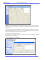
1
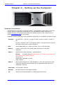
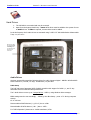
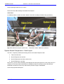
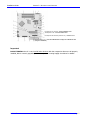
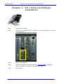
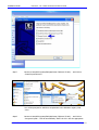
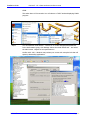
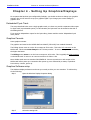
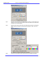
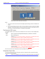
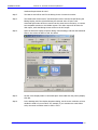
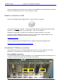
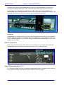
DREAM II
Installation Guide
10 January 2007
Version 1.0
Table of Contents
CHAPTER 1 - INTRODUCTION .......................................................................................3
Purpose of this Manual .........................................................................................................3
System Components ............................................................................................................. 3
CHAPTER 2 - SETTING UP THE COMPUTER ...............................................................4
Hardware requirements ........................................................................................................ 4
Hard Drives ......................................................................................................................... 5
Audio Drives ......................................................................................................................................5
System Board Components / Card Layout............................................................................... 6
Important ..........................................................................................................................................7
CHAPTER 3 - CC-1 CARD AND SOFTWARE INSTALLATION .....................................8
CHAPTER 4 - SETTING UP GRAPHICS/DISPLAYS ....................................................13
Embedded Pyxis Track ........................................................................................................ 13
Graphics Caveats................................................................................................................ 13
Graphics Software setup ..................................................................................................... 13
Positioning the FMC screen ................................................................................................. 15
Independent Pyxis Video..................................................................................................... 15
CHAPTER 5 - CONNECTING COMPONENTS..............................................................18
CC-1 and SX20................................................................................................................... 18
Satellite II connections / USB .............................................................................................. 19
Constellation XT/Anthem connections................................................................................... 19
ExtremeUSB® Connection ................................................................................................................ 19
Station connection.............................................................................................................. 20
Audio Connection from CC-1 ............................................................................................... 20
CHAPTER 6 - SURFACE SETUP ..................................................................................21
CHAPTER 7 – INSTALL CMI (MADI CARD) .................................................................24
Introduction....................................................................................................................... 24
Installation ........................................................................................................................ 24
Connection ...................................................................................................................................... 25
CHAPTER 8 - DREAM II UTILITIES...............................................................................26
Purpose............................................................................................................................. 26
Details............................................................................................................................... 26
Installation Guide
CHAPTER 1 - INTRODUCTION
Chapter 1 - Introduction
Purpose of this Manual
This manual is designed for those who wish to set up a Fairlight DREAM II system for themselves.
Most commonly, DREAM II systems are set up and tested at the Fairlight factory, but it is also possible
to purchase only the factory-made components from FairlightAU Pty. Ltd., and assemble them into a
system with off-the-shelf components.
Technically, setting up a DREAM II system is straightforward, but it does require experience with
computer hardware and software. Anyone who has not performed basic PC builds is advised not to
attempt this. As an example, adding storage devices or circuit boards to a PC, and installing the
necessary drivers and other software, would qualify as the right kind of experience.
In some cases BIOS settings will need to be checked and/or changed. This manual does not explain in
detail how this is done, so anyone attempting assembly of a Fairlight system should seek instructions
from their PC manufacturer.
System Components
A DREAM II system includes the following components:
1. One standard computer.
Fairlight currently supplies and recommends Dell PrecisionTM 390 Workstations. If other computer
brands or types are used, Fairlight cannot guarantee or support them. We do attach a specification,
however, which gives the minimum performance and equipment level required.
2. One CC-1 circuit board
This is the main media processing engine, and is supplied by FairlightAU Pty. Ltd.
3. One SX20 interface box
This box provides clock signals for audio and video synchronisation, plus interfaces to sync signals and
audio I/O. It is supplied by FairlightAU Pty Ltd.
4. One control surface
This could be a Satellite, Station, Constellation or Anthem, and is part of your product’s user interface.
It is supplied by FairlightAU Pty. Ltd.
Your control surface is connected to the computer via USB. For Constellation and Anthem surfaces, we
use a high-speed connection called ExtremeUSB®. See the section called Connecting Components for
details. NOTE: is a registered trade mark of Icron Inc.
5. Software
Fairlight software and firmware is required to run the system. This manual will explain how to install
the software and firmware. Use of the software is explained in the user manual for your product.
6. Optional CMI (MADI) cards
You may purchase MADI cards which each have three input connectors and three output connectors.
Each connector handles 56 digital audio streams at 48 kHz.
7. Optional SX48 boxes
You may purchase SX48 boxes, which provide 48 channels of audio I/O, distributed between analog
and digital formats as you require.
The following sections provide detail about setting up each of these system components.
DREAM II
Page 3
Installation Guide
CHAPTER 2 - SETTING UP THE COMPUTER
Chapter 2 - Setting up the Computer
Hardware requirements
The following list is a description of the Dell PrecisionTM 390 Workstation, shown above. At this time
Fairlight requires that this exact configuration be used with DREAM II products, although it is
expected that new configurations will be tested and released from time to time. Please check our
website www.fairlightau.com for any changes.
WARNING: Computers differing from the specification below may not run DREAM II products correctly.
Processor:
Intel Dual Core – 1.86 GHz (L1 cache: 32.0 Kb, L2 cache: 2.00 Mb, L3 cache: 0
Kb)
Ext.clock: 1066 MHz - Intel® 975X Express chipset. ( Dell offers Dual-Core Intels on
this system ranging from 1.86GHz Æ2.93GHz )
Bios:
Phoenix ROM BIOS PLUS – please use Version 1.10 2.0.8 (24-Sep-2006)
Memory:
2.00 Gb (2 095 124 Kb) 2 X 1024 Mb (DDR2, Synchronous,1 MHz) EEC –
unbuffered.
Video 1:
NVIDIA GeForce 6600 (256.0 Mb) - Leadtek Research.
Drivers:
ForceWare Release 90 (IMPORTANT: do not use a version later than
81 if a Matrox card is used for Video 2)
Version: 91.47
Release Date: September 14, 2006
WHQL Certified
Video 2:
Matrox G550 PCI-Express x1, 32MB, DualHead, 2 x DVI (only required if the Pyxis
Track video option has been purchased, and an independent video output (nonembedded) is required)
Sound card:
No sound card is required
Network:
Broadcom NetXtreme 57xx Gigabit Controller
OS:
Windows XP Professional English 5.1 (build 2600 Service Pack 2)
DREAM II
Page 4
Installation Guide
CHAPTER 2 - SETTING UP THE COMPUTER
Hard Drives
1. The CD-ROM is not needed and may be removed.
2. Apart from the System Hard Drive, 2 extra SATA drives must be added to the system for use
as Audio Drives. If Video is required, an extra drive must be added.
In the Dell system, the 2 Audio Drives are mounted using 2 SATA 3.5" HD Mobile Racks & Removable
Trays. See photo below.
Please note that
the external Dell
trimming does
not permit these
drives to be
removed.
Audio Drives
We have successfully tested the following drives for audio: Western Digital - MODEL: WD1500ADFD
SATA Hard Drive / 150 GB, 1.5 Gb/s, 16 MB Cache, 10,000 RPM.
RAID Setup
The Dell 390 has an Integrated SATA 3.0Gb/s controller with support for RAID 0, 1, and 5. Any
alternative PC must offer the same performance.
The 2 Audio drives are set up as 2 striped drives – RAID 0, using Windows Drive manager.
BIOS settings must be set accordingly … Please go into Bios Setup – press <F2> during computer
startup.
Go to <Drives>
Please enable all SATA devices ( 0,1,2 & 3 ) Set to <ON>
Please disable all PATA devices ( 0 & 1 ) Set to <OFF>
For “SATA Operation” please set to <RAID Autodetect / ATA>
DREAM II
Page 5
Installation Guide
CHAPTER 2 - SETTING UP THE COMPUTER
Smart reporting should be set to <OFF>
Please save these Bios settings and restart the computer.
Video Drive
An Additional drive for Video has been added in the Dell’s secondary hard-drive bay (see below).
Any SATA hard drive may be used for this … 7200 RPM or above. 8Mb cache minimum.
System Board Components / Card Layout
The Dell™ computer provides the following slots for PCI and PCI Express cards:
1. Three PCI card slots
2. One PCI Express x16 card slot
3. One PCI Express x8 card slot (wired as x4)
4. One PCI Express x1 card slot
Note: the x1, x8 etc used in describing a PCI Express card slot (also known as 1-lane, 8-lane etc) is a
measure of how many serial connections are available at that slot. Different cards need different
bandwidth connections to the host, and the slots provide a range of bandwidths.
Here is the proposed card layout:
DREAM II
Page 6
Installation Guide
CHAPTER 2 - SETTING UP THE COMPUTER
PCI-Express x1 card slot –used for Matrox Card
PCI-Express x16 – used for Nvidia Card
PCI-Express x8 card slot (wired as x4) – used for CC-1
PCI card slots (1–3) – used for USB Extreme Card(s) and a Decklink card
(if Pyxis is installed)
Important
DO NOT INSTALL the CC-1 card until all other devices with their respective drivers are all properly
installed, Bios is correctly upgraded, and the computer is running happily. See below for details.
DREAM II
Page 7
Installation Guide
CHAPTER 3 - CC-1 CARD AND SOFTWARE INSTALLATION
C h a p t e r 3 - C C - 1 C a r d a n d S o ft w a r e
Installation
Step1
Shut down the computer.
Step2
Install the CC-1 card into the PCIe ( 4 lane slot ). Use the locking plate to secure the
card into the slot.
Step3
Power on the computer.
Step4
Windows will detect the card as a “default” Æ PCI to PCI Bridge ( Found new
hardware PCI device ) and bring up the installation Wizard:
Step5
Click <Cancel>.
DREAM II
Page 8
Installation Guide
Step6
DREAM II
CHAPTER 3 - CC-1 CARD AND SOFTWARE INSTALLATION
Now install Dream_II_vxxxx_setup.exe (the DREAM II installation software supplied
with your product). Use all default settings. However, when you see the following
page … please untick <Program Crystal>.
Page 9
Installation Guide
Step7
CHAPTER 3 - CC-1 CARD AND SOFTWARE INSTALLATION
Browse to Start/All Programs/Fairlight/Dream II/Dream II Utils/ … and click on
<Install Crystal Drivers>.
You will be prompted to add these components to the Windows registry. Click
<Yes>
Step8
DREAM II
Browse to Start/All Programs/Fairlight/Dream II/Dream II Utils/ … and click on
<Program Crystal>. This will automatically “Flash” the CC-1 with the appropriate
Page 10
Installation Guide
CHAPTER 3 - CC-1 CARD AND SOFTWARE INSTALLATION
CORE.
This takes about 15-20 seconds. You will observe a “DOS” window displaying FLASH
progress.
Step9
Turn off Windows visual effects … Browse to Æ Control Panel/System/Advanced.
In the Performance group, click Settings. Select the Visual Effects tab … and select
the radio button <Adjust for best performance>.
Confirm with <OK>. Windows may redraw your screen with a simpler look that will
speed up demanding applications.
DREAM II
Page 11
Installation Guide
Step 10
CHAPTER 3 - CC-1 CARD AND SOFTWARE INSTALLATION
Only If it is a full and clean install from “scratch” on the PC … There is one more
“manual” operation to do before you launch DRYICE for the first time.
Go to the FTP site and download the file WinSXS.zip.
Use the new DryIce ftp area at ftp.fairlightau.com:
Username=dryice
Password=snowflake
Please extract this file ( keeping the embedded tree structure ) to:
C:\WINDOWS\WinSxS
DREAM II
Page 12
Installation Guide
CHAPTER 4 - SETTING UP GRAPHICS/DISPLAYS
Chapter 4 - Setting Up Graphics/Displays
On a system that has been pre-configured by Fairlight, you should not have to change your graphics
settings. But you will need to set up your graphics again if you change your screen settings or
graphics card.
Embedded Pyxis Track
The setup described below uses a single graphics card, so it does not provide a separate video output
for Pyxis track (a purchasable option). In this situation, the Pyxis track can be viewed at the side of
the Editing Screen.
If you need an independent output for the Pyxis video, please read the section Independent Pyxis
Video, below.
Graphics Caveats
Some graphics caveats:
The graphics card must be the NVIDIA GeForce 6600GT (256.0 Mb) from Leadtek Research.
The Editing Screen must run on the hi-res output at 32 bit color. This is the DVI connector on the
NVidia card. This Screen must always be the “Primary monitor”. It can run at any screen resolution,
the higher the better.
The Mixing screen must run on the low-res output at 16 bit color. This is typically the VGA connector
on the NVidia card. It must run at a screen resolution of 1280 x 1024.
Note: NVidia cards must see monitors ON POWER UP. Connect a monitors to each output of the
NVidia card before power up. Connection after power up, even followed by a restart, is pointless.
Power down, connect, power up.
Graphics Software setup
The Windows display software must be set up correctly to drive your two monitors. To achieve this,
do the following:
Step 1
Open the Windows Display Properties dialog
Step 2
DREAM II
Select the Settings tab
Page 13
Installation Guide
CHAPTER 4 - SETTING UP GRAPHICS/DISPLAYS
Step 3
Select the monitor that will run the Editing Screen (number 1 as shown above) and
make sure it is set as the primary monitor. Select Color quality to 32 bit and screen
resolution to your desired setting.
Step 4
Select the other monitor (which will run the Mixing Screen) and set it to Extend the
display. Select Color quality to 16 bit and screen resolution to 1280 x 1024. See
below.
Step 5
Mouse-over the secondary monitor and note down its coordinates. See below.
DREAM II
Page 14
Installation Guide
CHAPTER 4 - SETTING UP GRAPHICS/DISPLAYS
These numbers will be used in the next section.
Notes:
1. You can move the monitors around in the Display Properties dialog, and their coordinates will
change.
2. If you want the Mixing Screen at the left, it is best to position its monitor at the left in Display
Properties. This will mean that the mouse cursor will move from left to right sensibly over the
two screens. It will also mean that its X-coordinate will be negative.
Positioning the FMC screen
The Fairlight software must be aware of the coordinates of the two screens, in order to display them
correctly.
Step 1
Open C:\Program Files\Fairlight\FMC\Data\System_Variables.txt in WordPad
Step 2
Edit the following lines:
WINDOW_X1,0 (if 1 is the Primary Monitor, otherwise the X coordinate value noted
for the Secondary Monitor in Step 5 of Graphics Software Setup.)
WINDOW_Y1, 0 (if 1 is the Primary Monitor, otherwise the Y coordinate value noted
for the Secondary Monitor in Step 5 of Graphics Software Setup.)
WINDOW_X2, 0 (if 2 is the Primary Monitor, otherwise the Y coordinate value noted
for the Secondary Monitor in Step 5 of Graphics Software Setup.)
WINDOW_Y2, 0 (if 2 is the Primary Monitor, otherwise the Y coordinate value noted
for the Secondary Monitor in Step 5 of Graphics Software Setup.)
SCREEN_NUMBER, 1 or 2 or … (This is the number of the monitor where the Mixing
Screen will be displayed. Enter the number of your secondary monitor)
Note: there are other ways of doing this, but this is probably the easiest.
Independent Pyxis Video
If you have purchased the Pyxis Track option, and wish to output the video to an external monitor,
you will need to do the following:
Step 1
Install an extra graphics card. At this point we insist that the Matrox card specified in
DREAM II
Page 15
Installation Guide
CHAPTER 4 - SETTING UP GRAPHICS/DISPLAYS
Hardware Requirements be used.
Step 2
The Matrox card will be used for the Mixing Screen. Connect its monitor.
Step 3
The NVidia card will be used in “horizontal span mode” with the left half driving the
Editing Display, and the right half driving the external video of Pyxis Track.
Horizontal span mode drives two monitors at the same screen resolution, so connect
two compatible monitors to the NVidia outputs. The video output will be from the
VGA output, while the Editing Screen will be on the DVI output.
Step 4
Open the Windows Display Properties dialog. Select Settings, and then the Advanced
button. Now select the GeForce tab. See below
Step 5
Set the nView Display Mode to Horizontal Span. Select Make this the primary display.
Click OK.
Step 6
In the Settings tab of the Display Properties dialog, set the screen resolution to have
double the width of your monitors. For example, if your monitors are each 1280 x
1024, the screen resolution must be 2560 x 1024.
DREAM II
Page 16
Installation Guide
CHAPTER 4 - SETTING UP GRAPHICS/DISPLAYS
Color quality must be 32 bit.
DREAM II
Page 17
Installation Guide
CHAPTER 5 - CONNECTING COMPONENTS
Ch ap t er 5 - Co n n e c tin g C o m p o n e n ts
CC-1 and SX20
The connection needed between the CC-1 card and the SX20 requires a DVI-I dual link cable –
male to male.
DREAM II
Page 18
Installation Guide
CHAPTER 5 - CONNECTING COMPONENTS
These are relatively easy to find, but in most cases, are not available in stores and need to be ordered.
We have seen cables that are up to 12 feet / 4 Meters in length.
Satellite II connections / USB
The Sat II is equipped with a standard USB 1.1 Type B connector on the back.
This can be used directly if needed … The max cable length between a USB computer and this USB
interface is 5 meters (16.5 feet). If you need longer … Here is our suggestion.
USB Ranger 110/410 pair - this allows you to extend your USB to 100meters Æ from Icron.
A cheaper solution is USB Rover 1650, also from Icron., together with a standard USB hub. This
allows you to extend to 50 meters, minus 10 meters per hub.
http://www.icron.com/
This is the technology that we already license from ICRON to make the ExtremeUSB® card.
http://www.icron.com/products/usb/usb_products.php
Constellation XT/Anthem connections
You will need to fit one or more “ExtremeUSB® card(s)” into one or more of the PCI slots of the
DREAM II PC. CAUTION: do not use the PCIe slots – only the old-style PCI slots.
ExtremeUSB® Connection
Your ExtremeUSB® cable is provided by Fairlight. It is a standard Ethernet cable terminated by RJ-45
connectors. At the PC end, plug it into the connector shown below.
DREAM II
Page 19
Installation Guide
CHAPTER 5 - CONNECTING COMPONENTS
Note: this picture shows 3 ExtremeUSB® cards, as used in a 7-bay Constellation. In cases where
more than one ExtremeUSB® card is used, it does not matter which cable goes into which card.
If your system is a ConstellationXT or Anthem, the surface will be open during installation. The
ExtremeUSB® cable is normally passed up one leg of the console, after coming through the floor, and
should then be connected to the RJ-45 connector on the BMIX002A circuit board.
Rear view of the BMIX002A circuit board, showing the RJ-45 connector at the right.
Information
ExtremeUSB® is a Fairlight method of carrying many USB signals down one cable. It uses a standard
Ethernet cable, and connects to a dedicated card in your DREAM II PC. If your DREAM II system is a
5-bay Constellation/Anthem, your PC will be configured with two ExtremeUSB® cards, and you will be
supplied with two cables.
Station connection
Station also uses ExtremeUSB®. One interface card is needed in the PC. Plug the other end of the
ExtremeUSB® cable into the RJ-45 connector at the rear of the console (see below).
Audio Connection from CC-1
CC-1 contains two BNC connectors, providing a standard MADI stream of 56 inputs and 56 outputs at
48 kHz (half this number at 96 kHz). The upper connector carries the outputs.
DREAM II
Page 20
Installation Guide
CHAPTER 6 - SURFACE SETUP
Chapter 6 - Surface Setup
Every DREAM II system comes with a control surface. The controller consists of one or more “panels”.
For example, a Satellite has only one panel (named SatellitePanel2), while a Constellation has meter
panels, fader panels, Central Assign panels, and more.
It is necessary to ensure that the software “knows” what panels are connected, so that it can address
all the controls correctly. The procedure below explains how to do this.
Step 1
Browse to: Start/All Programs/Fairlight/FMC/FMC Utils/Surface Manager
Step 2
Launch the application.
This is where you can set up your appropriate panels and surface types. The screen
will show the panels that are currently connected to the system.
Step 3
Click <Edit-Config> … to start setting up your panels and surface type.
Step 4
Click <Add Panel>.
DREAM II
Page 21
Installation Guide
DREAM II
CHAPTER 6 - SURFACE SETUP
Page 22
Installation Guide
CHAPTER 6 - SURFACE SETUP
Please note that for Satellite II … you should use Console type “Constellation” /
Panel 1 / and “type” SatellitePanel2 … as seen above. If you see that the
firmware for this Panel is “older’ than 4,2.06 ( or if you get a firmware error ) please
highlight the panel and <Reprogram> using the dedicated button. You can calibrate
“as usual” <Shift-PauseBreak-C> once the application is up and running.
DREAM II
Page 23
Installation Guide
CHAPTER 7 – INSTALL CMI (MADI CARD)
C h a p t e r 7 – I n s ta l l C M I ( M A D I C a r d )
Introduction
The CMI card is a three-stream MADI interface card that is optional in DREAM II systems.
Each stream supports 56 inputs and 56 outputs of digital audio at 48 kHz. When operating at 96 kHz
the number of channels is halved.
Installation
Step 1
The CMI card does not connect to the PC motherboard, so it can be placed in any position
where there is room for mounting.
It is held firm using the same type of Locking Plate as the CC-1 card. Place the spring washer
and hexagonal nut on the second BNC connector from the bottom.
Step 2
Connect a standard disk drive power lead to its power socket.
DREAM II
Page 24
Installation Guide
Step 3
CHAPTER 7 – INSTALL CMI (MADI CARD)
Connect three SATA cables from the CMI board to the CC-1, keeping the numbering aligned.
The three SATA ports on the CMI card are shown here. They should be connected to the ports
of the same number on the CC-1 card, shown below.
Step 4
There is no software setup for the CMI card. Its MADI ports will appear in the mixer
automatically.
Connection
The three MADI streams are arranged as IN/OUT pairs, with the upper BNC connector of each pair
being the outputs.
DREAM II
Page 25
Installation Guide
CHAPTER 8 - DREAM II UTILITIES
Ch ap t er 8 - D R E A M II U t ilitie s
Purpose
This Chapter is for Service Technicians
Details
There is a folder here Æ C:\Program Files\Fairlight\DreamII Utilities\; This folder contains some
useful diagnostic tools:
Crystal Test – To simply verify that your Crystal Core Card is “running” correctly, please launch
CrystalTest … verify that Hardware Type, Revision, Firmware Class and Firmware Build are clearly
indicated, and that the “Master Clock” is running as seen below.
ATTENTION : Please do not tamper with other functions of this test program, as these are used for
advanced diagnostics and “playing around” with these parameters could endanger the card.
SX20 Test – This is a diagnostic utility for the SX20 … stay tuned, full documentation
DREAM II
pending.
Page 26
Installation Guide
CHAPTER 8 - DREAM II UTILITIES
SX20 Flash – With certain DREAM II software updates, it will be necessary to “flash” the actual SX20
firmware. There is a program located in C:\Program Files\Fairlight\DreamII\SX20 Flash\ that permits
you to do this.
The Flash program uses the CC1 card and the DVI cable to program the on board flash of the SX20.
So have the sx20 connected and powered up, but close DryIce/DreamII software that will want to talk
to the CC1. Close the DreamII program and launch sx20-flash.
You will get a report about your Crystal core.
Hit "program Flash" - the flashing green led on the sx20 should go out until programming is complete.
The sx20 should re-start immediately.
The whole thing will take about 40 seconds.
DREAM II
Page 27
Installation Guide
CHAPTER 8 - DREAM II UTILITIES
Joe Hammer/Lukas Bower/Andrew Bell / FairlightAU
January 07
DREAM II
Page 28