1
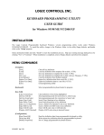
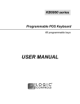
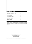
LK1800 series Programmable QWERTY Keyboard 120 key programmable alphanumeric keyboard USER MANUAL NOTICE The manufacturer of the POS programmable keyboard makes no representations or warranties, either expressed or implied, by or with respect to anything in this manual, and shall not be liable for any implied warranties of fitness for a particular purpose or for any indirect, special or consequential damages. Information in this document is subject to change without notice and does not represent a commitment on the part of the manufacturer. FCC NOTICE This device complies with Part 15 of FCC Rules. Operations are subject to the following two conditions: (1) this device may not cause harmful interference, and (2) this device must accept any interference received, including interference that may cause undesired operation. LOGIC CONTROLS, INC. 355 Denton Ave New Hyde Park, NY 11040 TEL: (516) 248-0400 FAX: (516) 248-0443 Email: [email protected] http://www.logiccontrols.com 2 LK1800 User Manual Rev. 1 TABLE OF CONTENTS FEATURES…………………………………………………………............. 4 CARTON CONTENTS……………………………………………………... 5 MODELS……………………………………………………………………... 5 HARDWARE CONNECTIONS……………………………………………. 6 FUNCTIONALTEST………………………………………………………… 7 UTILITY DISK CONTENTS………………………………………………... 8 INSTALLINGTHE LCI KEYBOARD PROGRAMMING UTILITY………. 9 MENU COMMANDS……………………………………………………….. 10 PROGRAMMING THE LK1800 KEYBOARD........................................ 10 EDITING KEY DEFINITIONS……………………………......................... 12 MODIFYING PROPERTIES OF THE KEYBOARD…………………….. 15 DELIMITED TEXT TEMPLATE FILE…………………………………...... 17 KEY LABEL COLOR……………………………………………………….. 18 PROGRAMMING EXAMPLES……………………………………………. 18 TOKEN NAMES FOR SPECIAL FUNCTION KEYS……………………. 19 EDITING MSR PARAMETERS…………………………………………… 21 SPECIFICATIONS................................................................................. 22 3 LK1800 User Manual Rev. 1 FEATURES • 132 key, programmable alphanumeric keyboard • Optional integrated credit card reader • All 132 keys are programmable; 44 keys are relegendable with transparent key caps • Multiple layers of key definitions and multiple shift levels • Keylock switch for layer selection • Programmed with a powerful Windows-based programming utility software • Create program layout for multiple keyboards – programming utility saves templates as data files • Program up to 1800 characters or codes • Programmable inter-character and inter-string time delays • Patented wedge port technology to daisy chain barcode scanner and/or other external keyboard devices • Full travel, tactile key switches • Programmable without special programming switches, programming kits, TSR programs or the need for internal batteries • PS2 or USB interface available • Includes cable and Windows programming utility 4 LK1800 User Manual Rev. 1 CARTON CONTENTS LK1800 1. 2. 3. 4. 5. Programmable Keyboard LK1800 series Computer interface cable - RJ11 to male PS/2 mouse and keyboard interface (For LK1800U models: RJ45 to USB Type A interface) Programming Utility software and User’s Manual disk Legend label sheet 2 keylock keys MODELS LK1800 LK1800U LK1800M LK1800MU - LK1800 with PS2 interface LK1800 with USB interface LK1800 with integrated MSR, PS2 interface LK1800 with integrated MSR, USB interface 5 LK1800 User Manual Rev. 1 HARDWARE CONNECTIONS The LK1800 can be connected to a PS/2 computer, or computer terminal. The following diagram shows how the keyboard connects to the computer and standard keyboard or other keyboard peripheral (magnetic stripe reader, scanner, etc.). LK1800/LK1800M back panel To peripheral To Computer LK1800U/LK1800MU back panel To Computer NOTE: Before making any connections it is always advisable to turn off the computer. A. Connecting the LK1800 to a PC keyboard port: 1. Use the computer interface cable. Plug the PS/2 Male connectors for the keyboard and mouse into the computer. Connect the RJ11 connector into the “To Computer” connector on the LK1800. (For LK1800U and LK1800MU models connect the USB Type A connector to the computer and then the RJ45 into the “To Computer” connector on the LK1800U.) 2. You may connect your original standard keyboard to the “To Peripheral” connector on the LK1800. This port can also be used for peripherals that use a PS/2 interface. 6 LK1800 User Manual Rev. 1 FUNCTIONAL TEST For testing purposes, your LK1800 keyboard was pre-programmed with a key definition template called LK1800-L1.tpl. The following simple steps will verify that the keyboard is in good working condition: 1. Follow the Hardware Connections directions on page 6 in this manual to connect the LK1800 to your computer. 2. Turn on the computer. 3. Under Windows, open Notepad or any text editing software. Press keys on the keyboard one by one to verify that programmed key definitions are activated. For keyboards with MSR models, swipe a magnetic stripe card across the MSR. Card data should be read out onto the display. 7 LK1800 User Manual Rev. 1 UTILITY DISK CONTENTS All LK1800 keyboards come with a utility software disk. This disk contains several important files: SETUP.EXE LK1800-L1.TPL LK1800-L2.TPL LK1800 User Manual This utility will install the keyboard programming utility on your computer. Use this utility with the keyboard attached. These templates were pre-programmed into the keyboard and match the legend shown below. If you have any questions on how to program a particular key you can refer back to this template to see how it was originally programmed. This guide explains how to program the LK1800 using the LCI Keyboard utility that was installed through the SETUP.EXE file. LK1800 Programming Utility 8 LK1800 User Manual Rev. 1 INSTALLING THE LCI KEYBOARD PROGRAMMING UTILITY 1. Make sure the LK1800 is attached to the computer. 2. Double click the SETUP.EXE file on the utility diskette. 3. Select the destination folder if necessary and click “Install” to start the installation process. Skip any warning messages by clicking “Yes” or “Continue”. 4. When installation is completed, reboot the computer. 5. Utility can be started through Windows by clicking on Start→Programs→LCI Keyboard Utility 6. Select Keyboard type LK1800 from menu bar to show the LK1800 programming interface. Before programming, read the template from the keyboard or load the LK1800-L1.tpl template file. Select Template→Load→LK1800-L1.tpl (you will have to navigate to this file within the folder that the LKWN.exe file is located). (You may also use the LCI Keyboard Programming Utility by double-clicking the LKWN.EXE program file in the destination folder where the utility is installed.) 9 LK1800 User Manual Rev. 1 MENU COMMANDS [Template] [New] [Load] [Save] [Save As] [Load Default] [Import Text Data] [Export Text Data] [Exit] [Keyboard] [Key Edit] [Clear Current Key] [Set ASCII Mode] [Set ScanCode Mode] [Insert Caps Code] [Insert Delay Time] [Enter Level Separator] [Enter Shift Level code] [Enter ASCII Code] [Switch ASCII Display mode] [Select Scan Code] [Configuration] [Read From KB] [Write Into KB] [Config KB Properties] [Config MR Properties] [Testing] [Keyboard Output] Clear all key definitions. Load key definitions from template file on disk. (*.TPL) Save key definitions to template file on disk. (*.TPL) Save key definitions to template file on disk with new Filename. (*.TPL) Load key definitions from default template. Import key definitions data from a text file. (*.TXT) Export key definitions data to a text file (*.TXT) Exit programming utility Select programmable keyboard model to program (LK8000, LK1600 or LK1800) Clear definition of key being highlighted Set programming mode for current key to ASCII Code Set programming mode for current key to Scan Code Insert [Caps] function in key definition Insert inter-string delay in key definition Insert a Multi-level Separator Code in key definition Insert a Multi-level Shift Code in key definition Enter ASCII code value (1-240) directly Display ASCII code string in decimal format Displays an Input Scan Code Dialog Box with a drop down list for various Scan Codes (F6, Backspace, Space, Tab, etc.) Read key definition data from programmable keyboard to utility Write current key definition data into programmable keyboard Set or Change programmable keyboard features Set or Change optional Magnetic Stripe Reader properties You may test the keys you have programmed by selecting this function which opens a Test dialog box 10 LK1800 User Manual Rev. 1 PROGRAMMING THE KEYBOARD 1. Connecting the Keyboard For PS/2 versions: Connect the LK1800 to the PC with the special interface cable provided. Plug the standard PC keyboard to the female PS/2 connector on the interface cable and the male PS/2 connector to the computer. For USB versions: Connect the LK1800 to any USB port on the computer. 2. Starting the Utility Start the Programming Utility by double clicking on the “KBWN” short-cut icon or by going to Start→Programs→Logic Controls Utilities→LKWN (Folder)→LKWN. You may also double click the LKWN.EXE icon in the folder where the utility is installed. 3. Select the Communication Port Select the appropriate communication port by selecting either “USB” or “PS/2” in the drop down menu. 4. Select your keyboard model Depending on what model keyboard you have select from the Keyboard menu the LK8000, LK1600 or LK1800. 5. Preparing the Template A new template can be prepared by entering new contents for each key position. Alternatively, an old template can be brought into the utility for editing. (LOAD from a .TPL file, IMPORT from a .TXT file, or READ from the Keyboard). Modify properties of the keyboard in the Properties dialog if necessary. For the LK1800M or LK1800MU with the optional integrated magnetic stripe reader both keyboard and MSR programming data will be saved into a single template file. 6. Writing into the Keyboard It is strongly advised that the template should be first saved into a .TPL template file for future reference and for programming multiple keyboards. Then, click Configuration→Write into KB on the Menu bar or click on the “Down Arrow” icon on the toolbar to write the template into the keyboard. 11 LK1800 User Manual Rev. 1 EDITING KEY DEFINITIONS 1. Selecting Keys to Edit Use Shift Key and the Arrows Keys on the standard keyboard to select the key for editing. Hold down the shift key and hit the arrow keys until the key to be edited is being highlighted. 2. Checking Key Definitions The current key definition is shown on the single line “Key Content” text box below the keyboard layout. 3. Selecting Programming Modes Programming mode is selectable for each individual key. Click on Key Edit menu or the icon on the toolbar to select the desired mode. Scan Code Mode Key definition entered as Scan Codes (codes that are sent by a standard keyboard to the PC) Allow entry of special key functions (e.g. F1 to F12, Shift, Ctrl, Alt, Arrows Keys, Windows Keys, Caps Lock, NumLock, Number pad keys, etc.) Emulate exact key operation sequences. Upper/Lower case status depends on Caps Lock and Shift key status. ASCII Code Mode • Key definition entered as ASCII string of characters. • Simplify programming for entry of text string in the key definition (e.g. for entering login names, passwords, item names etc.) Note that if the text string is case sensitive, it is better to enable the “Use <Alt>+number key to make ASCII code” option in the Configuration→Config KB Properties menu. • Send out ASCII codes in RS232 mode (optional interface). Note that keys programmed with Scan Code mode will send out Scan Codes via the RS232 port. If actual ASCII codes are required, all keys have to be programmed in ASCII mode. In this case, special function keys cannot be programmed. • Special key functions that are not part of standard ASCII code (e.g. F1 to F12, Shift, Ctrl, Alt, Arrows Keys, Windows Keys etc.) cannot be programmed in ASCII mode. • Decimal equivalent numeric values for ASCII codes (only 1 to 240 allowed) can be directly entered. • ASCII mode can also be used to enter Scan Codes by entering the key token names. 4. Entering Key Definitions Scan Code Mode • In Scan Code mode, pressing a key will enter that key in the definition and shown as the key name enclosed between square brackets, [ ]. 12 LK1800 User Manual Rev. 1 • • • • For special function keys, use <ESC> and <Function Key> to enter their scan code in this mode. For example, to program <F9> into the key position, hit <ESC> first, followed by <F9>. To program <ESC>, hit <ESC> twice. Since the following 4 keys are used by Windows, we cannot use <ESC> + <Function Key> to program these keys: <F6>, <F10>, <Alt>, <PrintScreen>. These keys have to be programmed in ASCII mode by entering the key token names. The scan codes for multiple keys entered into one key will act as if all the keys were pressed consecutively without releasing the previous one. At the same time these keys will be released when the key at the programmable keyboard is released. Thus, to program <Shift-F2>, just enter <ESC>, <Shift>, <ESC> <F2>. To program <Ctrl-A>, just enter <ESC>, <Ctrl>, <a>. If a certain key has to act as if it is released within the programming string before the actual key is released, “release codes” have to be inserted manually: o For regular keys (including Shift, RightShift, and Ctrl), insert <ESC> & <f> followed by the key to be “released”. For example, to simulate press and release of the <b> key, enter <b>, <ESC>, <f>, <b>. When <ESC> & <f> is entered, the display will show [0F0]. To release <Ctrl> key, enter <ESC>, <f>, <ESC>, <Ctrl>. o There are some keys that need special code combinations. For example, to release the <RightCtrl> key,use <ESC>,<e>,<ESC>,<f>,<ESC>,<Ctrl>. It will be shown as “[0E0][0F0][Ctrl]”. o For releasing <Alt> and <RightAlt>, type in [0F0][Alt] or [0E0][0F0][RightAlt] directly in ASCII mode. ASCII Code Mode • In ASCII mode, pressing a regular key will enter that key in the definition and be shown as a string of characters. Special function keys will be ignored or used to control entry of data (e.g. Backspace will erase previous character). • There are some special codes used in ASCII code mode: o [Caps] Emulates function of CapsLock key. Used in RS232 mode to emulate Caps Lock function for QWERTY keyboards. To insert [Caps] o o o o function, click on the icon on the toolbar. [CR] Carriage Return code. Used in RS232 mode to emulate <Enter> function. [[ Enters the character ‘[‘ character. ]] Enters the character ‘]’ character. [Separator] Separator Code used in Multi-level definition. Used to separate several definitions codes that work in combination with Multishift-level function key. Click on Code. 13 LK1800 User Manual Rev. 1 icon to insert a Level Separator o • [ShiftLevel*] Multi-shift-level function key definition for different shift levels (* is from 1 to 9). To define a Multi-shift-level function key, click icon and enter the level number. on the Decimal equivalent numeric values for ASCII codes (only 1 to 240 icon on the tool allowed) can be entered directly by clicking on the bar or Key Edit→Enter ASCII Code on the menu bar. After code entry, the ASCII code will be shown as a normal character or as blocks if the code is a non-displayable character. To view the decimal value, click on • the icon on the tool bar or Key Edit→Switch ASCII Display mode on the menu bar. The decimal value will be shown as [xxx]. Special Function keys and scan codes can also be entered in ASCII code mode by entering the token names of the keys as a character string. For example, to define a key to press and release <a>, enter the string “[A][0F0][A]”. However, ASCII code and Scan code should NOT be mixed together in one key. o Each key is entered as a character string enclosed between square brackets, [ ]. For example, [Ctrl], [Alt], [Enter], [A], [B], [1], [2], [=], [PAD3], [ESC] etc. o Full List of all token names of the keys can be found at end of this menu or click on Help→Key Word List o Token names are case sensitive. 5. Special Features A. Multi-Shift-Level Function • A single key can be programmed to output different codes when combined with the Multi-Shift-Level function keys. • To program multiple definitions into a single key, enter the different definitions separated by the [Separator]. The [Separator] can be inserted by clicking on • • • the icon on the tool bar or Key Edit→Enter Level Separator on the menu bar. It will be shown in the definition content as [Separator]. The definition content before the first [Separator] corresponds to the normal key output. The first definition content after the first [Separator] will be the Shift Level 1 output. Definition after second [Separator] will be the Shift Level 2 output, and so on up to ShiftLevel 9. Certain designated keys will be programmed as Multi-Shift -Level function keys for activating multiple definition output of the multi-definition key. MultiShift-Level function keys can only be programmed under ASCII Code mode. To program a key as Multi-Shift-Level function key, click on the icon on the tool bar or Key Edit→Enter Shift Level code. The definition will be shown as [ShiftLevel1] to [ShiftLevel9] corresponding to the Shift Level selected. After the keyboard is programmed, holding down [ShiftLevel1] key and then press the multi-definition key will send out Level 1 definition. Holding down 14 LK1800 User Manual Rev. 1 [ShiftLevel2] key and then press the multi-definition key will send out Level 2 definition, and so on. B. Inter-string Delay • A delay time up to 100 seconds can be inserted between key stroke outputs by clicking on the icon on the tool bar or Key Edit→Insert Delay Time on the menu bar. For example inserting [Delay2] will cause keyboard to pause 2 seconds before sending out subsequent output. (Note: After editing the template, it has to be written into the keyboard before the new key definitions can be used with the keyboard. In addition to writing to the keyboard, it is recommended that the template is saved into a .TPL template file for future reference and for programming multiple keyboards.) 15 LK1800 User Manual Rev. 1 MODIFYING PROPERTIES OF THE KEYBOARD After key definitions are finished, click on the item Configuration→Config KB Properties on the menu bar or click on the “Modify Properties” icon on the toolbar to set or change programmable keyboard features. Config OPOS/JPOS • You may configure the keyboard according to which standard, OPOS/JPOS, your POS application is running. Send break-code for scan-code mode key • Enables the transmission of break codes for each scan codes programmed into the keyboard. A break code is a code that is sent to tell the PC that the key is being released. Enable beep when a key typed • Enables the entire keyboard from beeping when any key is depressed. No beeping if a key is not defined • If a key has no definition, it will not beep when depressed. Translate code set #2 for PC/AT • Enables the output of the keyboard to be translated into AT scan code. Use <ALT> +number key to make ASCII code • Enables the use of ALT key along with the numeric keypad to generate codes for definitions programmed in ASCII mode. This will allow output of ASCII characters in the specified upper or lower case independent of the Caps Lock status and Shift key status. Enable typematic for scan code • Enables keys programmed with scan code mode to repeat key outputs as long as the key remains depressed. Enable typematic for ASCII code • Enables keys programmed with ASCII code mode to repeat character output as long as the key remains depressed. Inter-character delay (ms) • The time delay between characters can be adjusted from 1 millisecond to 250 milliseconds. This delay is set for all key strokes or characters programmed into the keyboard. This feature should not be confused with the Interstring Delay feature. 16 LK1800 User Manual Rev. 1 DELIMITED TEXT TEMPLATE FILE The new programmable keyboard utility can import and export a delimited text file directly. The text file may have two columns and as many rows as number of keys (See the example .TXT file in the utility diskette). Columns are delimited by commas and rows are delimited by <Enter>. The first column is key’s name that will appear on the utility’s key layout screen. These names can be also changed. The second column is key’s definition. • • • All rules and limitations on key definitions apply. Do not mix Scan Code and ASCII definitions. As the characters ‘[‘, ‘]’, ‘\’ and ‘,’ have special meanings or functions, when they are used in the text file in the key name label field or key definition content field, following format has to be used: [ [[ ] ]] \ \\ , \, Importing a Delimited Text File • • • • Use any text editor (e.g. Notepad) to create/edit a text file or use the Export Text Data function to convert the currently loaded template into a text file. Start the utility and click on Template→Import Text Data. Enter the text file name and hit <Enter>. If the file is not imported correctly, check if the text file has 2 columns and the number of row is equal to the number of key in programmable keyboard. Also check the proper format of ‘[‘, ‘]’, ‘\ ’ and ‘,’. Exporting a Delimited Text File • • • • • The simplest way to create a properly formatted template text file is to use the Export function. Start the utility and edit a new template, load from .TPL template file or read from keyboard. Click on Template→Export Text Data. Enter the text file name and hit <Enter>. The exported text file will have key name labels currently used on the screen. The name label field in the text file can then be edited with any text editor. When the new text file is imported the next time, the edited key names will be used as a label on the screen. (Note that loading a .TPL template file will not change the key labels). 17 LK1800 User Manual Rev. 1 KEY LABEL COLOR To identify the status of a key during template editing, the key label is displayed in three different colors. • Black - The key is blank with no definition. • Blue - When a template is loaded from file or read from keyboard, all keys that are not blank will be displayed in blue. • Green - When a key is modified after a template load or keyboard read, it will be changed to green to identify that this key has been changed from the original template. In this example of the LK1800 template, the F33 key is a blank key and is indicated by the color black. 18 LK1800 User Manual Rev. 1 In this example of the LK1800 template, the F33 key is a defined key and is indicated by the color blue. In this example of the LK1800 template, the F33 key is a modified key and is indicated by the color green. 19 LK1800 User Manual Rev. 1 PROGRAMMING EXAMPLES 1. Special Features To program key sequence <Ctrl-A> then <F9>, the <Ctrl> key need to be released before pressing <F9>. Otherwise, the definition will be interpreted as <Ctrl-A>, <CtrlF9>. • [Ctrl][A][0F0][Ctrl][F9] 2. Multi-Shift-Level Function This function programs a key that contains several levels of definitions such as “Small Coke”, “Medium Coke”, “Large Coke”. When pressing this key, the actual output will be any of the 3 strings. We may call this a multi-definition key. • Small Coke[Separator]Medium Coke[Separator]Large Coke. Two other keys are programmed as the Multi-Shift-Level function keys, Level 1 and Level 2. • [ShiftLevel1] • [ShfitLevel2] If the multi-definition key is pressed alone, message “Small Coke” will be sent out. If the [ShiftLevel1] key is held down and the multi-definition key is pressed, message “Medium Coke” will be sent out. If the [ShiftLevel2] key is held down and the multidefinition key is pressed, message “Large Coke” will be sent out. 3. Inter-string Delay Sometimes, when a key is pressed, the application software takes time to respond before the next key can be pressed. For example, after pressing <F2>, wait 1 second before entering <3> and <Enter>. • [F2][Delay1][3][Enter] 4. Starting a Windows Program by pressing a Key on the Programmable Keyboard To start a Windows Program, the [Win] key is used activate the Start menu and the Run command is used. Note that the whole key definition has to be done with Scan Code mode. Break codes have to be inserted where necessary to allow Windows to recognize the command string correctly. For example, release Win key, Shift keys and to enter more than one stroke of the same key (e.g. 00). To run a program in path “C:\Program Files\Test\Demo001.exe”, the following key definition is required: • [Win][0E0][0F0][Win][R][C][Shift][;][0F0][Shift][\][P][R][O][G][R][A][M][Space][F][I][L][E][S][\][ T][E][S][T][\][D][E][M][O][0][0F0][0][0][1][.][E][X][E][Enter] 20 LK1800 User Manual Rev. 1 TOKEN NAMES FOR SPECIAL FUNCTION KEYS There are no ASCII codes for some function keys. They have to be programmed with Scan Codes. In key definitions, the following symbols represent their scan codes. The token name symbols are case sensitive. They have to be entered exactly as shown below. Symbol: [F1] [F2] [F3] [F4] [F5] [F6] [F7] [F8] [F9] [F10] [F11] [F12] [ESC] [Backspace] [Tab] [CapsLock] [Enter] [Shift] [RightShift] [Ctrl] [RightCtrl]* [Alt] [RightAlt]* [Space] [Insert]* [Delete]* [Home]* [End]* [PageUp]* [PageDown]* [ArrowUp]* [ArrowLeft]* [ArrowRight]* [ArrowDown]* [NumLock] [ScrollLk] [PrintScreen] [PauseBreak] [Win]* [RightWin]* [Menu]* [Ctrl+PauseBreak] [Ctrl+PrintScreen] Function Key’s Name Function key <F1> Function key <F2> Function key <F3> Function key <F4> Function key <F5> Function key <F6> Function key <F7> Function key <F8> Function key <F9> Function key <F10> Function key <F11> Function key <F12> Function key <Esc> key <Backspace> key <Tab> key <Caps Lock> key <Enter> key <Shift> on left key <Shift> on right key <Ctrl> on left key <Ctrl> on right key <Alt> on left key <Alt> on right key <space bar> Function key <Insert> Function key <Delete> Function key <Home> Function key <End> Function key <Page Up> Function key <Page Down> Function key <Up Arrow> Function key <Left Arrow> Function key <Right Arrow> Function key <Down Arrow> Function key <Num Lock> Function key <Scroll Lock> Function key <Print Screen> Function key <Pause Break> Function key <Win> on left Function key <Win> on right Function key <Menu> Function key <Ctrl>+<Pause Break> Function key <Ctrl>+<Print Screen> 21 LK1800 User Manual Rev. 1 [Alt+PrintScreen] [PAD0] [PAD1] [PAD2] [PAD3] [PAD4] [PAD5] [PAD6] [PAD7] [PAD8] [PAD9] [PAD+] [PAD-] [PAD*] [PAD/] [PAD.] [PADEnter] [0E0] Function key <Alt>+<Print Screen> number key <0> on keypad number key <1> on keypad number key <2> on keypad number key <3> on keypad number key <4> on keypad number key <5> on keypad number key <6> on keypad number key <7> on keypad number key <8> on keypad number key <9> on keypad number key <+> on keypad number key <-> on keypad number key <*> on keypad number key </> on keypad number key <.> on keypad number key <Enter> on keypad scan code used for generating break codes of special keys (keys listed above with ‘*’) scan code used for generating break codes [0F0] Note: Normal alpha-numeric characters and symbols are represented in scan code as the character itself enclosed in square brackets. For example [A] [B] [C] [1] [2] [3] [-] [;] [,] [/]. 22 LK1800 User Manual Rev. 1 EDITING MSR PARAMETERS (for keyboards equipped with optional MSR) Before editing the parameters, please refer to the user manual of the Point-of-Sale software or credit card verification software to find out what are the requirements on the output format. To configure the MSR from the KBWN.exe utility, click the Configure MR icon. 23 LK1800 User Manual Rev. 1 1. Edit the keyboard programming template; or load a template from a file; or read the template from the keyboard. In the programming utility main menu, click Configuration on the menu bar and then click on [Edit MR Data]. You can also click the “MR data edit” icon on the tool bar. The MSR parameter edit dialog box will be displayed. 2. For Prefix, Suffix, and Terminator, following special characters can be inserted with special formatted string (although there are 4 letters in the string, it will be considered as one character): Carriage Return (Enter key) - [CR] Tab (Tab Key) - [TB] IF "[" character is required in the string, enter "[[". For example, "[[T1]" will send out string "[T1]". 3. Card Data Prefix: maximum 4 characters, sent before card data output. Card Data Suffix: maximum 4 characters, sent after card data output. 4. Skip output of track with error: do not output any track that was read with an error, other tracks without error will be sent to computer. No data output with any error: do not output any data if any track was read with an error. 5. Enable beep at good read: when enabled, keyboard sounds a beep after a good card read. Enable 3 beeps at card read error: when enabled, keyboard sounds 3 short beeps after a card read error. 6. Enable Data: enable track data output for each individual track. 24 LK1800 User Manual Rev. 1 Enable LRC: enable LRC output for each track. If enabled, LRC will be sent as 2 hex characters. Hex values A to F (10 to 15) are represented by characters : ; < - > and ? respectively. 7. Enable Start Sentinel: enable individual track "start sentinel" output. Enable Separator: enable individual track "field separator" output. Enable End Sentinel: enable individual track "end sentinel" output. 8. Track Prefix: maximum 8 characters, sent before start sentinel of each track. Track Field Terminator: 1 character, sent before field separators in each track. Track Suffix: maximum 8 characters, sent after end sentinel of each track. 9. Click [OK] after finishing parameter edit. Write the template into the keyboard. Save the template into a file for future reference and for programming multiple keyboards. 10. Verify MSR and keyboard output under Windows Notepad or the POS software. 25 LK1800 User Manual Rev. 1 SPECIFICATIONS 26 LK1800 User Manual Rev. 1