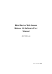
1
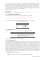
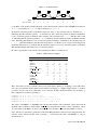
Joint Collaborative Team on Video Coding (JCT-VC)
of ITU-T SG16 WP3 and ISO/IEC JTC1/SC29/WG11
Title:
Status:
Purpose:
Author(s):
Source:
Document: JCTVC-Software Manual
HM Software Manual
Software AHG working document
Information
Frank Bossen
David Flynn
Karsten Sühring
AHG chairs
[email protected]
[email protected]
[email protected]
Abstract
This document is a user manual describing usage of reference software for the HEVC project. It applies
to version 8.1 of the software.
Contents
1
General Information
1
2
Installation and compilation
2
3
Using the encoder
2
3.1 GOP structure table . . . . . . . . . . . . . . . . . . . . . . . . . . . . . . . . . . . . . 2
3.2 Encoder parameters . . . . . . . . . . . . . . . . . . . . . . . . . . . . . . . . . . . . . 6
3.3 Hardcoded encoder parameters . . . . . . . . . . . . . . . . . . . . . . . . . . . . . . . 12
4
Using the decoder
14
List of Tables
1
2
3
4
5
6
7
8
9
10
11
12
13
14
15
16
1
Available project files . . . . .
GOP structure example . . . .
File, I/O and source parameters
Unit definition parameters . .
Coding structure parameters .
Motion estimation parameters
Mode decision parameters . .
Quantization parameters . . .
Entropy coding parameters . .
Slice coding parameters . . . .
Deblocking filter parameters .
Coding tools parameters . . .
VUI parameters . . . . . . . .
Miscellaneous parameters . . .
CommonDef.h constants . . .
Decoder options . . . . . . . .
.
.
.
.
.
.
.
.
.
.
.
.
.
.
.
.
.
.
.
.
.
.
.
.
.
.
.
.
.
.
.
.
.
.
.
.
.
.
.
.
.
.
.
.
.
.
.
.
.
.
.
.
.
.
.
.
.
.
.
.
.
.
.
.
.
.
.
.
.
.
.
.
.
.
.
.
.
.
.
.
.
.
.
.
.
.
.
.
.
.
.
.
.
.
.
.
.
.
.
.
.
.
.
.
.
.
.
.
.
.
.
.
.
.
.
.
.
.
.
.
.
.
.
.
.
.
.
.
.
.
.
.
.
.
.
.
.
.
.
.
.
.
.
.
.
.
.
.
.
.
.
.
.
.
.
.
.
.
.
.
.
.
.
.
.
.
.
.
.
.
.
.
.
.
.
.
.
.
.
.
.
.
.
.
.
.
.
.
.
.
.
.
.
.
.
.
.
.
.
.
.
.
.
.
.
.
.
.
.
.
.
.
.
.
.
.
.
.
.
.
.
.
.
.
.
.
.
.
.
.
.
.
.
.
.
.
.
.
.
.
.
.
.
.
.
.
.
.
.
.
.
.
.
.
.
.
.
.
.
.
.
.
.
.
.
.
.
.
.
.
.
.
.
.
.
.
.
.
.
.
.
.
.
.
.
.
.
.
.
.
.
.
.
.
.
.
.
.
.
.
.
.
.
.
.
.
.
.
.
.
.
.
.
.
.
.
.
.
.
.
.
.
.
.
.
.
.
.
.
.
.
.
.
.
.
.
.
.
.
.
.
.
.
.
.
.
.
.
.
.
.
.
.
.
.
.
.
.
.
.
.
.
.
.
.
.
.
.
.
.
.
.
.
.
.
.
.
.
.
.
.
.
.
.
.
.
.
.
.
.
.
.
.
.
.
.
.
.
.
.
.
.
.
.
.
.
.
.
.
.
.
.
.
.
.
.
.
.
.
.
.
.
.
.
.
.
.
.
.
.
.
.
.
.
.
.
.
.
.
.
.
.
.
.
.
.
.
.
.
.
.
.
.
.
.
.
.
.
.
.
.
.
.
.
.
.
.
.
.
.
.
.
.
.
.
.
.
.
.
.
.
.
.
.
.
.
.
.
.
.
.
.
.
.
.
.
2
4
6
6
7
7
8
8
9
9
10
10
11
12
13
14
General Information
Reference software is being made available to provide a reference implementation of the draft HEVC
standard being developed by the Joint Collaborative Team on Video Coding (JCT-VC) regrouping experts
from ITU-T SG 16 and ISO/IEC SC29 WG11. One of the main goals of the reference software is to
provide a basis upon which to conduct experiments in order to determine which coding tools provide
1
Date saved: 2012-09-29
desired coding performance. It is not meant to be a particularly efficient implementation of anything,
and one may notice its apparent unsuitability for a particular use. It should not be construed to be a
reflection of how complex a production-quality implementation of a future HEVC standard would be.
This document aims to provide guidance on the usage of the reference software. It is widely suspected
to be incomplete and suggestions for improvements are welcome. Such suggestions and general inquiries may be sent to the general JCT-VC email reflector on [email protected]
(registration required).
Bug reporting
Bugs should be reported on the issue tracker set up at http://hevc.kw.bbc.co.uk/trac/
2
Installation and compilation
The software may be retrieved from one of the following SVN servers (mirrored):
• https://hevc.hhi.fraunhofer.de/svn/svn_HEVCSoftware/
• svn://hevc.kw.bbc.co.uk/svn/jctvc-hm/
Table 1 enumerates various project files that are provided for development environments.
Table 1: Available project files
Environment
MS Visual Studio 8
MS Visual Studio 9
Xcode
Linux
3
Location of project file
build/HM vc8.sln
build/HM vc9.sln
HM.xcodeproj
build/linux/makefile
Using the encoder
TAppEncoder
[-h] [-c config.cfg] [--parameter=value]
Option
-h
-c
--parameter=value
Description
Prints parameter usage.
Defines configuration file to use. Multiple configuration files
may be used with repeated –c options.
Assigns value to a given parameter as further described below.
Some parameters are also supported by shorthand “–opt value”.
Sample configuration files are provided in the cfg/ folder.
3.1
GOP structure table
Defines the cyclic GOP structure that will be used repeatedly throughout the sequence. The table should
contain GOPSize lines, named Frame1, Frame2, etc. The frames are listed in decoding order, so Frame1
is the first frame in decoding order, Frame2 is the second and so on. Among other things, the table
specifies all reference pictures kept by the decoder for each frame. This includes pictures that are used
for reference for the current picture as well as pictures that will be used for reference in the future. The
encoder will not automatically calculate what pictures that has to be kept for future references, they
have to be specified. Note that some specified reference frames for pictures encoded in the very first
GOP after an IDR frame might not be available. This is handled automatically by the encoder, so the
reference pictures can be given in the GOP structure table as if there were infinitely many identical GOPs
before the current one. Each line in the table contains the parameters used for the corresponding frame,
separated by whitespace:
Type: Slice type, can be either I, P or B.
POC: Display order of the frame within a GOP, ranging from 1 to GOPSize.
2
Date saved: 2012-09-29
QPOffset: QP offset is added to the QP parameter to set the final QP value to use for this frame.
QPFactor: Weight used during rate distortion optimization. Higher values mean lower quality
and less bits. Typical range is between 0.3 and 1.
temporal id: Temporal layer of the frame. A frame cannot predict from a frame with a higher
temporal id. If a frame with higher temporal IDs is listed among a frame’s reference pictures, it is
not used, but is kept for possible use in future frames.
num ref pics active: Size of reference picture lists L0 and L1, indicating how many reference
pictures in each direction that are used during coding.
ref pic: A value of 1 indicates that this is a reference picture, 0 that it is a non-reference picture.
num ref pics: The number of reference pictures kept for this frame. This includes pictures that
are used for reference for the current picture as well as pictures that will be used for reference in
the future.
reference pictures: A space-separated list of num ref pics integers, specifying the POC of the
reference pictures kept, relative the POC of the current frame. The picture list shall be ordered,
first with negative numbers from largest to smallest, followed by positive numbers from smallest
to largest (e.g. -1 -3 -5 1 3). Note that any pictures not supplied in this list will be discarded
and therefore not available as reference pictures later.
predict: Defines the value of the syntax element inter ref pic set prediction flag. A value of 0
indicates that the reference picture set is encoded without inter RPS prediction and the subsequent
parameters deltaRIdx−1, deltaRPS, num ref idcs and Reference idcs are ignored and do not need
to be present. A value of 1 indicates that the reference picture set is encoded with inter prediction
RPS using the subsequent parameters deltaRIdx−1, deltaRPS, num ref idcs and Reference idcs
in the line. A value of 2 indicates that the reference picture set is encoded with inter RPS but only
the deltaRIdx−1 parameters is needed. The deltaRPS, num ref idcs and Reference idcs values
are automatically derived by the encoder based on the POC and refPic values of the current line
and the RPS pointed to by the deltaRIdx−1 parameters.
deltaRIdx−1: The difference between the index of the curent RPS and the predictor RPS minus
1.
deltaRPS: The difference between the POC of the predictor RPS and POC the current RPS.
num ref idcs: The number of ref idcs to encode for the current RPS. The value is equal to the
value of num ref pics of the predictor RPS plus 1.
reference idcs: A space-separated list of num ref idcs integers, specifying the ref idcs of the inter
RPS prediction. The value of ref idcs may be 0, 1 or 2 indicating that the reference picture is
a reference picture used by the current picture, a reference picture used for future picture or not
a reference picture anymore, respectively. The first num ref pics of ref idcs correspond to the
Reference pictures in the predictor RPS. The last ref idcs corresponds to the predictor picture.
For example, consider the coding structure of Figure 1. This coding structure is of size 4. The pictures
are listed in decoding order. Frame1 shall therefore describe picture with POC = 4. It references picture
0, and therefore has −4 as a reference picture. Similarly, Frame2 has a POC of 2, and since it references
pictures 0 and 4, its reference pictures are listed as -2 2. Frame3 is a special case: even though it
only references pictures with POC 0 and 2, it also needs to include the picture with POC 4, which must
be kept in order to be used as a reference picture in the future. The reference picture list for Frame3
therefore becomes -1 1 3. Frame4 has a POC of 3 and its list of reference pictures is -1 1.
Inter RPS prediction may be used for Frame2, Frame3 and Frame4, hence the predict parameter is set
to 1 for these frames. Frame2 uses Frame1 as the predictor hence the deltaRIdx−1 is 0. Similarly for
Frame3 and Frame4 which use Frame2 and Frame3 as predictors, respectively. The deltaRPS is equal
3
Date saved: 2012-09-29
Figure 1: A GOP structure
B
B
B
B
B
B
I
P
P
POC
0
1
2
3
4
5
6
7
8
Decode Order
0
3
2
4
1
7
6
8
5
to the POC of the predictor minus the POC of the current picture, therefore the deltaRPS for Frame2 is
4 − 2 = 2, for Frame3 is 2 − 1 = 1 and for Frame4 is 1 − 3 = −2.
In Frame2, reference pictures with POC 0 and 2 are used, so the reference idcs for Frame2 are 1 1
indicating that the reference picture, −4, in Frame1 is still a reference picture in Frame2 and Frame1
is also a reference picture in Frame2. The reference idcs for Frame3 are 1 1 1. The first and second
1s indicating that the reference pictures “−2 2” in Frame2 are still reference pictures in Frame3 and the
last 1 indicating that Frame2 is also a reference picture in Frame3. In Frame 4, the reference idcs are
0 1 1 0. The first 0 indicates that the reference pictures -1 in Frame 3 is no longer a reference picture
in Frame4. The next two 1s indicate that the reference pictures 1 3 are now reference pictures of Frame4.
The final 0 indicates that Frame3 is not a reference picture.
In order to specify this to the encoder, the parameters in Table 2 could be used.
Table 2: GOP structure example
Type
POC
QPoffset
QPfactor
temporal id
num ref pics active
ref pic
num ref pics
reference pictures
predict
deltaRIdx−1
deltaRPS
num ref idcs
reference idcs
Frame1
Frame2
Frame3
Frame4
P
4
1
0.5
0
1
1
1
−4
0
B
2
2
0.5
1
1
1
2
−2 2
1
0
2
2
11
B
1
3
0.5
2
1
0
3
−1 1 3
1
0
1
3
111
B
3
3
0.5
2
1
0
2
−1 1
1
0
−2
4
0110
Here, the frames used for prediction have been given higher quality by assigning a lower QP offset.
Also, the non-reference frames have been marked as belonging to a higher temporal layer, to make it
possible to decode only every other frame. Note: each line should contain information for one frame, so
this configuration would be specified as:
Frame1:
Frame2:
Frame3:
Frame4:
P
B
B
B
4
2
1
3
1
2
3
3
0.5
0.5
0.5
0.5
0
1
2
2
1
1
1
1
1
1
0
0
1
2
3
2
-4
-2
-1
-1
0
2 1 0 2 2 1 1
1 3 1 0 1 3 1 1 1
1 1 0 -2 4 0 1 1 0
The values of deltaRIdx−1, deltaRPS, num ref idcs and reference idcs of FrameK can be derived from
the POC value of FrameK and the POC, num ref pics and reference pictures values of FrameM , where
K is the index of the RPS to be inter coded and the M is the index of the reference RPS, as follows.
Note: The above (automatic) generation of the inter RPS parameter values has been integrated into the
encoder, and is activated by the value of predict = 2 followed by the value of deltaRIdx−1, only, as
described above.
4
Date saved: 2012-09-29
deltaRIdxK − 1 ← K − M − 1 ;
deltaRPSK ← POCM − POCK ;
num ref idcsK ← num ref picsM + 1 ;
for j ← 0 to num ref picsM do
for i ← 0 to num ref idcsK do
if reference picturesM,j + deltaRPSK == reference picturesK,i then
if reference picturesK,i is used by the current frame then reference idcsK,j = 1
;
else reference idcsK,j = 2 ;
else
reference idcsK [j] = 0 ;
end
end
end
/* reference picturesM,num ref pics does not exist and is assumed to
M
be 0
*/
5
Date saved: 2012-09-29
3.2
Encoder parameters
Table 3: File, I/O and source parameters
Option
Shorthand
Default
Description
InputFile
-i
Specifies the input video file.
Video data must be in a raw 4:2:0 planar format (Y0 CbCr).
Note: When the bit depth of samples is larger than 8, each sample is encoded in 2 bytes (little endian, LSB-justified).
BitstreamFile
-b
Specifies the output coded bit stream file.
ReconFile
-o
Specifies the output locally reconstructed video file.
SourceWidth
SourceHeight
-wdt
-hgt
InputBitDepth
InternalBitDepth
0
0
Specifies the width and height of the input video in luma samples.
8
Specifies the bit depth of the input video.
0
(InputBitDepth)
Specifies the bit depth used for coding.
If the input video is a different bit depth to InternalBitDepth, it is automatically converted by:
Pel ∗ 2InternalBitDepth
2InputBitDepth
Note: The effect of this option is as if the input video is externally converted
to the InternalBitDepth and then coded with this value as InputBitDepth.
The codec has no notion of two different bit depths.
OutputBitDepth
0
(InternalBitDepth)
CroppingMode
0
Specifies the cropping/padding parameters to be applied to the input video.
The following modes are available:
0 No cropping / padding
1 Automatic padding to the next minimum CU size
2 Padding according to parameters HorizontalPadding and VerticalPadding
3 Cropping according to parameters CropLeft, CropRight, CropTop
and CropBottom
0
Specifies the horizontal and vertical padding to be applied to the input video
in luma samples. Must be a multiple of the chroma resolution (e.g. a multiple of two for 4:2:0).
0
Specifies the horizontal and vertical cropping to be applied to the input
video in luma samples. Must be a multiple of the chroma resolution (e.g. a
multiple of two for 4:2:0).
HorizontalPadding
VerticalPadding
-pdx
-pdy
CropLeft
CropRight
CropTop
CropBottom
Specifies the bit depth of the output locally reconstructed video file.
Note: This option has no effect on the decoding process.
FrameRate
-fr
0
Specifies the frame rate of the input video.
Note: This option only affects the reported bit rates.
FrameSkip
-fs
0
Specifies a number of frames to skip at beginning of input video file.
FramesToBeEncoded
-f
0
(all)
Specifies the number of frames to be encoded.
Table 4: Unit definition parameters
Option
MaxCUWidth
Shorthand
Default
Description
64
Defines the maximum CU width.
Continued...
6
Date saved: 2012-09-29
Table 4: Unit definition parameters (Continued)
Option
Shorthand
Default
Description
MaxCUHeight
64
Defines the maximum CU height.
MaxCUSize
64
Defines the maximum CU size.
4
Defines the depth of the CU tree.
MaxPartitionDepth
-h
QuadtreeTULog2MaxSize
6
(= log2 (64))
Defines the Maximum TU size in logarithm base 2.
QuadtreeTULog2MinSize
2
(= log2 (4))
Defines the Minimum TU size in logarithm base 2.
QuadtreeTUMaxDepthIntra
1
Defines the depth of the TU tree for intra CUs.
QuadtreeTUMaxDepthInter
2
Defines the depth of the TU tree for inter CUs.
Table 5: Coding structure parameters
Option
Shorthand
Default
Description
IntraPeriod
-ip
−1
Specifies the intra frame period. A value of −1 implies an infinite period.
DecodingRefreshType
-dr
0
Specifies the type of decoding refresh to apply at the intra frame period
picture.
0 Applies an I picture (not a clean random access point).
1 Applies a non-IDR clean random access point (open GOP).
2 Applies an IDR random access point (closed GOP).
GOPSize
-g
1
Specifies the size of the cyclic GOP structure.
FrameN
ListCombination
Multiple options that define the cyclic GOP structure that will be used repeatedly throughout the sequence. The table should contain GOPSize elements.
See section 3.1 for further details.
-lc
true
Enables or disables the use of the combined reference list for uni-prediction
in B-slices.
0 Reference list 0 and reference list 1 are identical and reference list 0
is used as the combined reference list.
1 The combined reference list is derived from reference list 0 and reference list 1.
NB: LComb can only be 0 in low delay coding (more precisely, when list 0
and list 1 are the same)
Table 6: Motion estimation parameters
Option
Shorthand
FastSearch
SearchRange
BipredSearchRange
-sr
Default
Description
true
Enables or disables the use of a fast motion search.
0 Full search method
1 Fast search method
96
Specifies the search range used for motion estimation.
Note: the search range is defined around a predictor. Motion vectors derived
by the motion estimation may thus have values larger than the search range.
4
Specifies the search range used for bi-prediction refinement in motion estimation.
Continued...
7
Date saved: 2012-09-29
Table 6: Motion estimation parameters (Continued)
Option
Shorthand
Default
Description
HadamardME
true
Enables or disables the use of the Hadamard transform in fractional-pel
motion estimation.
0 SAD for cost estimation
1 Hadamard for cost estimation
ASR
false
Enables or disables the use of adaptive search ranges, where the motion
search range is dynamically adjusted according to the POC difference between the current and the reference pictures.
SearchRange = Round SearchRange ∗ ADAPT SR SCALE ∗
abs(POCcur−POCref)
RateGOPSize
Table 7: Mode decision parameters
Option
LambdaModifierN
Shorthand
-LMN
FEN
Default
Description
1.0
Specifies a value that is multiplied with the Lagrange multiplier λ, for use
in the rate-distortion optimised cost calculation when encoding temporal
layer N .
N may be in the range 0–7.
false
Enables or disables the use of fast encoder mode. When enabled, the following occurs:
• In the SAD computation for blocks having size larger than 8, only
the lines of even rows in the block are considered.
• The number of iterations used in the bi-directional motion vector
refinement in the motion estimation process is reduced from 4 to 1.
FDM
true
Enables or disables the use of fast encoder decisions for 2Nx2N merge
mode. When enabled, the RD cost for the merge mode of the current candidate is not evaluated if the merge skip mode was the best merge mode for
one of the previous candidates.
Table 8: Quantization parameters
Option
Shorthand
QP
-q
CbQpOffset
CrQpOffset
-cbqpofs
-crqpofs
Default
30.0
MaxCuDQPDepth
RDOQ
DeltaQpRD
Specifies the base value of the quantization parameter.
0
0
Global offset to apply to the luma QP to derive the QP of Cb and Cr respectively. These options correspond to the values of cb qp offset and cr qp offset, that are transmitted in the PPS. Valid values are in the range [−12, 12].
0
Defines maximum depth of a minimum CuDQP for sub-LCU-level delta
QP. MaxCuDQPDepth shall be greater than or equal to SliceGranularity.
true
0
-dqr
Description
Enables or disables rate-distortion-optimized quantization.
Specifies the maximum QP offset at slice level for multi-pass slice encoding. When encoding, each slice is tested multiple times by using slice QP
values in the range [−DeltaQpRD, DeptaQpRD], and the best QP value
is chosen as the slice QP.
Continued...
8
Date saved: 2012-09-29
Table 8: Quantization parameters (Continued)
Option
Shorthand
MaxDeltaQP
-d
dQPFile
-m
AdaptiveQpSelection
-aqps
Default
0
Description
Specifies the maximum QP offset at the largest coding unit level for the
block-level adaptive QP assignment scheme. In the encoder, each largest
coding unit is tested multiple times by using the QP values in the range
[−MaxDeltaQP, MaxDeltaQP], and the best QP value is chosen as the
QP value of the largest coding unit.
Specifies a file containing a list of QP deltas. The n-th line (where n is 0
for the first line) of this file corresponds to the QP value delta for the picture
with POC value n.
RecalculateQPAccordingToLambda
false
Specifies whether QP values for non-I frames will be calculated on the fly
based on statistics of previously coded frames.
false
Recalculate QP values according to lambda values. Do not suggest to be
enabled in all intra case.
Table 9: Entropy coding parameters
Option
Shorthand
SBACRD
Default
Description
true
Enables or disables the use of bit counts from arithmetic coder in ratedistortion decisions.
Table 10: Slice coding parameters
Option
SliceMode
Shorthand
Default
Description
0
Controls the slice partitioning method in conjunction with SliceArgument.
0 Single slice
1 Maximum number of CUs (at a depth of SliceGranuarity) per slice
2 Maximum number of bytes per slice
SliceArgument
EntropySliceMode
Specifies the maximum number of CUs or bytes in a slice depending on the
SliceMode setting.
0
Enables entropy slice coding. When set to 1, the parameter SliceArgument
will specify the maximum number of CUs in a slice. When set to 2, the
parameter SliceArgument will specify the number of bytes (LCEC) or bins
(CABAC) in a slice.
EntropySliceArgument
WaveFrontSynchro
Defines the maximum number of CUs or bytes/bins in an entropy slice depending on the SliceMode setting.
false
Enables the use of specific CABAC probabilities synchronization at the beginning of each line of CTBs in order to produce a bitstream that can be
encoded or decoded using one or more cores.
NumTileColumnsMinus1
NumTileRowsMinus1
0
Specifies the tile based picture partitioning geometry as
NumTileColumnsMinus1 + 1 × NumTileRowsMinus1 + 1 columns
and rows.
UniformSpacingIdc
0
Controls the mode used to determine per row and column tile sizes.
0 Each tile column width and tile row height is explicitly set by
ColumnWidthArray and RowHeightArray respectively
1 Tile columns and tile rows are uniformly spaced.
Continued...
9
Date saved: 2012-09-29
Table 10: Slice coding parameters (Continued)
Option
Shorthand
Default
Description
ColumnWidthArray
RowHeightArray
Specifies a space or comma separated list of widths and heights, respectively, of each tile column or tile row. The first value in the list corresponds
to the leftmost tile column or topmost tile row.
Table 11: Deblocking filter parameters
Option
Shorthand
Default
Description
LoopFilterDisable
false
Enables or disables the in-loop deblocking filter.
LFCrossSliceBoundaryFlag
true
Enables or disables the use of in-loop filtering across slice boundaries.
DeblockingFilterControlPresent
false
Enables or disables the presence of the deblocking filter control parameters
in the picture parameter set and in the slice header. When disabled, the
default deblocking filter parameters are used.
Table 12: Coding tools parameters
Option
Shorthand
Default
Description
SAO
true
Enables or disables the sample adaptive offset (SAO) filter.
SAOLcuBoundary
false
Enables or disables SAO parameter estimation using non-deblocked pixels
for LCU bottom and right boundary areas.
ConstrainedIntraPred
false
Enables or disables constrained intra prediction. Constrained intra prediction only permits samples from intra blocks in the same slice as the current
block to be used for intra prediction.
TransquantBypassEnableFlag
false
Enables or disables the ability to bypass the transform, quantization and
filtering stages at CU level. This option corresponds to the value of transquant bypass enable flag that is transmitted in the PPS.
See CUTransquantBypassFlagValue for further details.
0
Controls the per CU transformation, quantization and filtering mode decision. This option corresponds to the value of the per CU cu transquant bypass flag.
0 Bypass is not performed on any CU
1 Bypass is performed on all CUs
This option has no effect if TransquantBypassEnableFlag is disabled.
CUTransquantBypassFlagValue
PCMEnabledFlag
false
Enables or disables the use of PCM.
PCMLog2MaxSize
5
(= log2 (32))
Specifies log2 of the maximum PCM block size. When PCM is enabled,
the PCM mode is available for 2Nx2N intra PUs smaller than or equal to
the specified maximum PCM block size
PCMLog2MinSize
3
Specifies log2 of the minimum PCM block size. When PCM is enabled,
the PCM mode is available for 2Nx2N intra PUs larger than or equal to the
specified minimum PCM block size.
When larger than PCMLog2MaxSize, PCM mode is not used.
PCMInputBitDepthFlag
1
If enabled specifies that PCM sample bit-depth is set equal to InputBitDepth. Otherwise, it specifies that PCM sample bit-depth is set equal to
InternalBitDepth.
Continued...
10
Date saved: 2012-09-29
Table 12: Coding tools parameters (Continued)
Option
Shorthand
Default
PCMFilterDisableFlag
Description
false
If enabled specifies that loop-filtering on reconstructed samples of PCM
blocks is skipped. Otherwise, it specifies that loop-filtering on reconstructed
samples of PCM blocks is not skipped.
weighted pred flag
-wpP
false
Controls the use of weighted prediction in P slices.
weighted bipred idc
-wpB
0
Controls the use of weighted prediction in B slices.
0 Disabled
1 Explicit weighted prediction
2 Implicit weighted prediction
SignHideFlag
-SBH
true
TMVPMode
If enabled specifies that for each 4x4 coefficient group for which the number of coefficients between the first nonzero coefficient and the last nonzero
coefficient along the scanning line exceeds 4, the sign bit of the first nonzero
coefficient will not be directly transmitted in the bitstream, but may be inferred from the parity of the sum of all nonzero coefficients in the current
coefficient group.
1
Controls the temporal motion vector prediction mode.
0 Disabled for all slices.
1 Enabled for all slices.
2 Disabled only for the first picture of each GOPSize.
TransformSkip
false
Enables or disables transform-skipping mode decision for 4x4 TUs 1 .
TransformSkipFast
false
Enables or disables reduced testing of the transform-skipping mode decision for chroma TUs. When enabled, no RDO search is performed for
chroma TUs, instead they are transform-skipped if the four corresponding
luma TUs are also skipped.
This option has no effect if TransformSkip is disabled.
Table 13: VUI parameters
Option
VuiParametersPresent
Shorthand
-vui
AspectRatioInfoPresent
Default
Description
false
Enable generation of vui parameters().
false
Signals whether aspect ratio idc is present.
AspectRatioIdc
0
aspect ratio idc
SarWidth
0
Specifies the horizontal size of the sample aspect ratio.
SarHeight
0
Specifies the vertical size of the sample aspect ratio.
OverscanInfoPresent
false
Signals whether overscan info present flag is present.
OverscanAppropriate
false
Indicates whether cropped decoded pictures are suitable for display using
overscan.
0 Indicates that the decoded pictures should not be displayed using
overscan.
1 Indicates that the decoded pictures may be displayed using overscan.
VideoSignalTypePresent
false
Signals whether video format, video full range flag, and colour description present flag are present.
VideoFormat
5
Indicates representation of pictures.
Continued...
1
Enables transform skip enabled and per 4x4 TU tests
11
Date saved: 2012-09-29
Table 13: VUI parameters (Continued)
Option
Shorthand
Default
Description
VideoFullRange
false
Indicates the black level and range of luma and chroma signals.
0 Indicates that the luma and chroma signals are to be scaled prior to
display.
1 Indicates that the luma and chroma signals are not to be scaled prior
to display.
ColourDescriptionPresent
false
Signals whether colour primaries, transfer characteristics and matrix coefficients are present.
ColourPrimaries
2
Indicates chromaticity coordinates of the source primaries.
TransferCharateristics
2
Indicates the opto-electronic transfer characteristics of the source.
MatrixCoefficients
2
Describes the matrix coefficients used in deriving luma and chroma from
RGB primaries.
false
Signals whether chroma sample loc type top field and chroma sample loc type bottom field are present.
ChromaLocInfoPresent
ChromaSampleLocTypeTopField
0
Specifies the location of chroma samples for top field.
ChromaSampleLocTypeBottomField
0
Specifies the location of chroma samples for bottom field.
NeutralChromaIndication
false
Indicates that the value of all decoded chroma samples is equal to
1¡¡(BitDepthCr-1).
BitstreamRestriction
false
Signals whether bitstream restriction parameters are present.
TilesFixedStructure
false
Indicates that each active picture parameter set has the same values of the
syntax elements related to tiles.
MotionVectorsOverPicBoundaries
false
Indicates that no samples outside the picture boundaries are used for inter
prediction.
MaxBytesPerPicDenom
2
Indicates a number of bytes not exceeded by the sum of the sizes of the
VCL NAL units associated with any coded picture.
MaxBitsPerMinCuDenom
1
Indicates an upper bound for the number of bits of coding unit() data.
Log2MaxMvLengthHorizontal
15
Indicate the maximum absolute value of a decoded horizontal MV component in quarter-pel luma units.
Log2MaxMvLengthVertical
15
Indicate the maximum absolute value of a decoded vertical MV component
in quarter-pel luma units.
Table 14: Miscellaneous parameters
Option
Shorthand
SEIpictureDigest
3.3
Default
Description
0
Enables or disables the calculation and insertion of the picture digest SEI
messages.
0 Disabled
1 Transmits MD5 in SEI message and writes the value to the encoder
log
Hardcoded encoder parameters
12
Date saved: 2012-09-29
Table 15: CommonDef.h constants
Option
Default
Description
ADAPT SR SCALE
1
Defines a scaling factor used to derive the motion search range is adaptive
(see ASR configuration parameter). Default value is 1.
MAX GOP
64
maximum size of value of hierarchical GOP.
MAX NUM REF
4
maximum number of multiple reference frames
MAX NUM REF LC
8
maximum number of combined reference frames
AMVP MAX NUM CANDS
2
maximum number of final candidates
AMVP MAX NUM CANDS MEM
3
MRG MAX NUM CANDS
5
DYN REF FREE
off
dynamic free of reference memories
MAX TLAYER
8
maximum number of temporal layers
HB LAMBDA FOR LDC
on
use of B-style lambda for non-key pictures in low-delay mode
GPB SIMPLE
on
Fast estimation of generalized B in low-delay mode
GPB SIMPLE UNI
on
Fast estimation of generalized B in low-delay mode for uni-direction
FASTME SMOOTHER MV
on
Fast ME using smoother MV assumption
ADAPT SR SCALE
on
division factor for adaptive search range
CLIP TO 709 RANGE
off
IBDI NOCLIP RANGE
off
restrict maximum value after IBDI to skip clipping
EARLY SKIP THRES
1.5
early skip if RD ¡ EARLY SKIP THRES*avg[BestSkipRD]
MAX NUM REF PICS
16
MAX CHROMA FORMAT IDC
3
TypeDef.h
Numerous constants that guard individual adoptions are defined within source/Lib/TLibCommon/TypeDef.h.
13
Date saved: 2012-09-29
4
Using the decoder
TappDecoder -b str.bin -o dec.yuv [options]
Table 16: Decoder options
Option
SEIPictureDigest
Shorthand
Default
Description
-h
Prints usage information.
-o
Defines reconstructed YUV file name.
-s
0
Defines the number of pictures in decoding order to skip.
-d
0
(Native)
Defines the bit depth of the reconstructed YUV file (a value 0 indicates that
the native bit depth is used)
1
Enable or disable verification of any picture digest SEI messages. When
this parameter is set to 0, the feature is disabled and all messages are ignored. When set to 1 (default), the feature is enabled and the decoder has
the following behaviour:
• For each decoded picture, the MD5 is calculated and written to the
log. If the input bitstream has a picture digest SEI message for the
corresponding decoded picture, the two MD5s are compared. Decoding will continue even if there is a mismatch.
• After decoding is complete, if any MD5sum comparison failed, a
warning is printed and the decoder exits with the status EXIT FAILURE
• The per-picture MD5 log message has the following formats:
[MD5:d41d8cd98f00b204e9800998ecf8427e,(OK)],
[MD5:d41d8cd98f00b204e9800998ecf8427e,(unk)],
[MD5:d41d8cd98f00b204e9800998ecf8427e,(***ERROR***)]
[rxMD5:b9e1...] where, “(unk)” implies that no MD5 was signalled
for this picture, “(OK)” implies that the decoder agrees with
the signalled MD5, “(***ERROR***)” implies that the decoder
disagrees with the signalled MD5. “[rxMD5:...]” is the signalled
MD5 if different.
14
Date saved: 2012-09-29