1
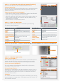
simple innovative
always on security
QUICK START GUIDE
This guide provides step-by-step instructions, with
simple explanations to get you up-and-running.
For further information, please refer to the SafeDial Wireless User Manual.
Installation and Connection Details
1) MOUNTING & ENVIRONMENTAL CONSIDERATIONS
The SDW-100 should be mounted alongside the
alarm panel in a clean and dry location, protected
from water, excessive dust, extreme temperatures
and direct sunlight. The SDI-10 interface module
should be mounted inside the alarm panel enclosure
in order to comply with AS/NZ2201.5:2008.
3) POWER SUPPLY REQUIREMENTS
The SDW-100 and SDI-10 can be powered
from various means:
• Using the power supply provided (recommended)
• Using the alarm panel’s power supply
• A combination of the above
(Please refer to the diagram below.)
ALARM PANEL
Before applying power to the unit, connect the
antenna and all interface wiring.
SAFE-DIAL™ WIRELESS BOX
ZONE x
4
x
ZONE
x
3
ZONE
2
ZONE
1
O
U
T
P
U
T
S
x
x
SDW-100 OUTLAY
x
x
x
POWER
1
12V DC
(–ve)
KEYPAD
ALARM
PANEL
DIALLER
C D + –
BATT
(–ve)
BATT
(+ve)
ALARM
PANEL PLUG
PACK
HEARTBEAT
RJ12
LINK
PSTN
PANEL
+
–
SDW-100
BATTERY
1.3Ah
OFF HOOK
PANEL COMMS
A
GPRS
B
13.8V
GND
GND
RED
13.8V
HB
GREY
SDI-10 OUTLAY
BLACK
ALARM PANEL
DIALLER LEAD
GPRS
PRIMARY
PSTN
PANEL DIALLER
RJ11
TAMPER
SWITCH
RED
– + A B
BATTERY
ALARM BATTERY
PSTN
2) CONNECTING ANTENNAS
The direct mount antenna supplied will be suitable
in most applications. Where there is inadequate
signal coverage as indicated by the front panel LEDs
(Low), an external antenna should be used. Always
use good quality low loss feeder cable, selected
according to the length of the cable run. Ensure
all external connections are waterproofed using
amalgamating tape.
12V DC
(+ve)
I
N
P
U
T
S
TAMPER
ALARM PANEL CIRCUIT BOARD
SAFE-DIAL™ WIRELESS PLUG PACK (SUPPLIED)
3
2
1
1 GND 2 3 GND 4
ALARM PANEL BOX
BLUE
REGULATED PLUG PACK
(110/220VAC to 13.8Vdc nominal)
WHITE
PHONE LINE
(OPTIONAL)
SDW-100
MAINS
SUPPLY
MOUNTED
IN ALARM
PANEL BOX
BLACK
OMNI-DIRECTIONAL
OR DIRECTIONAL YOGI
ANTENNA
SDI-10
4) INTERFACE CONNECTIONS
SDI-10 & ALARM PANEL INTERFACE CONNECTIONS
Connections are required between the alarm panel
and the SDI-10 module as shown below. The wire
connected to the “clock or data” signal (GREY) is
used as a watchdog feature to ensure the panel is still
alive. This feature should not be used with Tecom or
Concept Panels. If not used, connect to ground or cut
wire off at connector.
SDW-100 AND SDI-10 INTERFACE CONNECTIONS
There are four (4) wire connections between the
SDW-100 and SDI-10. These are as follows:
SDW-100
SDI-10
COLOUR
A
B
+AUX
-12V
A
B
+13.8V
GND
BLUE
WHITE
RED
BLACK
SDI-10 PANEL DIALLER INTERFACE CONNECTIONS
The SDI-10 Panel Dialler port is an RJ-11 connector
which terminates directly into the alarm panel’s
dialler port. The connections and pin outs of this
connector are as follows:
PIN OUT
DESCRIPTION
COLOUR
PIN 1
PIN 2
PIN 3
PIN 4
T-1: TIP WIRE
RING: -48V INPUT LINE
TIP: 0V INPUT LINE
R-1: RING WIRE
BLACK
RED
GREEN
YELLOW
SDI-10 PSTN INTERFACE CONNECTIONS
The SDI-10 PSTN port is an RJ-12 connector
which terminates directing to the Public Switched
Telephone Network (PSTN). This is typically wired
in Mode 3 configuration which simply disconnects
the ‘normal’ line and gives priority to the alarm
event. The typical connections and pin outs of this
connector are as follows:
PIN OUT
DESCRIPTION
COLOUR
PIN 1
PIN 2
PIN 3
PIN 4
PIN 5
PIN 6
OPEN
MODE 3
DIALLER
DIALLER
MODE 3
OPEN
BLACK
RED
GREEN
YELLOW
PSTN
ALARM
PANEL
SET
PRIMARY
LINK
PSTN
ALARM
PANEL
INTERFACE TO
ALARM PANEL
SETTING PRIMARY COMMUNICATIONS —
PSTN OR GSM/GPRS
The primary communications path is set
by the jumper on the SDI-10 module.
•To set PSTN as the primary path,
remove the jumper.
•To set GSM/GPRS as the primary path,
insert the jumper.
INTERFACE
TO SDW-100
INTERFACE
TO SDI-10
DC POWER
ALARM PANEL CONFIGURATION
It is important that you disable PSTN line
monitoring in the alarm panel. If line monitoring is
not disabled, the panel will randomly report “Telco
Line Faults” or “Telco 1 Faults”. This is standard
practice when using GPRS/GSM units.
SafeDial™ Toolbox 7 key steps for activation and commissioning
STEP 1 — PRELIMINARY STEPS
Fit the antenna and ensure all DC and interface cabling is completed.
Before applying power to the unit, activation must be completed
via the SafeDial Toolbox App.
STEP 2 — INSTALLING THE SAFE-DIAL TOOLBOX APP [SCREEN 1]
Go to www.safedialtoolbox.com.au on your PC, tablet or smartphone
to arrive at the login portal. Login using ‘Email’ and ‘Password’ sent
with your order confirmation.
2
1
STEP 3 — ACTIVATION VIA YOUR SAFE-DIAL TOOLBOX [SCREEN 2]
Once you have signed in, you will be greeted with Screen 2.
3.1 Select Activate Tab
The first step in commissioning a SDW-100 unit is to activate the device.
Once you select the ‘Activate’ tab you will be required to enter your
product information.
3.2 Enter Product Information [SCREEN 3]
•Enter the unit ‘Serial’ number located on the inside of the SDW-100.
•Enter your unique CMS customer ‘Account’ code.
• Select the applicable 1345 ‘phone number’ from the drop down list.
•Enter a ‘Note’ to identify your Customer and Site details for easy
identification in the future
• Select ‘Activate’ to complete the process.
2
3
STEP 4 — CHECK LED INDICATIONS
Successful power-up and operation is indicated by the following
LED patterns being displayed.
SDW-100 LED SUMMARY
SDI-10 LED SUMMARY
POWER
STEADY ON
HEART B
BLINKING
GSM
BLINKING [DATA TRANSMISSION]
LINK
BLINKING
SIM B
OFF
PSTN
OFF
B-LOW [BATTERY]
OFF
PANEL
BLINKING [WHEN ALARM DIALS]
SIGNAL STRENGTH MED OR HIGH STEADY ON
OFF HOOK
OFF [ON WHEN ALARM DIALS]
SERIAL
BLINKING
PANEL COMMS
STEADY ON
ONLINE
STEADY ON
GPRS
STEADY ON
HEART B
BLINKING
REFER TO THE SAFE-DIAL™ WIRELESS INSTALLATION AND USER MANUAL FOR DETAILED INFORMATION.
SDI-10
LED PANEL
SDW-100 LED PANEL
STEP 5 — OPERATING AND TESTING
5.1 Ping Test [SCREEN 4]
After activation, enter the unit’s ‘Serial’ number or your CMS ‘Account’
number and then ‘Ping’ the unit. If the activation was successful,
SafeDial Toolbox will respond with the unit’s configuration details.
5.2 Unit Information [SCREEN 5]
The unit’s settings and configuration details will be displayed by
selecting the ‘Information’ tab.
5.3 Input/Output Testing
Selecting the ‘Input/Output’ (I/O) tab will allow you to open, close or
pulse outputs, check inputs and switch to PSTN communications for
remote programming of the alarm panel. For detailed instructions
refer to the user manual.
5.4 History
The ‘History’ tab shows all event transactions including input changes,
output changes, unit registration, PSTN switching, etc. All of which are
time and date stamped.
3
4
5
Pocket Secure™
3 easy steps for setting up your customers.
STEP 1
LOG INTO SAFE-DIAL TOOLBOX™
Using your normal login, log into SafeDial Toolbox.
STEP 2
1
PING THE UNIT
Enter the Serial number of the unit you wish
to access and Ping the unit. Then click on “Users”.
STEP 3
CREATE THE USER
Enter the details of the user you wish to set up for access to
Arm and Disarm the alarm. The email address you use cannot
be the same as an email address already in use as a login to
SafeDial Toolbox.
2
Select “End User” from the Drop Down box.
An entry table will appear. Enter the following:
– Serial Number (of the unit)
– Name (of the premises – i.e. home or office)
– Any Area (Output 1)
Then click “Update User”.
PLEASE NOTE
3
Only a Bureau Administrator (the user that signed up)
is able to create/manage Pocket Secure users.
Be sure that all information is correct, incorrect data can
cause malfunction.
Remember that a password must be 8 or more characters
long with one digit and one uppercase character.
For more information and FAQ’s on any of our products or services
please visit us online at www.globetelecom.com.au
Level 8 - 499 St Kilda Road Melbourne VIC 3004
Email [email protected]
1300 73 73 14
4