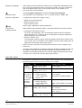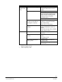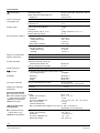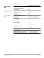
1
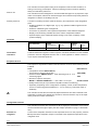
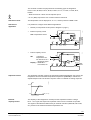
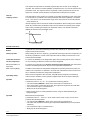
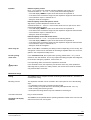
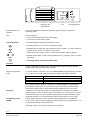
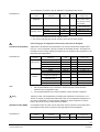
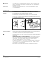
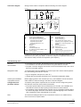
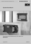
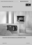
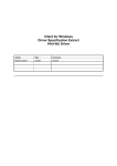
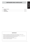
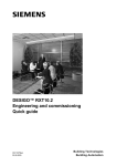
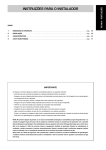
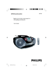
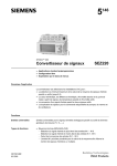
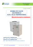
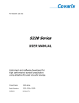
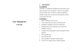
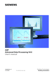
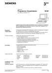
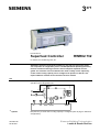
3 371 POLYCOOL™ Superheat Controller RWR62.732 for chillers, air conditioning units, etc. Standalone electronic superheat controller for use with any type of dry expansion evaporator in refrigeration plants. The MOP (Maximum Operating Pressure) function and the monitoring of sensors and of minimum superheat are integrated. The controller can be included in the chiller’s safety circuit. Optionally, control of the cooling capacity can be configured. It operates on AC 24 V. All required data are entered on the controller. No tools needed. Use 3371S02 The PolyCool™ superheat controller with its associated components ensures optimum operation of the refrigeration unit. EIV TM 1-4 p FG E1 * Options CE1N3371E 29.06.2001 AL Q1 X Y B3 Y1 p0 t0H B1 * * * t B2 KP B4 Y2 Required only if control of the cooling capacity is configured (refer to page 3 / Selection of application). Siemens Building Technologies Landis & Staefa Division Field of use Auxiliary functions The controller ensures optimum filling of the evaporator under all load conditions, resulting in low energy consumption. Various monitoring functions enhance operating safety and extend the plant’s live The controller has been designed for use with all standard types of dry expansion vaporators such as plate, tube and fin heat exchangers and is therefore especially suited for integration in chillers, air handling units, etc. A number of auxiliary functions enhance efficiency and supervision of the refrigeration plant: – Enabling operation via a digital input, e.g. by any operational status signal from the compressor – Selection of different types of refrigerants – Conversion of pressure to the respective temperature of the selected refrigerant – Display of all measuring variables and of the valve’s manipulated variable – Optional display of the superheat setpoint change in the case of capacity control (external display) Controller Type reference RWR62.732 Customized controllers Inputs Analog/binary 5 Outputs Analog Binary 2 3 Binary 2 Landis & Staefa also supplies customer-specific controllers that differ from the standard products in terms of refrigerant selection and / or outer appearance. Please contact us if you require customized products. Peripheral devices The PolyCool™ superheat controller uses two sensors* and one valve made by Landis & Staefa: Units Data sheet no. • Temperature sensor QAZ21.682/101 with a sensing element LG Ni 1000 Ω 1848 (OEM) • Pressure sensor QBE621-P10U-1...9 bar delivering a DC 0...10 V measuring signal 1905 • Electronic injection valve (EIV) M2FE..L.../MVL661-25/MVL661...-... with a DC 0..10 V input 4712/4713/4714 • Safety transformer (25 VA) to EN 60 742 (not included in the delivery) * Optionally, depending on the configuration of capacity control, another temperature sensor or external signal transmitter DC 0...10 V is used (e.g. POLYGYR Joker or UNIGYR) The controller and the above mentioned peripheral devices have been matched to the application covered by this data sheet. Therefore, valve and sensors may not be replaced by products of other manufacture. Configurable functions The controller's functions are preconfigured. By changing the parameters, the functions can be matched to the type of plant (see also chapter operation on page 7 «Parameter list»). Selection of refrigerant Control of the evaporator is based on true superheat control. For this purpose, pressure P0 acquired at the evaporator output is converted to the respective temperature of the refrigerant used. 2/14 Siemens Building Technologies Landis & Staefa Division Superheat Controller CE1N3371E 29.06.2001 The controller contains the polynomials of the following types of refrigerants: R 22, R 134a, R 404A, R 407c, R 507, R 290*, R 717**, R 1270*, R 410A, R 23, R 600a. * R290 und R1270 / valves are not explosion-proof! ** R 717 (NH3) requires the use of valves suited for ammonia! Selection of units The temperature can be displayed in °C or °F, and the pressure in BAR or PSI. Selection of application It is possible to configure three different applications: Default: pure superheat control (refer to diagram on page 1) • External capacity control 3371S03 • EIV - TM TM = temperature sensor UNIGYR 1-4 p E1 Q1 Internal capacity control KP B1 B2 TM = NI1000 or temperature sensor with DC 0-10 V measuring signal Display = UNIGYR or POLYGYR, etc. POLYGYR Joker etc. B4 Y2 EIV TM 1-4 p FG E1 AL Q1 X Y B3 Y1 t p0 t0H B1 B2 KP 0-10 V Display B4 Y2 The superheat controller monitors the temperature differential between the suction gas temperature and the calculated evaporation temperature (TOH-TO) to maintain the adjusted setpoint ∆T. The electronic injection valve is controlled via analog output Y1. 3371D02E Superheat control B3 Y1 0-10 V t p0 t0H - • X Y AL 3371S04 FG y EIV 100 % ∆T (T0H-T0) 0% ∆T SP Setpoint of superheat External capacity control The capacity of the refrigeration unit drops as the superheat increases. Using a DC 0...10 V signal, the setpoint of superheat control can be increased via input B4. The signal is calculated and delivered by an external controller (UNIGYR, POLYGYR, etc.), based on the measured medium temperature TM. 3/14 Siemens Building Technologies Landis & Staefa Division Superheat Controller CE1N3371E 29.06.2001 The setpoint of superheat is increased proportionally as a function of the voltage at input B4. The maximum increase (SMAX) corresponds to DC 10 V and is entered in the parameter mode. The setpoint used for superheat control represents the sum of the setpoint of overheat (∆T SP) entered in the parameter mode plus the increase. The temperature of the medium is acquired via input B4. Depending on the configuration of input B4, it is possible to choose a passive NI 1000 sensor (default) or an active DC 0...10 V sensor. The measurement range of the active sensor can be set between – 99.9 and 99.9 ºC Internal capacity control controls the medium temperature TM according to the setpoint (CAP. SP) entered in the parameter mode in that it reduces the capacity of the refrigeration unit by increasing the setpoint of superheat control. The maximum increase (SMAX) is entered in the parameter mode. 3371D04E Internal capacity control SMAX 0 TM 0 CAP. SP Setpoint medium temperature Standard functions Binary input E1 In general, the control and monitoring functions are enabled by an operational status signal received from the plant. When feeding an AC 24 V signal (e.g. operational status signal from the compressor) to the binary input E1, the control of the evaporator and the safety functions for the compressor will be activated. Protective functions for the compressor To ensure the reliability of the refrigeration plant and to prolong the life of the compressor, the following protective functions have been integrated: Minimum limitation of superheat To protect the compressor from shocks caused by liquid refrigerant, the valve will be closed in modulating mode when the minimum superheat falls below 2 K. MOP function [MOP] Limitation of the maximum evaporation temperature is another protective function provided for the compressor. It operates in PI mode and overrides the normal control function to maintain the maximum evaporation temperature. Operating safety When power is supplied to the controller, relay Q1 will be energized. The following actions protect automatic control operation against faults at the universal inputs (B.). Input B1 Measurement of pressure A measured value of ≤ 0 V or ≥ 10 V produces the following effects: – The LCD displays ERROR in place of the actual value of superheat ∆t – If the actual value crosses the range limit, the respective range limit value will flash – The controller’s output Y1 switches to 0 V – Relay Q1 will be de-energized * Enable * When returning to the normal operational values, relay Q1 will automatically be energized again. Input B2 Measurement of temperature A measured value of ≤ −35 °C or ≥ 90 °C means short-circuit or open-circuit, which produces the following effects: – The LCD displays ERROR in place of the actual value of superheat ∆t – The value of the measured suction gas temperature TOH flashes (one of the above extremes) – The controller’s output Y1 switches to 0 V – Relay Q1 will be de-energized * 4/14 Siemens Building Technologies Landis & Staefa Division Superheat Controller CE1N3371E 29.06.2001 Input B4 External capacity control DC 0...10 V signal from an external controller (UNIGYR, POLYGYR, etc.) A measured value of ≤ –0.5 V or ≥ 10.5 V produces the following effects: – The LCD displays ERROR in place of the actual value of superheat ∆t – If the actual value crosses the range limit, the respective range limit value will flash – The controller’s output Y1 switches to 0 V – Relay Q1 will be de-energized * Internal capacity control with passive sensor Signal from a passive temperature sensor NI 1000. A measured value of ≤ −35 °C or ≥ 90 °C means short-circuit or open-circuit, which produces the following effects: – The LCD displays ERROR in place of the actual value of superheat ∆t – If the actual value crosses the range limit, the respective range limit value will flash – The controller’s output Y1 switches to 0 V – Relay Q1 will be de-energized * Internal capacity control with active sensor A measured value of ≤ 0 V or ≥ 10 V produces the following effects: – The LCD displays ERROR in place of the actual value of superheat ∆t – If the actual value crosses the range limit, the respective range limit value will flash – The controller’s output Y1 switches to 0 V – Relay Q1 will be de-energized * Alarm relay Q1 Alarm contact Q1 is controlled by the safety functions. Depending on the circuitry, this changeover contact can be used either for actuating a separate alarm horn or for integration in the compressor’s safety circuit. Forced opening of the valve In the simulation mode, the required valve opening ( default value = 0 % ) can be entered on the user interface. This is very helpful when filling the plant with refrigerant, for short-time emergency operation, service work, etc. In this operating mode, the minimum superheat is monitored. Important In the simulation mode, the supervisory functions are active only if the operational status signal E1 is present. For safety reasons, the normal control mode is automatically resumed after 15 minutes. Mechanical design Casing The RWR62.732 is a compact controller conforming to DIN 43 880 Gr 1, housed in a closed plastic casing. Mounting choices The superheat controller can be mounted in the control panel in one of the following ways: • In a standard control panel conforming to DIN 43 880 • Wall mounting on top hat rails which are already fitted (EN 50 022 - 35 x 7.5) • Wall mounting with two fixing screws • Flush panel mounting with the help of the ARG62.10 mounting kit Connection terminals Plug-in screw terminals. Operating and display elements The RWR62.732 is operated with the operating elements located on the unit front. No aids such as a PC tool, are required. 5/14 Siemens Building Technologies Landis & Staefa Division Superheat Controller CE1N3371E 29.06.2001 Attach to Superheat EIV Y: Manipulated variable Y1 P0: Evaporation pressure relativ B1 T0: Evaporation temperature TOH: Suction gas temperature K INF0 B2 SEL 3371Z02e PolyCool Value ∆T: ⇑ Operating card compartement ⇑ LCD ⇑ Operating buttons Operating card compartment The card compartment contains the application-specific operating instructions (operating cards). LCD The LCD displays: • The current operational data (max. three digits) • The function code and the symbols Operating buttons The operating buttons provide the following functions: + • Operating buttons +/- are used to change flashing data - • Operating buttons INFO are used to select the screen. Button < is used to select the previous screen, button > to select the next screen. INF0 • When the screen changes, button > is also used to confirm a flashing display • Operating button SEL is used to change settings and, by pressing it again, to confirm SEL the change A flashing display indicates adjustable data. Operation For the configuration and fine tuning of the superheat controller, there are different operating levels and operating modes available. Selection of operating mode In normal operation, PolyCool™ is in the control mode. By simultaneously pressing the +/- buttons for a certain time, the required operating mode will be activated: Operating mode Activation time in seconds Parameter mode 5 Simulation mode 10 Configuration mode 15 If the controller has already been configured, the control mode will automatically be activated when switching on. From any other mode, the controller will automatically return to the control mode 15 minutes after pressing the INFO button on the right. Exception If settings in the configuration mode are changed while the controller is in operation (does not apply to units), controller output Y1 will switch to 0 V. In that case, the control will be released again only after all following parameters have been enabled by pressing the INFO button on the right (controller must be brought into the control mode). Configuration mode [CONF] Following the initial power up, the controller automatically enters the configuration mode. In this mode, the type of refrigerant is selected and the unit of temperature (°C or °F) and pressure (BAR or PSI) determined. Optionally, control of the cooling capacity can be configured. 6/14 Siemens Building Technologies Landis & Staefa Division Superheat Controller CE1N3371E 29.06.2001 To reconfigure the controller, refer to "Selection of operating mode" above. Parameter list Function Selection of refrigerant Unit Parameter Refrigerant SI or UN units Application Capacity control Type of sensor * Measurement range ** FunctionsCode Factory setting Selectable Range / step REFRIG - UNITS BAR / °C BAR / °C, BAR / °F, PSI / °F, PSI / °C NONE / EXT. / INT. R22, R134A, R404A, R407C, R507, R290, R717, R1270, R 410A, R 23, R 600a. CAP. NONE SENSOR NI1000 NI1000 / 0-10 V RANGE -35/35 °C -99.9....99.9 °C / 0.1 °C * Can only be selected with internal capacity control ** Can only be selected with internal capacity control and an active sensor If the wrong type of refrigerant is selected, the plant can be damaged! Parameter mode [PARA] Adjustment of all setpoints and parameters such as proportional band, integral action time, etc., for the superheat, capacity controller and the MOP function. The setpoint of the MOP function must be adjusted as specified by the supplier of the compressor or as demanded by the application. Function Parameter FunctionsCode Factory setting Selectable Range / step Superheat * Setpoint ∆T (t0H-t0) ∆T SP 7.0 K 4.0...16.0 K / 0.1 K P-band ∆T XP 10 K 2...200 K / 1 K Integral action time ∆T TN SEC 30 s 0...600 s (10 min) / 1 s Parameter list PID-sequence Note: Icing Simulation mode [SIMU] D-part ∆T D 0 0...5 MOP Max.limitation MOP SP 15.0 °C -35...35 °C / 0.1 °C P-band MOP XP 5.0 K 2...200 K / 1 K MOP TN SEC 30 s 0...600 s (10 min) / 1 s Capacity control ** Integral action time Maximum setpoint change with superheat Setpoint of medium temperature TM *** CAP. SMAX 18 K 0...50 K / 0.1 K CAP. SP 6 °C -35...90 °C / 0.1 °C P-band*** CAP. XP 35 K 2...200 K / 1 K Integral action time *** CAP. TN 95 s 0...600 s (10 min) / 1 s * ** The minimum overheat is fixed at 2.0 K and cannot be changed Can be parameterized only if external or internal capacity control has been selected in the configuration mode *** Can be parameterized only if internal capacity control has been configured Capacity control is accomplished by increasing the superheat. For this reason, a reduction in capacity is always associated with a drop in the evaporation temperature. In the case of chillers with no frost protection additives or direct expansion air coolers, there is thus a risk of icing under part load conditions. In simulation mode, the valve can be opened for service purposes. The position feedback signal and the values of pressure and temperature can be displayed. Parameter list Function Parameter FunctionsCode Factory setting Selectable Range / step Ventil manueller Öffnungssgrad EIV MAN V 0V 0...10 V / 0.1 V 7/14 Siemens Building Technologies Landis & Staefa Division Superheat Controller CE1N3371E 29.06.2001 Important! Control mode In simulation mode, the supervisory functions are active only if the operational status signal E1 is present. For safety reasons, the normal control mode is automatically resumed after 15 minutes. In this mode, all current input and output variables of the superheat and capacity control can be displayed. Installation notes For mounting and electrical installation, the following notes should be observed. Controller For mounting on DIN rails, no additional parts are required (A). For wall mounting, two screws for a hole diameter of 3.7 mm are required (B). For flush panel mounting (C) with the help of the Landis & Staefa ARG62.10 mounting kit / Mounting Instruction M 3351.1. A C B 49.5 ±1 ± 180 1 3351J06 3371Z09 Electrical installation The wiring can be made with standard cables. Shielded cables are recommended only if the controller is exposed to strong electromagnetic fields (EMC). The operating voltage must satisfy the requirements for safety extra low voltage (SELV) to EN 60 730. The transformers used must be safety transformers with double insulation conforming to EN 60 742. They must be designed for 100 % duty. When using several transformers in the system, terminals G0 must be galvanically interconnected. The PolyCool™ RWR62.732 controllers operate on AC 24 V (max. 10 A) extra low voltage and are short-circuit-proof. If voltages of more than AC 24 V are fed to the low voltage terminals, the controller or other connected devices can be damaged beyond repair. Also, voltages exceeding 42 V represent an electric shock hazard. Mains voltages up to AC 250 V may only be fed to the potential-free contact Q1. 8/14 Siemens Building Technologies Landis & Staefa Division Superheat Controller CE1N3371E 29.06.2001 Connection diagram Wiring must be made in compliance with the following connection diagram. B4 K1 B1 B M GL U1 M G E1 B4 M B1 M GO Y1 Y2 Q11 3371A02 3371A01 AC 24V B2 B M B2 B3 Q1 Q14 Q12 N1 Y1 1 G 3 Y G0 2 U 4 Display M1 H2 0 Units B1 B2 B4 H2 K1 M1 N1 Y1 Display Pressure sensor QBE621-P10U Temp. sensor QAZ21.682/101 Only if capacity control is configured: - temperature sensor passive - temperature sensor active - signal transmitter DC 0...10 V Horn (alarm) Enable Compressor Controller RWR62.732 El. expansion valve (EIV) M2FE.../MVL... Optional display (e.g. UNIGYR, POLYGYR, etc.) Terminals B1, M B2, M B3 B4, M Evaporation pressure Suction gas temp. Position feedback EIV Only required with capacity control: depending on the configuration, medium temperature or external signal DC 0...10 V E1 Release G, G0 Power supply AC 24 V Q11, Q12 Alarm (horn) Q11, Q14 Compressor safety circuit * Y1 Positioning EIV Y2 DC 0...10 V signal / proportional to the setpoint increase with superheat * If there is no pump down before switching off the unit, the evaporator pressure can raise above 9 bar (130.5 psi) relative. In this case, PolyCool Superheat should not be wired into the safety circuit of the compressor (see chapter 7). Commissioning notes Required documentation To commission the controller, the following pieces of documentation are required: • The Installation and User Manual CE1U3371X supplied with the controller • The plant connection diagram and all other control documentation kept in the control panel or by the plant operator Refrigeration data To configure the PolyCool RWR62.732 control loops and to set the relevant parameters, the following plant data are required: • Type of refrigerant used (R 22, R 134a, etc.) • Design data of evaporator (superheat, max. evaporation temperature, MOP) Checking the installation of peripheral devices Before applying power to the controller (AC 24 V), the installation must be checked to make certain it is wired according to the above connection diagram. Configuration and parameter settings To meet the plant-specific requirements, the controller must be configured by authorized staff who must also set the relevant parameters: • The project-specific data must be transferred to the controller. The Installation and User Manual contains the step-by-step procedure which must be followed • The operating cards supplied with the controller carry the application-specific data in the various languages. Place the cards with the required language in the controller’s card compartment. Enter changed data on the cards Note The values and settings entered on the controller are saved in non-volatile memory even in the event of a power failure. 9/14 Siemens Building Technologies Landis & Staefa Division Superheat Controller CE1N3371E 29.06.2001 Selection of refrigerant When starting up the controller for the first time, the configuration mode appears. First, the correct type of refrigerant and the units must be selected. The types of refrigerant that can be selected are: R 22, R 134A, R 404A, R 407C, R 507, R 290, R 717, R 1270, R 410A, R 23 and R 600a If the wrong type of refrigerant is selected, the plant can be damaged! Selection of units The temperature can be displayed in °C or °F, and the pressure in BAR or PSI. Selection of application Configurable are (also refer to pages 3 and 4): • Default: pure superheat control • External capacity control • Internal capacity control Icing Checking the peripheral devices Refer to page 7 (parameter mode /parameter list) Before switching the refrigeration plant on, the peripheral devices should be checked: • Temperature and pressure sensors The suction gas temperature TOH, the evaporation pressure P0, the evaporation temperature T0 and in accordance with the configuration, the medium temperature TM are displayed in the control mode • Electronic injection valve In the simulation mode, the degree of opening (MAN) of the electronic injection valve can be preset. Also, it is possible to check whether the valve's actual position (EIV X) agrees with the manually preset position (EIV Y) When the wiring of the plant and all peripheral devices are in order, the plant can be switched on. The factory-set parameters for superheat control (XP,TN and D), the MOP function and the capacity control (XP and TN) are values gained from practical experience. The Installation and User Manual CE1U3371X contains detailed information about how the controller can be fine-tuned to achieve optimum performance. Fault status signals Should faults or malfunctions on the controller, valve or sensors occur, the following list shows the possible causes and how the faults can be rectified: Component Passive temperature sensor NI1000 Active temperature sensor and other DC 0...10 V signal transmitters (UNIGYR, POLYGYR etc.) Pressure sensor Fault Measured value flashes Display: 90 °C / 194 °F Measured value flashes Display: -35 °C / -31 °F Measured value flashes: • Display depending on the configuration * • Display 0 V** Measured value flashes: • Display depending on the configuration * • Display 10 V** Measured value flashes Display: 9 bar / 131 psi Measured value flashes Display: -1 bar / -14.5 psi Possible cause / remedy Sensor cable with an open-circuit / not connected Sensor cable with a short-circuit Sensor cable with an open-circuit / not connected Faulty sensor / signal transmitter Faulty sensor / signal transmitter External noise voltage on the signal line Sensor cable with an open-circuit / not connected Measured value exceeds 9 bar / 131 psi Sensor cable with a short-circuit 10/14 Siemens Building Technologies Landis & Staefa Division Superheat Controller CE1N3371E 29.06.2001 Component Electronic injection valve (EIV) Controller * ** Fault No position feedback signal = 0V Possible cause / remedy Connecting cable for feedback signal with an open-circuit / not connected Valve does not open Connecting cable not connected In the simulation mode, the valve can be checked by manually entering the degree of opening and by comparing it with the position checkback signal Valve faulty Position feedback signal does Cable for feedback signal not connected (for connection terminals, not match the manually enrefer to data sheet) tered degree of opening Open-circuit or valve faulty Icing of evaporator when valve Valve faulty is closed Electronic calibration of valve not correct. Valve does not fully close; possibility of dirt inside the valve No display Check power supply (AC 24 V) Manipulated variable always Short-circuit / sensor with open0 V (Y1) circuit No enabling via E1 Controller faulty Icing of evaporator with no Controller output Y1 is not 0 V ➾ enabling via E1 Controller faulty External noise voltage on the signal line to the EIV External capacity control Internal capacity control 11/14 Siemens Building Technologies Landis & Staefa Division Superheat Controller CE1N3371E 29.06.2001 Technical data Operating voltage Safety extra low voltage (SELV) to Frequency AC 24 V ±20 % (Q1...Q6 AC 24...230 V) EN 60 730 50 Hz / 60 Hz Power consumption RWR62.732 5 VA Interrogation rate Cycle time Y1 0.5 s Cycle time Y2 1.5 s Display (LCD) Actual values and setpoints Resolution Analog outputs (DC 0...10 V) Binary switching outputs 3 digits 0.1 2 digits, resolution 0.1 V / 1 % off / on Environmental conditions Transport Climatic conditions Temperature range Humidity Mechanical conditions IEC 721-3-2 Class 2K3 -25...+70 °C < 95 % r.h. Class 2M2 Operation Climatic conditions Temperature range Humidity IEC 721-3-3 Class 3K5 -5...50 °C < 95 % r.h. Degree of contamination Normal contamination EN 60 730 Degree of protection Casing IP 20 to EN 60 529 Front Automatic electrical controls for household and similar use Energy management equipment IP 40 to EN 60 529 EN 60 730 UL 916 Production and customer service to ISO 9001 Power supply Product standards Quality assurance conformity Standards According to the directives of the European Union Low voltage directive 73/23/EEC Emissions Immunity Safety Connection terminals Plug-in screw terminals for wires Weight (excl. Packing) Controller Dimensions Refer to «Dimensions» Universal inputs B1-B4 B1 Pressure sensor (bar) B3 Position feedback signal valve(%)analog voltage *B4 Medium temperature *B4 External signal (*B4 According to the configuration) B2 Temperature sensor (LG Ni 1000 / 0 °C) *B4 Medium temperature EN 50 081-1 EN 50 082-1 EN 60 730 min.0.5 mm dia. 2 x 1.5 mm2 or 1 x 2.5 mm2 max. 0.40 kg Range DC 0...10 V Under- and overrange DC -1.4...11.4 V Resolution 1.0 mV Accuracy of RWR62.732 −0.2...+0 V at 0 V / −0.5...+0 V at 10 V Max. current drawn 0.11 mA Internal resistance Ri ≥ 100 kΩ Max. permissible cable length for dia. ≥0.6 mm 300 m, also refer to specification of connected unit Range Under- and overrange Resolution Accuracy of RWR62.732 Measuring voltage -35...130 °C -50...150 °C < 0.05 K at 0 °C −1K ...+0 K max. DC 5.0 V 12/14 Siemens Building Technologies Landis & Staefa Division Superheat Controller CE1N3371E 29.06.2001 Measuring current Max. permissible cable length for dia. ≥0.6 mm Binary control input E1, E2 2.6....3.4 mA 300 m (total line resistance of 4.5 Ω corresponds to an error of approx. 1 K) Sensing voltage for control commands Current drawn Max. permissible cable length for dia. ≥0.6mm AC 24 V ≤ 8 mA Voltage modulated (VM) Range Under- and overrange Resolution Max. current DC 0...10 V DC -1.4...11.4 V 15 mV ± 1 mA Binary switching output Q1 Switching capacity of relay contact Q1 Alternating current Direct current AC 24...230 V, 4 A res., 3 A ind. max. DC 50 V, max. 40 W, max. 5 A Min. contact rating At mains voltage At low voltage Max. starting current AC 230 V / 5 mA DC 24 V / 10 mA 10 A (1 s) 300 m Analog output Y1-Y2 Life of relay contacts AC at 0.1 A res. 2 . 107 cycles at 0.5 A res. 2 . 106 cycles 5 at 3 A res. 2 . 10 cycles Red. factor with inductive loads (cos.phi = 0.8) DC External fuse on input side Changeover switch Insulating strength Between relay outputs and low voltage (SELV) Between relay outputs and adjacent relays 0.85 2 . 105 cycles max. 10 A Q1 AC 3750 V, to EN 60 730 - 1 AC 3750 V, to EN 60 730 - 1 13/14 Siemens Building Technologies Landis & Staefa Division Superheat Controller CE1N3371E 29.06.2001 Dimensions 45 57 % K °F 90 73,5 °F 108 7,5 = 3,7 27,5 45 = % K 44 = 156 175 14/14 1999 Siemens Building Technologies AG Siemens Building Technologies Landis & Staefa Division Superheat Controller 68 52 72,5 3371M02 = EN 50 022-35 x 7,5 CE1N3371E 29.06.2001