1
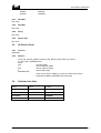
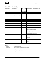
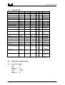
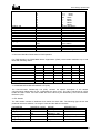
Citect for Windows
Driver Specification Extract
PROFIBD Driver
Author
Date
Comment
Matthew Dalton
20/3/97
Original
Driver Design Specification
Contents
3.
TARGET DEVICE(S) AND PROTOCOL
3.1 Introduction
4
3.2 Device Manufacturer
4
3.3 Device Definition
4
3.4 Communications Method
4
3.5 Communications/Hardware Configuration
5
3.5.1
Wiring Diagrams
5
3.5.2
I/O Device Settings
5
3.5.3
Software Setup (NT 4.0 only)
5
3.6 Special Requirements
6
3.6.1
Windows NT 4.0 version
6
3.6.2
Windows 95 version
6
3.7 Maximum Request Length
5.
4
USER INTERFACE
7
8
5.1 Introduction
8
5.2 Driver Name
8
5.3 Boards Form
8
5.3.1
Board Type
8
5.3.2
Address
8
5.3.3
IO Port
8
5.3.4
IRQ
8
5.3.5
Special Opt
8
5.4 Ports Form
8
5.4.1
Port Number
8
5.4.2
Baud Rate
8
5.4.3
Data Bits
9
5.4.4
Stop Bits
9
5.4.5
Parity
9
5.4.6
Special Opt
9
5.5 IO Devices Form
9
5.5.1
Protocol
9
5.5.2
Address
9
5.6 Pulldown lists Help
9
5.7 IO Device Variable Types
10
5.8 PROFIBD.DBF
11
PROFIBD.DOC
2
Driver Design Specification
5.9 Parameters and INI options
8.
11
5.9.1
Standard Parameters
11
5.9.2
Driver Specific Parameters
12
5.10
Driver Specific Errors
15
5.11
Driver Error Help
15
5.12
Debug Messages
15
5.13
Special Debugging Information
15
5.14
Stats Special Counters
16
5.15
Hints and Tips
16
REFERENCES
8.1 References
PROFIBD.DOC
17
17
3
Driver Design Specification
3.
3.1
Target Device(s) and Protocol
Introduction
This section defines the types of I/O Devices that are targeted by this driver.
3.2
Device Manufacturer
This is a generic driver for IODevice’s which support Profibus at FMS level. Examples of such
IODevices are S5, S7 and Weidmuller.
PROFIBUS-FMS is the general-purpose solution for communication tasks at the cell level. Powerful
FMS services open up a wide range of applications and provide great flexibility. PROFIBUS-FMS can
also be used for extensive and complex communication tasks.
3.3
Device Definition
The PROFIBD driver is designed to communicate to devices which support Profibus at the FMS level.
Since it is a upgrade version of PROFI driver, it supports all the devices which PROFI driver does.
PROFIBUS specifies the technical and functional characteristics of a serial fieldbus system with which
decentralized digital controllers can be networked together from the field level to the cell level.
PROFIBUS distinguishes between master devices and slave devices.
Master devices determine the data communication on the bus. A master can send messages without
an external request when it holds the bus access rights (the token). Masters are also called active
stations in the PROFIBUS protocol.
Slave devices are peripherial devices. Typical slave devices include input/output devices, valves,
drives and measuring transmitters. They do not have bus access rights and they can only
acknowledge received messages or send messages to the master when requested to do so. Slaves
are also called passive stations. Since they only require a small portion of the bus protocol, their
implementation is particularly economical.
3.4
Communications Method
Profibus is a token ring network running over a RS485 physical connection. The PROFIBUS network
corresponds to the German process and Fieldbus standard PROFIBUS DIN 19245. In PROFIBUSFMS, layers 1, 2 and 7 are defined. The application layer consists of FMS (Fieldbus Message
Specification) and LLI (Lower Layer Interface). FMS contains the application protocol and provides
the user with a wide selection of powerful communication services. LLI implements the various
communication relationships and provides FMS with device-independent access to layer 2. Layer 2
(FDL, Fieldbus Data Link) implements bus access control and data security. RS 485 transmission
technology or fiber optics are available for transmission for PROFIBUS-FMS.
RS 485 transmission is the transmission technology most frequently used by PROFIBUS. This
transmission technology is often referred to as H2. Its application area includes all areas in which high
transmission speed and simple inexpensive installation are required. Twisted pair shielded copper
cable with one conductor pair is used.
The RS 485 transmission technology is very easy to handle. Installation of the twisted pair cable does
not require expert knowledge. The bus structure permits addition and removal of stations or step-bystep commissioning of the system without influencing the other stations. Later expansions have no
effect on stations which are already in operation.
PROFIBD.DOC
4
Driver Design Specification
Transmission speeds between 9.6 kbit/sec and 12 Mbit/sec can be selected. One unique transmission
speed is selected for all devices on the bus when the system is commissioned.
Network topology Linear bus, active bus termination on both ends, stub lines only permitted for baud
rates of <= 500 kbit/sec. Shielding may be omitted depending on the environmental conditions (EMC).
32 stations are allowed in each segment without repeaters, up to 127 stations with repeaters.
Fiber optic conductors can be used for PROFIBUS for applications in environments with very high
electromagnetic interference and to increase the maximum distance for high transmission speeds.
Two types of conductors are available. Inexpensive plastic fiber conductors for distances <= 50 m or
glass fiber conductors for distances <= 1 km.
Many vendors offer special bus plug connectors with integrated conversion of RS 485 signals to fiber
optic conductors and vice versa. This provides a very simple method of switching between RS 485
transmission and fiber optic transmission within one system. See PROFIBUS guideline 2.022 for the
specification of the PROFIBUS-FO transmission technique.
3.5
Communications/Hardware Configuration
3.5.1
Wiring Diagrams
3.5.2
I/O Device Settings
See manual associated with specific device for detailed configuration information
3.5.3
Software Setup (NT 4.0 only)
The NT software for the PROFIboard card consists of a setup program which installs the Softing
drivers required.
To setup the PROFIBoard:
1. Start by installing the hardware card into the PC.
2. Logg on with Administrator rights.
3. Insert the “PROFIBoard NT” diskette into your diskette driver, if you have downloaded the files
from the Internet jump to point 5.
4. From the Start menu select “Run… ”
5. Type “A:\Install” or if you have the installation files on your harddisk, type in the path and the
filename to that location.
6. Click “OK”
PROFIBD.DOC
5
Driver Design Specification
Note! If you are unsure about the cards settings, choose “AutoConfig” during the installation.
After installation, make sure that the Softing PROFIboard is enabled in the Windows Control Panel /
Devices:
If you need to change the cards’IO area, you may change the 8 dip switches on the card. The DIP
switch have the following values:
Switch
Value
1
200hex
2
100hex
3
80hex
4
40hex
5
20hex
6
10hex
7
8hex
8
4hex
Default is (10010000) = 240hex.
The event log (viewed with the Event Viewer) will tell you what address and interrupt the PROFIboard
is set to. Make sure to copy the PAPI50.DLL file from the installation directory (defaults to \Program
Files\Profibus\Profiboard\PAPI\DLL) to the Citect\Bin directory.
3.6
Special Requirements
A Softing PROFIboard card is required to be installed in the Citect computer. The card is then
physically connected to the PROFIBUS network on which target PLCs resides.
This driver will only work on Windows NT 4.0
The client will need to purchase the ProfiBOARD and the software from Softing GmbH or Ci
Technologies.
3.6.1
Windows NT 4.0 version
Ordering information from Softing:
Hardware:
PB-IF-03
Software:
PROFI-DMK-NT (ver 5.11A)
3.6.2
Windows 95 version
A Windows 95 version of the PROFIBD driver is not available.
PROFIBD.DOC
6
Driver Design Specification
3.7
Maximum Request Length
2048 bits
PROFIBD.DOC
7
Driver Design Specification
5.
5.1
User Interface
Introduction
This section defines how the user will see the driver. This relates directly to how the Citect forms
need to be filled out and any special INI options. For the kernel, the debug trace messages and the
Stats.Special counters are documented.
5.2
Driver Name
PROFIBD
5.3
Boards Form
5.3.1
Board Type
PROFIBD
5.3.2
Address
0xD000 or 0xE000
Note! This value is sometimes referred to the same as above but with 4 zero’s, for example 0xD0000.
As the last zero is always a zero a common practise is to simply drop the last zero which gives
0xD000. This value is found in one of the events in the event viewer for the PROFIBoard, look at the
source “PROFIbrd”.
5.3.3
IO Port
Use the value which has been set on the Softing card. See section 3.5.3 for details on the DIP
switches.
e.g.:
0x240
5.3.4
IRQ
Not Used
5.3.5
Special Opt
Not Used
5.4
Ports Form
5.4.1
Port Number
Not Used
5.4.2
Baud Rate
9.6 Kbit/s - 12Mbit/s (select one according to the specific devices)
Transmission Rate
Citect Entry
9.6 Kbit/s
9600
19.2 Kbit/s
19200
93.75 Kbit/s
93750
187.5 Kbit/s
187500
500 Kbit/s
500000
1.5 Mbit/s
1500000
3 Mbit/s
3000000
PROFIBD.DOC
8
Driver Design Specification
6 Mbit/s
12 Mbit/s
5.4.3
6000000
12000000
Data Bits
Not used
5.4.4
Stop Bits
Not used
5.4.5
Parity
Not used
5.4.6
Special Opt
Not used
5.5
IO Devices Form
5.5.1
Protocol
PROFIBD
5.5.2
Address
Local_sap Remote_address Remote_Seg Remote_lsap Name_Of_Device
e.g 128 1 255 4 WEIDMULLER
where
128
local sap (lsap)
1
remote address (raddr)
255
remote segment (rseg)
4
remote sap (rlsap)
WEIDMULLER
name of the section heading in Citect.ini under where all the
parameters related to WEIDMULLER will be put)
5.6
Pulldown lists Help
TYPE
DATA
BOARDTYPE
PROFIBD
PROTOCOL
PROFIBD
FILTER
ADDRESS
PROFIBD
IOPORT
PROFIBD
PROFIBD.DOC
9
Driver Design Specification
5.7
IO Device Variable Types
IO Device Type
Citect data type
Citect
type
INTEGER
arrays
<index>[/<sub index>[.bit]]
DIGITAL, INT,
LONG, REAL,
BYTE, STRING
READ/WRITE
B
B<index>[/<sub index>[.bit]]
BYTE
READ/WRITE
R
R<index>[/<sub index>[.bit]]
REAL
READ/WRITE
L
L<index>[/<sub index>[.bit]]
LONG
READ/WRITE
BWR
BWR<index>
REAL
Block Write Array Native
BWL
BWL<index>
LONG
Block Write Array Native
BW
BW<index>
INTEGER
Block Write Array Native
SL
SL<index>
STRING
String with size set by read length
S
S<len>:<index>
STRING
String with size set by user
S32TM
S32TM<index>
STRING
32 bit Profibus time/date format.
S48DIF
S48DIF<index>
STRING
Format- HH:MM:SS.MSMSMS e.g. 12:34:56.000
48 bit Profibus time difference
S48DT
S48DT<index>
STRING
Format- HH:MM:SS.MSMSMS e.g. 33:33:33.000
48 bit Profibus date only format
S48TMDT
S48TMDT<index>
STRING
Format- DD:MM:YYYY e.g. 10:11:1999
48 bit Profibus time date format
STRING
FormatD:MM:YYYY HH:MM:SS.MSMSMS
e.g. 10:11:1999 12:34:56.000
48 bit Unigyr date only format
(16bit)
SU48DT
SU48DT<index>
data
Description/Special Usage/Limitations/ Valid
Ranges
FormatEither Yearless date (DD.MM) or DD:MM:YYYY
HH:MM:SS.MSMSMS or DD:MM:YYYY
32 bit Profibus time/date format (without
milliseconds).
SU32TM
S32TM<index>
STRING
SU48DIF
S48DIF<index>
STRING
Format- HH:MM:SS e.g. 12:34:56
48 bit Profibus time difference
milliseconds)
(without
SU48TMDT
S48TMDT<index>
STRING
Format- HH:MM:SS e.g. 33:33:33
48 bit Profibus time date format
milliseconds)
(without
FormatD:MM:YYYY HH:MM:SS
e.g. 10:11:1999 12:34:56
Where:
<index>
A valid variable index
<sub index>
index of the array element required (1 to 255)
<bit>
Bit specifier for DIGITAL variables
<len>
Wite length to specify in the protocol request when
writing this type to the PLC
PROFIBD.DOC
10
Driver Design Specification
5.8
PROFIBD.DBF
TEMPLATE
%F[.%u(0,0,15)]
%F/%U(0,1,255)[.%u(0,0,15
)]
B%F[.%u(0,0,15)]
UNIT_TYPE
0x00000
0x10000
RAW_TYPE
1
1
BIT_WIDTH
16
16
LOW
0
0
HIGH
0
0
COMMENT
Simple variables
Array variables
0x20000
8
8
0
0
B%F/%U(0,1,255)[.%u(0,0,
15)]
R%F
0x30000
8
8
0
0
Simple
Native
Byte
Array Native Byte
0x00000
2
32
0
0
R%F/%U(0,1,255)
L%F
0x10000
0x00000
2
4
32
32
0
0
0
0
L%F/%U(0,1,255)
BWR%F/%U(0,1,255)
0x10000
0x50000
4
2
32
32
0
0
0
0
BWL%F/%U(0,1,255)
0x50000
4
32
0
0
BW%F/%U(0,1,255)
0x50000
1
16
0
0
SL%F
0x60000
7
1024
0
0
S32TM%F
0x70000
7
200
0
0
S48DIF%F
0x80000
7
200
0
0
S48DT%F
0x90000
7
200
0
0
S48TMDT%F
0xA0000
7
200
0
0
S%<24(0,1,256):%F
0xB0000
7
1024
0
0
SU48DT%F
0xC0000
7
200
0
0
SU32TM%F
0xD0000
7
200
0
0
SU48DIF%F
0xE0000
7
200
0
0
SU48TMDT%F
0xF0000
7
200
0
0
5.9
Parameters and INI options
5.9.1
Standard Parameters
Block
Delay
MaxPending
Polltime
Timeout
Retry
WatchTime
PROFIBD.DOC
Simple
Native
Real
Array Native Real
Simple
Native
Long
Array Native Long
Block
Write
Array Native
Block
Write
Array Native
Block
Write
Array Native
String with size
set
by
read
length
32 bit Profibus
time/date format
48 bit Profibus
time difference
48 bit Profibus
date only format
48 bit Profibus
time date format
String with size
set by user
48 bit Unigyr
date only format
32 bit Profibus
time/date format
without
milleseconds
48 bit Profibus
time difference
without
milleseconds
48 bit Profibus
time date format
without
milleseconds
128
0
4
10 ms
4000 ms
2
30
11
Driver Design Specification
5.9.2
Driver Specific Parameters
[PROFIBD]
window
Local_Address
Local_Segment
Tsl
Min_Tsdr
Max_Tsdr
Tqui
Tset
Ttr
G
In_Ring_Desired
Hsa
Max_Retry_Limit
Poll_Sap
Symbol_Length
Ass_Abt_Ci
[<unit>]
Display the profibus debug window
Address of this station on the PROFIBUS network
Segment for this station on the PROFIBUS network
Slot Time
Minimum Station Delay Time
Maximum Station Delay Time
Quiet Time
Setup Time
Desired Target Rotation Time
Gap update factor
This station must be in the token ring
Highest station Address on the PROFIBUS network
Number of Retries performed
Sap used for poll list processing
Max length of connection names
Timeout for associate and abort Services in 10ms intervals
Max_Rcc
Max_Sac
Max_Rac
Ci
(<unit> = Name_of_Device field from IODevice | address), one topic per
IODevice
Number of outstanding reuqest a unit can handle. This must be less than or
equal to Max_Scc and greater than 0
A Valid index to read as a test of the comms link. Used for Citect redundency.
“MMAC” master async, or “MSAC” slave async depending if the device is a
master (token holder) on the PROFIBUS networkor not.
Max number of confirmed requests sent. The PROFIB driver reuqires at least
one of these ie Max_Scc = 1.
Max number of confirmed indications received.
Max number of unconfirmed requests sent.
Max number of unconfirmed indications received.
Control interval, time (x 10ms) Citect requires 0 ie no checks made.
Max_Pdu_Snd_High
Max_Pdu_Snd_Low
Sent PDU sizes must be less than or equal to the destination device receive
PDU sizes.
Max_Pdu_Rcv_High
Max_Pdu_Rcv_Low
Receive PDU sizes must be greater than or equal to the destination devices
send PDU sizes.
Feature_Support_0
Feature_Support_1
Feature_Support_2
These relate to the services supported by the destination device as a server.
Citect requires support for READ and WRITE services. The device is a server
and Citect the client. (NOTE! Entered as DECIMAL values, not HEX)
Feature_Support_3
Feature_Support_4
Feature_Support_5
These relate to the services supported by the destination device as a client.
Citect does not support any services as a server. Therefore the client
services required are all normally disabled (set to zero). (NOTE! Entered as
DECIMAL values, not HEX)
MaxOutStanding
TestIndex
Conn_Type
Max_Scc
BUS PARAMETERS
1. Range of Values
The following figure lists all Bus Parameters with their definition and the range of value.
PARAMTER
RANGE OF VALUE
DESCRIPTION
loc_add
loc_segm
baud_rate
PROFIBD.DOC
0..126
0..63
255
0
local station address
local segment address
no segment address
9.6
Kbit/s
12
Driver Design Specification
medium_red
tsl
min_tsdr
max_tsdr
tqui
tset
ttr
g
in_ring_desired
hsa
max_retry_limit
ident
19.2
Kbit/s
93.75
Kbit/s
187.5
Kbit/s
500
Kbit/s
1.5
Mbit/s
3
Mbit/s
6
Mbit/s
12
Mbit/s
no bus redundancy
slot time
min station delay time
max station delay time
quiet time
setup time
target rotation time
gap update factor
passive station
active station
highest station address
max retry limit
FDL ident string
1
2
3
4
6
7
8
9
0
37..16383
11..1023
35..1023
0..127
1..479
256..16777215
1.255
0
255
1..126
0..7
2. Recommended Bus Parameters for FMS Operation
For FMS-operation the PROFIBUS Nutzer Organization (PNO) recommends baudrates up to 500
Kbit/s with following values:
baudrate (Kbit/s)
tsl
min_tsdr
max_tsdr
tset
tqui
ttr
g
hsa
max_retry_limit
9.6
100
30
50
5
22
10000
1
126
1
19.2
200
60
100
10
22
15000
1
126
1
93.75
500
125
250
15
22
30000
1
126
1
187.5
1500
250
500
25
22
50000
1
126
1
500
3000
500
1000
50
22
100000
1
126
1
1500
-
3. COMMUNICATION RELATIONSHIP LIST (CRL)
The Communication Relationship List (CRL) contains the specific description of all network
communication relationships of FAL, independent the time of use. The CRL is structured as a CRL
header and CRL entries. The CRL header and each CRL entry are identified by the Communication
Reference (CR).
4. CRL Header
The CRL header consists of attributes which define the whole CRL. The following figure shows the
parameter with their definition, the range of value and the defined constants.
PARAMETER
nr_of_entries
poll_sap
symbol_length
ass_abt_ci
vfd_pointer_supported
PROFIBD.DOC
RANGE OF VALUE
0..128
0,2..61
128
0.32
1..4294967295
0
DEFINE
0..MAX_COMREF
DEFAULT_SAP
0..CRL_SYMBOL
PB_FALSE
DESCRIPTION
number of CRL entries
poll list SAP
length of CRL symbol
ASS/ABT control interval
one VFD supported
13
Driver Design Specification
255
PB_TRUE
multiple VFDs supported
5. CRL Entry
The CRL entry contains the complete description of the station’s communication relationships. The
following figure lists the parameters with their definition, the range of value of value and the defined
constants.
PARAMETER
loc_lsap
rem_add
rem_segm
rem_lsap
conn_type
LLI_sap
multiplier
conn_attr
max_scc
max_rcc
max_sac
max_rac
ci
max_pdu_snd
_high
max_pdu_snd
_low
Max_pdu_rcv_
high
Max_pdu_rcv_
low
Feature_supp
Sumbol
Vfd_pointer
Extension
RANGE OF VALUE
0..62
63
128
0..124
127
255
0..63
255
0..62
63
128
255
(see below)
0
1
0..255
(see below)
0..20
0..20
0..20
0..20
0..232-1
0..241
0..241
0..241
0..241
16-1
0..2
DEFINE
DESCRITION
local SAP
BRCT_SAP
DEFAULT_SAP
GLOBAL_ADDR
ALL
remote station address
used for Broadcast
remote segment address
NO_SEGMENT
remote SAP
BRCT_SAP
DEFAULT_SAP
ALL
(see below)
FMS_SAP
FM7_SAP
(see below)
connection type
LLI SAP for FMS
LLI SAP for FM7
multiplier on cyclic connections
connection attribtue
max send confirmed counter
max receive confirmed counter
max send acknowledge counter
max received acknowledge counter
control intervall
max FMS/FM7 PDU length send
high
max FMS/FM7 PDU length send low
max FMS/FM7 PDU length receive
high
max FMS/FM7 PDU length receive
low
supported FMS/FM7 features
symbolic name
vfd number
extention
CITECT.INI example for a single Weidmuller system (Note! Multiple IODevices require unique entries
in the CITECT.INI)
[profibd]
debugstr=* all
window=1
LOCAL_ADDRESS=3
LOCAL_SEGMENT=255
POLL_SAP=128
LOG=1
[WEIDMULLER]
MaxOutstanding=1
TestIndex=40
conn_type="MSAC"
PROFIBD.DOC
14
Driver Design Specification
Max_pdu_snd_high=0
Max_pdu_snd_low=49
Max_pdu_rcv_high=0
Max_pdu_rcv_low=241
Ci=0
5.10
Driver Specific Errors
See section 5.12
5.11
Driver Error Help
NONE
5.12
Debug Messages
Driver Errors
format: 0xAAIIRRRR
where
AA - Area
ERROR_OTHER
ERROR_TIMEOUT
ERROR_REC
ERROR_SND
ERROR_FM7_NEG
ERROR_FM7_ABORT
ERROR_FM7_EVENT
ERROR_FMS_NEG
ERROR_INITIATE
ERROR_ABORT
ERROR_UNKNOWN_SERVICE
II - Instance of the code
Instance Id codes:
USR
LLI_USR
LLI
FDL / FMA2
0x00
0x01
0x02
0x03
0x04
0x05
0x06
0x07
0x08
0x09
0x0a
0
1
2
3
RRRR -Reason for Error
Too many to be listed here, see manual for the detailed information.
5.13
Special Debugging Information
The Profibus Debug Window
This window is an important aid in debugging connections to a device. To activate the window set the
following Citect INI parameter:
[PROFIBD]
window=1
The output displays the services requested from the lower level PROFIBUS interface and the
responses. Many of the PROFIBUS network and connection parameters are displayed so that they
can be checked as the driver attempts to make a connection. Error information is also displayed.
The debugging window supports the key command D to toggle the display on / off. And the key L to
toggle logging the same output to a file as described below.
PROFIBD.DOC
15
Driver Design Specification
The information from the debug window can be logged to file. This is only recommended for testing as
it may make Citect unstable. To log to file:
n Create an empty text file called PROFIBD.LOG in a directory called C:\WINDOWS.
n Add the entry [PROFIBD]LOG=1 to the Citect INI file.
n Start Citect
5.14
Stats Special Counters
NONE
5.15
Hints and Tips
i) On the PROFIBoard there is a small green lamp which should go on when Citect runtime starts up
and it should go off when Citect runtime is shutdown.
ii) If you get no errors in the Event Log at startup but Citect “hangs” when it tries to initialize the card
you may have a hardware conflict. Remove all other hardware’s in the PC and try again.
iii) Installation Hints for RS 485
Transmission
All devices are connected in a bus structure (i.e., line). Up to 32 stations (master or slaves) can be
connected in one segment. The bus is terminated by an active bus terminator at the beginning and
end of each segment. To ensure error-free operation, both bus terminations must always be powered.
Many vendors have designed a switchable bus termination in their devices or plug connectors. When
more than 32 stations are used, repeaters (line amplifiers) must be used to connect the individual bus
segments.
The maximum cable length depends on the transmission speed. See the table below. The specified
cable length can be increased by the use of repeaters. The Use of more than 3 repeaters in series is
not recommended.
Baud rate (kbit/sec)
9.6
19.2
93.75
187.5
500
1500
12000
Distance/segment
1200 m
1200 m
1200 m
1000 m
400 m
200 m
100 m
When connecting the stations, make sure that the data lines are not twisted. Use of shielded data
lines is absolutely essential to the achievement of high system immunity in environments with high
electromagnetic emissions (e.g., automobile manufacturing). Shielding is used to improve
electromagnetic compatibility (EMC). The shield braiding and, if present, the shield foil should be
connected to protective ground on both sides and with good conductivity via shield clamps covering
as large an area as possible. In addition, it is recommended that the data lines be kept separate from
all high-voltage cables.
Stub lines should be avoided for data transmission speeds of more than 500 kbit/sec. Plug connectors
available on the market permit the incoming data cable and the outgoing data cable to be connected
directly in the plug connector. This means that stub lines do not have to be used, and the bus plug
connector can be connected and disconnected at all times without interrupting data communication
with the other stations.
PROFIBD.DOC
16
Driver Design Specification
8.
8.1
References
References
PROFIBUS Application Program Interface
User Manual Version 5.0 Rev. 03 31/1/96
Softing GmbH
PROFIBD.DOC
17