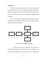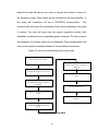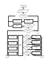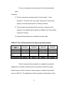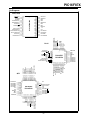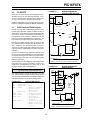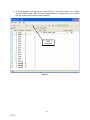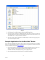
1
OBSTACLE DETECTION FOR A SPEECH-CONTROLLED DC MOTOR OPERATED WHEELCHAIR WITH ELEVATION SYSTEM By Lloyd Edwinson S. Arellano Darryll Jade E. Arias Francis Mark Adriane G. Luna Aljon C. Santillan A Thesis Report Submitted to the School of Electrical Engineering, Electronics Engineering, and Computer Engineering in Partial Fulfillment of the Requirements for the Degree Bachelor of Science in Computer Engineering Mapúa Institute of Technology March 2012 i ii TABLE OF CONTENTS TITLE PAGE i APPROVAL SHEET ii TABLE OF CONTENTS iii LIST OF TABLES iv LIST OF FIGURES v ABSTRACT vi CHAPTER 1: INTRODUCTION 1 CHAPTER 2: REVIEW OF RELATED LITERATURES AND RELATED STUDIES 4 Speech Recognition Infrared Proximity Sensor Direct Current (DC) Motors Battery Assisted Wheel Chair Voice Controlled Automation System A Survey and Experimental Evaluation of Proximity Sensors for Space Robotics Switchgear control apparatus and relays for alternating-current circuits Obstacle Avoidance Fuzzy System for Mobile Robot with IR Sensors 4 5 6 7 7 9 9 10 CHAPTER 3 OBSTACLE DETECTION FOR A SPEECH-CONTROLLED DC MOTOR OPERATED WHEELCHAIR WITH ELEVATION SYSTEM 12 Abstract Introduction Methodology 12 12 13 CHAPTER 4: CONCLUSION 31 CHAPTER 5: RECOMMENDATION 33 BIBLIOGRAPHY 34 APPENDICES Appendix Appendix Appendix Appendix 35 A. User’s Manual B. Pictures of Prototype C. Program Listing D. Data Sheets 35 38 40 iii LIST OF TABLES Table 3.5 Test of effectiveness of the front and back proximity sensors Table 3.6 Test of effectiveness of the bottom proximity sensors Table 3.7 Measurement of distance in obstacle detection Table 3.8 Measurement of the response time in performing the movement command Table 3.9.A Determination of the obstacles that can be detected by front and back sensors Table 3.9.B Determination of the obstacles that can be detected by bottom sensors iv LIST OF FIGURES Fig 3.1 Conceptual Framework of the study Fig 3.2 Methodology Block Fig 3.3.A Speech Recognition Module Flowchart Fig 3.3.B Speech Recognition Algorithm Fig 3.4.A Elevation System Flowchart Fig 3.4.B Elevation System Algorithm Fig 3.5.A Obstacle Detection Flowchart Fig 3.5.B Obstacle Detection Algorithm v Abstract Nowadays, most handicapped people who suffer mobility problem primarily depend on using wheelchairs and most of these wheelchairs are already automated. The designs are made in response to the condition of the target user. Considering the users who already lost the ability to use their hands, the researchers of this paper believe that implementing a speech control mechanism and incorporating sensors to the wheelchair will give solution to this problem. It is also believed that to improve its functionality, a lifting mechanism should be considered to allow the user to move up by himself into elevated platforms. As a result, an obstacle detection for a speech controlled dc-operated wheelchair with elevation system is considered in this paper. The wheelchair will use voice module that will process the user input speech command and a microcontroller to control the movement of the wheelchair in response to the user input command. Proximity sensors will also be used to create a system wherein obstacle detection mechanism is present. Lastly, for the elevation system the wheelchair will be incorporated by an electric car jack that will allow itself to lift into the elevated platform. Keywords: Voice module, Electric car jack, PIC microcontroller, DC motors,Proximity Sensors vi Chapter 1 INTRODUCTION Wheelchairs are one of the commonly used devices for assisting human mobility. It was invented as a solution to the mobility problems of paralytic people. Most of these people are those who suffer serious cases and totally lost their mobility. An ordinary wheelchair is a big help to them but still needs another person for assistance. Nowadays, there are various types of wheelchairs that already exist. Some of the innovations made the manually operated wheel chair into an automated system. The most common type of automated wheelchair is the one controlled through buttons and joysticks. Other designs implement some advance technology such as wireless application and voice recognition to improve the existing wheelchair designs. These wheelchairs are generally prescribed for those people who experience difficulty in using manual wheelchair due to arm and other disabling conditions. The condition of the user indicates the type of electronic wheelchair to be used. For some cases, when the user lacks coordination with his finger, hand controlled wheelchair would not be advisable. Other means of controls must be implemented for the convenience of the patient. Although there are a lot of studies regarding the improvement of a wheelchair, most of these are concentrating on the application of easier manual control or voice recognition alone and do not give more concern on the safety of 1 the users. Most of them do not have the ability to elevate the wheelchair and thus make it less reliable when the user goes to different places alone. This study aims to design an obstacle detection mechanism for a speech controlled wheelchair with elevation to improve safety of users. The specific objectives of this study are the following: a) To design an obstacle detection mechanism using proximity sensors b) To specify possible obstacles that the wheelchair can detect c) To determine the effectiveness of proximity sensors when used for obstacle detection. With the completion of this study, people who are having problems with mobility will have fewer worries when it comes to their safety in using a wheelchair. They will also have the benefit of using a speech recognition wheelchair that would allow them to manipulate the direction where they would like to go and can elevate themselves to a certain level without using physical strength. The obstacle detection mechanism comprises of proximity sensors that can be activated to avoid accidents like falling down from a gutter and hitting a wall. Speech recognition technology is applied to the wheelchair. There will be a headset to be worn by the user to serve as his medium of control for the device. There are also 2 emergency buttons; one for stop and another one for enabling and disabling the obstacle detection system. The wheelchair will consist of 7 commands, namely, move forward, move backward, move left, move right, stop, move up (to elevate), and move down. The headset will receive voice command 2 from the user to determine the movement of the wheelchair and even allow it to be elevated upon command. For instance, the user says “move-forward”, the voice command will trigger the forward movement of the device. Similarly, there will be another voice command for the wheelchair to turn either to the right or left direction and to elevate or not. The input command from the headset will be transmitted to the microcontroller through wires. The microcontroller will be responsible in processing the input from the user. DC motors will be applied on the wheel chair as well as relay drivers. The DC motors will serve as the main machine in moving the device. The power will then be supplied by batteries. On the other hand, the relay drivers will be used to supply enough power to the motors. The microcontroller itself is not capable of providing the needed power of the motors. The use of wheelchair is limited due to the source of power which is a battery. The wheelchair can only perform one movement operation at a time and has a stable speed. People who are mute cannot use the wheelchair. The wheelchair has a limit on how high it can elevate and is mostly used only for sidewalk banks. The design cannot elevate on stairs due to simultaneous elevation. The obstacle mechanism can only detect large obstacle like walls and can also detect near falling off platform. When the obstacle detection system detects an obstacle it will then make the wheelchair to immediately stop automatically. To enable the elevation, the user must first disable the obstacle mechanism. 3 CHAPTER 2 REVIEW OF RELATED LITERATURE For the past decades, evolution of ways to improve technology that will support people with mobility problems has been given a lot of attention. Because of the latest trend of technology, people were able to communicate with machines through programs. Speech is a natural mode of communication for people and with the use of the latest technology, people have created speech recognition programs. Speech Recognition Speech recognition, often called automatic speech recognition, is the process by which a computer recognizes what a person says. Speech recognition is the ability of a machine or program to identify words and phrases in spoken language and convert them to a machine-readable format. However, rudimentary speech recognition software has a limited vocabulary of words and phrases and may only identify them if they are spoken very clearly. More sophisticated software has the ability to accept natural speech. Speech recognition applications include call routing, speech-to-text, voice dialling, and voice search. Speech recognition software has two primary components. The first piece, called the acoustic model, analyzes the sounds of the voice and converts them to phonemes, the basic elements of speech. The second major component of speech recognition software is the language model which analyzes the content of the speech. It compares the combinations of phonemes to the words in its 4 digital dictionary (Miastkowski, 2000). The structure of a standard speech recognition system is illustrated in the figure below: Infrared Proximity Sensor Infrared proximity switches work by sending out beams of invisible infrared light. A photodetector on the proximity switch detects any reflections of this light. These reflections allow infrared proximity switches to determine whether there is an object nearby. Proximity switches with just a light source and photodiode are susceptible to false readings due to background light. Thus, more complex switches modulate the transmitted light at a specific frequency and have receivers which only respond to that frequency. Proximity sensor captures the reflected infrared signal. The proximity readout is linearly proportional to the captured infrared-light signal intensity and inversely proportional to the square of the distance (Luo & Schmitz, 2009). 5 Different types of proximity sensors can be used but Infrared Proximity sensors would be the best choice because of their sensitivity. Direct Current (DC) Motors In any electric motor, operation is based on simple electromagnetism. A current-carrying conductor generates a magnetic field; when this is placed in an external magnetic field, it will experience a force proportional to the current in the conductor, and to the strength of the external magnetic field. The internal configuration of a DC motor is designed to harness the magnetic interaction between a current-carrying conductor and an external magnetic field to generate rotational motion. At a simplistic level, using DC motors is pretty straightforward; put power in, and get rotary motion out (Seale, 2003). DC motors are used on the design as a source of power in elevation and movement of the wheelchair. 6 Related Studies Battery Assisted Wheel Chair This research deals with series hybrid combination of manual and battery powered wheelchair. The control scheme used is simpler than other hybrid wheelchairs. It includes the sensor less control of the speed. Battery assisted wheelchair (BAW) which is operated by a DC motor and has less number of components in its hardware. Effort made by rider is reduced considerably. The control scheme also includes the dead man’s switch feature. Speed loop is provided for the smooth variation of the speed. The current limit is governed by peak current mode control (Rahulanker & Ramanarayanan, 2006). Voice Controlled Automation System This paper discusses speech recognition and its application in control mechanism. Speech recognition can be used to automate many tasks that usually require hands-on human interaction, such as recognizing simple spoken commands to perform something like turning on lights or shutting a door or driving a motor. Despite these breakthroughs, however, current efforts are still far away from a 1000/0 recognition of natural human speech. Therefore, the project is considered but it involves processing of a speech signal in any form as a challenging and rewarding one. In this paper, a block diagram was used to show the sequence on how speech will be processed. 7 Pattern matching was also discussed and was stated that the comparison of two speech signals is nothing but basically their pattern matching. The speech signal can be represented as the set of numbers representing certain features of the speech that is to be described. For further processing, it is useful to construct a vector out of these numbers by assigning each measured value to one component of the vector. It is also stated that an uttered voice can differ from a stored template due to interference, noise, and other magnitude distortions which corrupt the input signal and can make it sound different from the reference signal. Also, unexpected pauses, unusually fast or slow speaking styles, and other changes in speed can randomly shift the position of the input relative to the template. The same person can utter the same word in slightly different ways each time. The person can pause, speak faster, speak slower, or emphasize certain syllables. These differences are called intra-speaker differences. The differences between the same words uttered by the different speakers or different words uttered by same speaker or different speakers are called inter-speaker differences. These differences are large as compared to intra speaker differences (Haleem, 2008). 8 A Survey and Experimental Evaluation of Proximity Sensors for Space Robotics The paper provides an overview selection process for proximity sensors for manipulator collision avoidance. Five categories of sensors have been considered for this use in space operations: intensity of reflection, triangulation, time of flight, capacitive, and inductive. From these categories, the most promising commercial and mature laboratory prototype sensors have been selected and tested. After reviewing the selection process and the experimental results, conclusions are drawn about which sensors are best and why. The report has detailed the selection of proximity sensors for manipulator collision avoidance. In this paper proximity sensors were tested and their capabilities were known. Optical intensity of reflection sensors are probably the most widely available in the number of manufacturers, the number of models, and the ranges of operation. Many of these sensors have adjustable ranges, which are set by turning a potentiometer on the sensor housing. Therefore, the ranges listed for some sensors may not be attainable by one sensor setting (Volpe & Ivlev, 1994). Switchgear control apparatus and relays for alternating-current circuits The paper stated that control relays are a standard practice for a correct design and it is very important to lay-out such relays in the circuit. With this, the system depends on the proper action of relays because this will take a large part on the success of the operation of circuit. Implementing relays to control a circuit 9 requires that the circuit must be controlled by only one signal. Multiple relays can be activated at the same time, thus a different operation must be done with single activated relay; different combinations can have different operations. In the article, relays are used to control the alternating currents of a switchgear control apparatus. The relay here has a single moving element which moves under the action of the currents. The team also stated that if the circuit is in breakdown, the overload on the single overloaded phase must be much greater than before for the relay to operate. This means that if the circuit has no relays the overloading will occur simultaneously on each of the operation phases but if relays are installed, this overloading will only occur in only one phase, thus make the circuit safe for more damage that it will take from breakdown (Garrard, 2010). Obstacle Avoidance Fuzzy System for Mobile Robot with IR Sensors The paper deals with the navigation problem of mobile robots in an unknown indoor environment with the use of infrared sensors. In this paper, the robot has the ability to plan motion and to navigate autonomously avoiding any type of obstacles. This is a reactive strategy and is completely based on sensory information. This gives the idea that infrared sensors can be used as proximity sensors for an obstacle detection mechanism. It has been stated in the article that infrared detectors have built-in optical filters that allow very little light which is the main idea of detecting an obstacle whether it is physically present or not. 10 By using infrared sensors, a program can be designed for obstacle detection and thus allow the possibility of creating a machine that would be used for collision avoidance. This article proves that a collision free navigation system is possible in a machine that uses infrared sensors and is programmed in the most appropriate way they should be. 11 Chapter 3 OBSTACLE DETECTION FOR A SPEECH-CONTROLLED DC MOTOR OPERATED WHEELCHAIR WITH ELEVATION SYSTEM Abstract A speech-controlled dc motor operated wheel chair with proximity sensors as an obstacle detection is proposed in this paper. The user can control the wheel chair through speech command and is capable of moving forward, turning either to the left or right direction and can climb up elevated surfaces. Introduction Most automated wheelchairs nowadays implement advance technology in their designs. Some designs implement different medium of control like buttons, joysticks and wireless technology to make wheelchair more convenient to use. But in some cases, these existing designs are not enough to give solution for the mobility of people who suffer extreme case of disability. Some of these people have already lost the functionality of their arm. In such cases, where buttons, joysticks and other arm-controlled medium are not anymore applicable, a speech controlled wheelchair can be used. Additional safety features will also be needed to ensure the safety of the user. The combination of a speech controlled wheelchair and proximity sensor would allow the user to move independently without worrying about his safety. 12 Methodology The study is divided into 3 major parts. The first part is all about the implementation of speech control to a dc operated wheelchair. The next part is designing the elevation system for the wheel chair. And the last part, which is the core of the study, is all about the development of obstacle detection mechanism. Figure 3.1 below shows the conceptual framework of the study. The figure shows the process in designing the speech controlled dc operated wheelchair with an obstacle detection mechanism. Elevation motors Wheelchair DC motors Microcontroller Speech Recognition Module Sensors Fig 3.1 Conceptual Framework of the study The design process starts by incorporating DC motors to the manually operated wheel chair. This DC motors will be responsible for the movement of the wheelchair. There will be 4 DC motors to be applied. Each 13 wheel at the back will have its own motor to operate and another 2 motors for the elevation process. These motors will be controlled by the microcontroller. In this study, the researchers will use a PIC16F877A microcontroller. This microcontroller will control the movement of the motors depending on the input it receives. The input will come from the speech recognition module. Each wheelchair movement has a corresponding speech command. The last process is the integration of proximity sensors on the wheelchair. The proximity sensors will serve as the medium in detecting obstacle in the wheelchair’s movement. Figure 3.2 shows the methodology block of the study. Review of Related Literature Integration of Hardware and Software components Development of hardware components Testing Development of Speech Recognition Algorithm Results and Discussion Development of the Wheelchair Elevation System Conclusion Development of Obstacle Detection System Fig 3.2 Methodology Block 14 The first step the researchers must do is to do a review of related literatures about the study. Through this, the researchers will be able to determine the needed materials as well as the necessary steps in designing the device. After the review of related literatures, the researcher will develop the hardware components. This includes the integration of the basic hardware parts such as the DC motors, electric car jack, relays, microcontroller, battery and speech recognition module. Then the next step is to develop the speech recognition module algorithm. Figure 3.3 shows the speech recognition module flowchart and algorithm. It describes the flow of program to be designed for the speech recognition module. 15 Start Input First Speech Command No Yes Valid Speech Command If Speech Command == Stop Perform Stop Function If Speech Command == Move Input Second Speech Command Yes Valid Speech Command No 1 No If Speech Command == Forward Perform Forward Function Obstacle Detected Yes Obstacle Detected If Speech Command == Backward Obstacle Detection System No Perform Backward Function Yes Obstacle Detected If Speech Command == Right No Perform Right Function Yes If Speech Command == Left Obstacle Detected No Yes 2 16 Perform Left Function 3 3 2 Input Stop Command Elevation System Perform Stop Function 1 End Fig 3.3.A Speech Recognition Module Flowchart Start get First Speech Command If Speech Command is Valid Switch (First Speech Command) Case “Stop”: Perform Stop Function; Break; Case: “Move” Input Second Speech Command If Speech Command is Valid Switch (Second Speech Command) Case “Forward”: Call Obstacle Detection System; If Obstacle is considerable else Perform Forward Function; Break; Case “Backward”: Call Obstacle Detection System; 17 End If Obstacle is considerable else Perform Backward Function; Break; Case “Left”: Call Obstacle Detection System; If Obstacle is considerable else Perform Left Function; Break; Case “Right”: Call Obstacle Detection System; If Obstacle is considerable else Perform Forward Function; Break; Default: Call Elevation System Function; Get Stop Input Command Perform Stop Command Fig 3.3.B Speech Recognition Algorithm First, the speech recognition will accept a first degree command of move or stop. When the command is Stop, it will perform the stop function that instantly stops the current function of the wheelchair. While when the command is Move, it will wait for a second degree command such as forward, backward, left, right, up and down. Forward, Backward, Left and Right commands will trigger the obstacle detection system while Up and Down commands will affect the elevation system. Other commands that are not included in the given sets of command are voided. After designing the algorithm for the speech recognition module, the implementation of the elevation system is next. This includes integrating the 18 other 2 DC motors to the wheelchair. One motor will be responsible for lifting the wheelchair while the other one is for the forward movement of the wheelchair while being elevated. Figure 3.4 below shows the algorithm for the elevation mechanism of the wheelchair. First, there will be an input speech command from the user. The input speech command will be verified if it is for elevating the wheelchair or for moving it down”. If the command falls either for these commands, that specific command will be executed. If it is invalid, the microcontroller will do nothing. Start F Perform up? F Perform Down? T T Perform Down Function Perform Up Function End Fig 3.4.A Elevation System Flowchart 19 Start Return If Operation is Up Perform Up Function Else Perform Down Function Fig 3.4.B Elevation System Algorithm When the speech recognition module and elevation system algorithm are finished, the next thing to design is the mechanism for obstacle detection of the wheelchair. In this part, the speech controlled wheel chair will be integrated with proximity sensors. There will be proximity sensors to be attached at the front and back of the wheelchair. There will also be another set of proximity sensors at the bottom of the wheelchair. This is for detecting dangerous places such as stairs, cliffs and etc. The flowchart and algorithm for the obstacle detection are described respectively below 1 Start F T F Sensor1 Clear Signal1 Set Signal1 F Clear Signal4 Clear Signal5 T T Sensor6 Clear Signal6 Set Signal3 1 Set Signal5 F Sensor3 Clear Signal3 T Sensor5 Set Signal2 F Set Signal4 F T Sensor2 Clear Signal2 T Sensor4 Set Signal6 Fig 3.5.A Obstacle Detection Flowchart End 20 Start If Sensor1 Detects an Obstacle Set Signal1 Else Clear Signal1 If Sensor2 Detects an Obstacle Set Signal2 Else Clear Signal2 If Sensor3 Detects an Obstacle Set Signal3 Else Clear Signal3 If Sensor4 Detects an Obstacle Set Signal4 Else Clear Signal4 If Sensor5 Detects an Obstacle Set Signal5 Else Clear Signal5 If Sensor6 Detects an Obstacle Set Signal6 Else Clear Signa6 Return Fig 3.5.B Obstacle Detection Algorithm 21 First, there will be a speech command input from the user. Then after receiving an input voice command from the user, there will be continuous checking of obstacles in that specific direction in relation to the inputted voice commands. If there is an obstacle, there will be no operation, but if there is no obstacle detected, then the command will be executed. The next step is to integrate the hardware with the software components. The algorithm for the speech recognition module, the elevation mechanism algorithm and the obstacle detection algorithm, will be programmed to the microcontroller in interfacing the hardware to the software. Testing and Interpretation of Results In order to further support the study, testing will be performed after the process of integrating the software and hardware is done. There will be four types of test that will be performed in measuring the performance of the design. Test on the effectiveness of the front and back proximity sensors The first test focuses in measuring the effectiveness of the front and back sensors in obstacle detection. The purpose of this test is to determine if the proximity sensor is effective in detecting the obstacle to avoid collision. In 22 this test, four of the wheelchair’s movement command will be tested upon the obstacles located at varying locations as described in Table 3.5. Upon encountering an obstacle, the wheelchair will disable the movement command used with respect to the location of the obstacle. The procedures to be performed for this test are described below. Procedure: 1.) The four movement commands namely “move forward”, “move backward”, “move left” and “move right” will be put to test while obstacles are placed on different location as specified in Table 3.5 2.) The movement command that will not be done in response to the detection of an obstacle will be marked as “disabled” and others will be marked as “working”. 3.) Results will be obtained and recorded at the given table. Table 3.5 Test of effectiveness of the front and back proximity sensors Location of obstacle 1.) Front 2.) Back 3.) Left 4.) Right 5.) Front and Left 6.) Front and Right 7.) Front and Back 8.) Back and Right Forward Command Disabled Working Working Working Disabled Backward Command Working Disabled Working Working Working Turn Left Command Working Working Disabled Working Disabled Turn Right Command Working Working Working Disabled Working Disabled Working Working Disabled Disabled Disabled Working Working Working Disabled Working Disabled 23 9.) Back and Left 10.) Left and Right 11.) All direction Working Working Disabled Working Disabled Disabled Working Disabled Disabled Disabled Disabled Disabled As shown, Table 3.5 shows that the design is successful in disabling the movement of the wheelchair upon encountering an obstacle. All of the wheelchair’s movement commands tested show independent behavior in response to the obstacle detected. As shown in the table, the obstacle detected at the front will not affect the functionality of the other movements like move back, move left and move right. Test on the effectiveness of the bottom proximity sensors After performing the first test, the next test will be performed. This test focuses in measuring the effectiveness of the bottom sensors. The purpose of this test is to determine if the proximity sensors is effective in detecting continuous surface which will help in avoiding accidents like falling from stairs and etc. Similar to the first test, the four movement command will be tested upon discontinuous surface (stairs, gutter etc.) at varying locations. Upon encountering no floor surface, the wheelchair will disable the movement command used with respect to the location of the discontinuous surface. 24 The set of procedures to be performed for this test is described below. Procedure: 1.) The four movement command namely “move forward”, “move backward”, “move left” and “move right” will be put to test with the position of the discontinuous path on different positions. 2.) The movement command that will not be done in response to the detection of an obstacle will be marked as “disabled” and others will be marked as “working”. 3.) Results will be obtained and recorded at the given table. Table 3.6 Test of effectiveness of the bottom proximity sensors Location of discontinuous path 1.) Front 2.) Right 3.) Left 4.) Front and Right 5.) Front and Left 6.) Right and Left Forward Command Backward Command Turn Left Command Turn Right Command Disabled Working Working Working Working Working Working Working Working Working Disabled Working Working Disabled Working Disabled Disabled Working Working Working Disabled Disabled Working Disabled Table 3.6 shows that the wheelchair is completely successful at disabling the movement command upon encountering a discontinuous path. Results shown in Table 3.6 show the same response in relation to the results shown in Table 3.5. The disablement of each command is independent to other 25 commands. On the other hand, some of the limitations that had been observed during the implementation of test is that the discontinuous path cannot be detected when it is located at the back. Measurement of distance in obstacle detection The next test to be performed is to measure the distance at which the wheelchair can detect obstacles. The purpose of this test is to determine at how far the wheelchair will disable its movement upon encountering an obstacle. The data obtain would help in determining if the wheelchair is disabling the commands accurately in the distance specified by the designers. The procedures to be performed for this test are described below. Procedure: 1.) The four movement command namely “move forward”, “move backward”, “move left” and “move right” will be put to test with an obstacle placed at varying distance from the wheelchair. 2.) Upon stopping of the wheelchair in doing the movement command, the distance of the wheelchair will be measured from the obstacle. 3.) Results will be obtained and recorded at the given table. 26 Table 3.7 Measurement of distance in obstacle detection Distance of obstacle 1.) 2.) 3.) 4.) 5.) 6.) 7.) 0.2 0.4 0.6 0.8 1.0 1.2 1.4 m m m m m m m Distance at which Forward Command is disabled Distance at which Backward Command is disabled Distance at which Turn Left Command is disabled Distance at which Turn Right Command is disabled 0.2m 0.4 m 0.6 m 0.8 m 0.8 m 0.8 m 0.8 m 0.2m 0.4 m 0.6 m 0.8 m 0.8 m 0.8 m 0.8 m 0.2m 0.4 m 0.6 m 0.8 m 0.8 m 0.8 m 0.8 m 0.2m 0.4 m 0.6 m 0.8 m 0.8 m 0.8 m 0.8 m Table 3.7 shows the results in testing the obstacle detection of the wheelchair at varying distances. Results show that at a range of less than or equal to 0.8 meters (distance ≤ 0.8m), the wheelchair would disable the movement command. When the distance of the obstacle is greater than 0.8m, the wheelchair will continue its forward or backward movement until it reaches 0.8 meters from the obstacle. The same goes in performing the move left and right command. The wheelchair will continue to rotate when the distance of the obstacle is not on the range of detection of the wheelchair. Measurement of the response time in performing the movement command The next test focuses in determining the response time of the wheelchair. The purpose of this is to identify the time interval at which the wheelchair will perform the movement command specified by the user. 27 The set of procedures to be performed for this test is described below. Procedure: 1.) All of the wheelchair’s speech commands will be tested by the researcher. 2.) The researcher will measure the time interval upon the glowing of the orange LED button up to the time the wheelchair started to perform the command. 3.) Results will be obtained and recorded at the given table. Table 3.8 Measurement of the response time in performing the movement command Speech Command Response Time 1.) Move Forward 0.593 sec 2.) Move Left 0.597 sec 3.) Move Right 0.6 sec 4.) Move Up 0.593 sec 5.) Move Down 0.595 sec 6.) Move Backward 0.6 sec 7.) Stop 0.595 sec 28 Table 3.8. shows the results of the test in measuring the response time in performing the speech command. Based form the results, the time interval in performing the speech commands is approximately 0.6 sec. Determination of the obstacles that can be detected The last part of the test focuses in determining the possible obstacle that the wheelchair can detect. This test covers all the proximity sensors including those installed at the bottom of the wheelchair. The purpose of this test is to determine the limitations as well as the capabilities of the wheelchair in obstacle detection. In this test, those obstacles specified at Table 3.8 that can be detected will be marked as “success” while those cannot be detected will be mark as “failed” The set of procedures to be performed for this test is described below. Procedure: 1.) The wheelchair’s obstacle detection will be tested for 5 consecutive trials for each obstacles specified in Table 3.7. 2.) Results will be obtained and recorded at the given table. 3.) Upon obtaining the results in each trial of the given types of elevated platforms, the percentage of success will be computed. Computing for the percentage of success is described by the formula below: 29 The percentage of success for each type of obstacle will determine if the wheelchair is either capable or not capable of detecting that specific obstacle. Obstacles with a percentage of success lower than 80% will be considered to be an object Table 3.9.A Determination of the obstacles that can be detected by front and back sensors Obstacles Front and Back Proximity Sensors Trial 1 Trial 2 Trial 3 Trial 4 Trial 5 Percentage of Success (%) Solid Objects 1.) Gate Success Success Success Success Success 100% 2.) Wall Success Success Success Success Success 100% 3.) Human Success Success Success Success Success 100% Failed Success Failed Failed Success 40% 5.) School Table Success Success Success Success Success 100% 6.) School Chair Success Success Success Failed Success 80% 4.) Lamp Post Translucent/Glass/Light passing Objects 1.) Mirror Success Failed Failed Success Success 60% 2.) Sliding Glass Door 3.) Curtains Success Success Failed Success Success 80% Success Success Success Success Success 100% 4.) Stainless Roof Success Success Success Success Success 100% Colored Obstacles (Wall) 1.) Red colored obstacle 2.) Yellow colored obstacle 3.) White colored obstacle 4.) Brown colored obstacle 5.) Blue colored obstacle Success Success Success Success Success 100% Success Success Success Success Success 100% Success Success Success Success Success 100% Success Success Success Success Success 100% Success Success Success Success Success 100% 30 Table 3.9.B Determination of the obstacles that can be detected by bottom sensors Obstacles Bottom Proximity Sensors Trial Trial Trial 3 4 5 Trial 1 Trial 2 1.) Stairs Success Success Success Success Success Percentage of Success (%) 100% 2.) Gutter Success Success Success Success Success 100% 3.) Man Hole Success Success Success Success Success 100% 4.) Pothole Success Success Failed Success Failed 80% Failed Failed Failed Failed Failed 0% 5.) Inclined Plane Table 3.8.A shows the results of the test in detecting various types of obstacles. Based from the results, the wheelchair is able to easily detect an object with wide and large area. On the other hand, a thin object like the lamp post shows lower percentage of success compared to other obstacles. Also based from the results, reflective objects are not easily detected by the proximity sensors. And in terms of the color of the obstacles, the obstacle detection of the system is not much affected by color of the obstacle. The obstacle detection of that specific object (even with varying color) shows high percentage of success in terms of detection. Table 3.8.B shows the result in detecting discontinuous paths. Based from the results, the wheelchair is able to detect steep surfaces as described in the table. Movement commands are still working at shallow discontinuous surfaces such as an inclined plane is not considered as an obstacle. 31 Chapter 4 CONCLUSION In this paper, a hardware design of obstacle detection of a speech control with elevation system is presented. This design is intended mainly for the use of handicapped persons especially those who have lost their ability in using their arms and to insure that the user will be safe while using the hardware design. The design is guided by a main objective and specific objectives. The main objective is met. The device is able to detect the given specific obstacles mentioned in the objectives and tests. The obstacle detection system of the device consists of six infrared sensors. The sensors will be controlled by the PIC 16F877A. The two pair of sensors will be responsible for detecting hindrance objects while the other pair of sensors will be detecting if the wheelchair will encounter situation wherein it will fall. In terms of obstacle detection, the design has successfully met this objective. The hardware design is able to detect obstacles using infrared proximity. The pair of sensors at the front and back of the wheelchair detects at a range of distance ≤ 0.8m form the obstacle thus, preventing the wheelchair from possible collisions. Upon detection of the obstacle, the wheelchair will halt its movement operation. That specific movement command will be disabled until such time that there is no obstacle detected. The same goes to the bottom sensors. The movement of the wheelchair will continue until such time that the 32 sensors do not detect the floor. Upon encountering discontinuous path, that specific movement commands with will be disabled. Another objective of the study is to determine the possible objects that the wheelchair can detect. Based on the results, the wheelchair is able to detect wide and large obstacles. Thin objects are sometimes not detected due to the position of the sensors which are located at the arm of the wheelchair. Reflective objects also show lower detection especially in bright environments. In terms of the obstacle colour, the capability of infrared proximity sensors in obstacle detection are not much affected. In terms of the bottom sensors detection, the wheelchair is able to detect steep surfaces. To summarize it all, the obstacle detection of the wheelchair helps improve the safety of the user. The wheelchair is able to automatically stop upon encountering an obstacle which will help in preventing collisions. It is also able to detect discontinuous surfaces which will help the user to prevent accidents like falling into the stairs and etc. There is also an emergency stop button installed to stop the wheelchair movement in case of emergency. Some of the limitations of the wheelchair design are: 1.) Wheelchair cannot detect discontinuous surface at the back of the wheelchair 2.) Obstacle detection does not work accurately at extremely bright environment. 33 Chapter 5 RECOMMENDATION Some modifications can be made to improve the design prototype in order to please the user and receive a positive feedback. The recommendations are as follows: 1. Addition of possible obstacles it can detect by installing additional sensors at the blind spot of the wheelchair specifically at the middle front and middle back. 2. Provide an LCD display that would inform the user how high the system has elevated and at the same time show the battery level. 3. Improve the speech recognition system by using noise filters. 4. Installation of backrest and seat cushion for the users comfort. 5. Improve the maximum weight limit by installing supports at the bottom of the wheelchair. 6. Improve the maximum height limit the wheelchair can elevate. 7. Change the location of the bottom proximity sensors that will enable the wheelchair to stop at long distance from the discontinuous surface. 8. Add a feature that will enable the wheelchair to be moved manually in instance that the wheelchair can no longer move. 34 Bibliography R. Rahulanker, V. Ramanarayanan (2006). Battery Assisted Wheel Chair, 2006 IEEE Region, 167 – 171. Haleem, M.S. (2008). Voice Controlled Automation System, 2008 IEEE Region, 508 - 512. Volpe, R., Ivlev, R. (1994). A Survey and Experimental Evaluation of Proximity Sensors for Space Robotics, 2002 IEEE Region, 3466 - 3473. C. Garrard (2010). Switchgear control apparatus and relays for alternatingcurrent circuits, 2010 IEEE Region, 588-611. Rusu, C.G., Birou, I.T., Szö ke , E. (2009). Fuzzy based obstacle avoidance system for autonomous mobile robot, 10th International Conference on Development and Application Systems, 26-29. Cook, N.P (2004). Electronics a complete course, 2nd Edition, McGraw-Hill, USA Godse, A.P (2007). Microprocessor and microcontrollers, Technical Publications, USA 35 Appendix A. User’s Manual This part of the paper describes the important things on how to effectively use the speech controlled dc-motor operated wheelchair with elevation system. Also included in this part of the paper are the safety precautions to be followed by the user. The following procedures below are the basic steps in operating the wheelchair: 1. Attached the power supply clips to their respective polarity in the battery. 2. Turn on the power button of the microphone and wait for it to be ready. (The green LED indicator will blink when the microphone is ready to accept input.) 3. Input a voice command (either “move” or”stop”). 4. Wait for the green LED indicator to glow. If the green LED glows, proceed to step 5 else go back to step 3. The green LED will glow if the command input is valid. 5. If the first word input is “move” then proceed to step 6 else repeat step 3. 6. Input the second voice command (“forward”, ”backward”, ”left”, “right”, “up”, “down”). An orange LED will glow once the second input word is recognize else go back to step 3. 7. Wait for the wheelchair’s output and proceed to step 3. In order to further understand how the wheelchair operates, a summary of the wheelchair’s function is described by the table below 36 Table 4. Summary of the movement operation of the speech controlled dc-motor operated wheelchair with elevation system. First Word Command + Second Word Wheelchair’s Response Command Move + Forward The wheelchair will continuously move forward Move + Backward The wheelchair will continuously move backward Move + Left The wheelchair will continuously turn counterclockwise (rotate left) Move + Right The wheelchair will continuously turn clockwise (rotate right) Move + Up The wheelchair will lift its front wheels. Move + Down The wheelchair will land its front wheels Stop The wheelchair stops from moving Safety switch- use to as an emergency stop for the wheelchair’s movement. It is located at the front of the right arm of the wheelchair. And for the safety precautions in using the design, the information below will give the user the necessary precautions to be followed to prevent damaging the wheelchair as well as to prevent accidents. 37 Safety precautions: 1. Always remove the power supply clip from the battery if the wheelchair is not in used. 2. Always ensure that the power supply clips are correctly attached to the polarity of the battery. (RED-Positive; BLACK-Negative) 3. As much as possible, turn off the microphone if the wheelchair is not in used. 4. Remember to always have a hand to the safety switch. 38 Appendix B. Pictures of Prototype 39 40 Appendix C. Program Listing ;***************************************************************** *** ; filename: VoiceChair04.asm processor 16F877A include <P16F877A.inc> __config _HS_OSC & _WDT_OFF & _PWRTE_ON & _LVP_OFF & _BODEN_OFF & _CP_ALL ;***************************************************************** *********** ; Variable Declaration Voice_Var equ H'20' ; ; SWA_New equ H'30' ; SWA_Prev equ H'31' ; SWE_New equ H'32' ; SWE_Prev equ H'33' ; ; LED1_Tmr equ H'40' ; LED2_Tmr equ H'41' ; ; Sensor equ H'42' ; ; ADC0 equ H'50' ; ADC1 equ H'51' ; ADC2 equ H'52' ; ADC3 equ H'53' ; ADC4 equ H'54' ; ADC5 equ H'55' ; ADC6 equ H'56' ; ADC7 equ H'57' ; ADC_Sel equ H'5A' ; ; is_data equ H'60' ; rx_data equ H'61' ; tx_data equ H'62' ; ; I equ H'70' ; J equ H'71' ; ; Temp1 equ H'78' ; 41 Temp2 equ H'79' ; Temp3 equ H'7A' ; Temp4 equ H'7B' ; W_TEMP equ H'7C' ; STAT_TEMP equ H'7D' ; ;***************************************************************** *********** ; Reset Vector Starts at Address 0x0000. ;***************************************************************** *********** org 0x0000 ; start of reset vector. goto Initialize ; ; org 0x0004 ; start of interrupt service routine. goto ISR_routine ; ;***************************************************************** *********** ; Initialization Routine. ;***************************************************************** *********** Initialize: clrf TMR0 ; Clear TMR0 clrf INTCON ; Disable Interrupts and clear T0IF bcf STATUS,RP1 ; bsf STATUS,RP0 ; Select Bank 1 movlw B'11000011' ; movwf OPTION_REG ; prescaler of 1:16 ; movlw B'00000001' ;Set PortA and PortE all Analog RA3= +Vref movwf ADCON1 ; Left Justified ; movlw B'11111111' ; 0=OUT 1=IN movwf TRISA ; Port A. 11xx xxxx:TTL ; movlw B'00000000' ; 0=OUT 1=IN movwf TRISB ; Port B. xxxx xxxx:TTL ; movlw B'11001111' ; 0=OUT 1=IN movwf TRISC ; Port C. xxxx xxxx:schmitt ; movlw B'00000000' ; 0=OUT 1=IN movwf TRISD ; Port D. xxxx xxxx:schmitt ; movlw B'00000111' ; 0=OUT 1=IN movwf TRISE ; Port E. xxxx xxxx:schmitt 42 ; STATUS,RP0 ; Select Bank 0 ; call Init_Var ; call Init_UART ; call Init_VR ; ;***************************************************************** *********** ; Main Program Starts Here. ;***************************************************************** *********** Main: call VR_Recognize ; goto Main ; ;***************************************************************** *********** ; The Interrupt Service Routine. ;***************************************************************** *********** ISR_routine: nop ; Save Registers ; retfie ; Return from Interrupt. ;***************************************************************** *********** Init_Var: clrf PORTB ; clrf PORTC ; clrf PORTD ; clrf tx_data ; clrf LED1_Tmr ; clrf LED2_Tmr ; movf PORTA,W ; movwf SWA_New ; movwf SWA_Prev ; movf PORTE,W ; movwf SWE_New ; movwf SWE_Prev ; movlw B'10000001' ; movwf ADCON0 ; clrf ADC_Sel ; clrf ADC0 ; clrf ADC1 ; clrf ADC2 ; clrf ADC3 ; clrf ADC4 ; clrf ADC5 ; bcf 43 clrf ADC6 ; clrf ADC7 ; clrf Sensor ; return ; ;***************************************************************** *********** ; Voice Recognition ;================================================ ==================== ; Constant Declaration ;================================================ ==================== ; Protocol Command ; CMD_BREAK equ "b" ; abort recog or ping CMD_SLEEP equ "s" ; go to power down CMD_KNOB equ "k" ; set si knob <1> CMD_LEVEL equ "v" ; set sd level <1> CMD_LANGUAGE equ "l" ; set si language <1> CMD_TIMEOUT equ "o" ; set timeout <1> CMD_RECOG_SI equ "i" ; do si recog from ws <1> CMD_RECOG_SD equ "d" ; do sd recog at group <1> (0 = trigger mixed si/sd) ;================================================ ==================== ; Protocol Status ; STS_AWAKEN equ "w" ; back from power down mode STS_ERROR equ "e" ; signal error code <1-2> STS_INVALID equ "v" ; invalid command or argument STS_TIMEOUT equ "t" ; timeout expired STS_INTERR equ "i" ; back from aborted recognition (see 'break') STS_SUCCESS equ "o" ; no errors status STS_RESULT equ "r" ; recognised sd command <1> - training similar to sd <1> STS_SIMILAR equ "s" ; recognised si <1> (in mixed si/sd) training similar to si <1> ;================================================ ==================== ; Protocol arguments are in the range 0x40 (-1) TO 0x60 (+31) inclusive ARG_MIN equ H'40' ; 0x40 = 64 (ascii '@') ARG_MAX equ H'60' ; 0x60 = 96 (ascii ''') ARG_ZERO equ H'41' ; 0x41 = 65 (ascii 'A') ARG_ACK equ H'20' ; 0x20 = 32 (ascii ' ') 'TO READ more status arguments 44 ;================================================ ==================== ; Wordset ; WST equ D'0' ; wordset trigger WS1 equ D'1' ; Wordset 1 commands WS2 equ D'2' ; Wordset 2 actions WS3 equ D'3' ; Wordset 3 numbers ;================================================ ==================== ;Wordset Commands ; WS1_Action equ D'0' ; WS1_Move equ D'1' ; WS1_Turn equ D'2' ; WS1_Run equ D'3' ; WS1_Look equ D'4' ; WS1_Attack equ D'5' ; WS1_Stop equ D'6' ; WS1_Hello equ D'7' ; ; WS2_Left equ D'0' ; WS2_Right equ D'1' ; WS2_Up equ D'2' ; WS2_Down equ D'3' ; WS2_Forward equ D'4' ; WS2_Backward equ D'5' ; ; WS3_Zero equ D'0' ; WS3_One equ D'1' ; WS3_Two equ D'2' ; WS3_Three equ D'3' ; WS3_Four equ D'4' ; WS3_Five equ D'5' ; WS3_Six equ D'6' ; WS3_Seven equ D'7' ; WS3_Eight equ D'8' ; WS3_Nine equ D'9' ; WS3_Ten equ D'10' ; ; WS_Timeout equ D'254' ; WS_Error equ D'255' ; ;================================================ ==================== ; Voice Recognition Variable 45 ;================================================ ==================== VCountLo equ Voice_Var +D'0' ; VCountHi equ Voice_Var +D'1' ; VRA equ Voice_Var +D'2' ; VRA1 equ Voice_Var +D'3' ; VRLED equ Voice_Var +D'4' ; WS equ Voice_Var +D'5' ; RXC equ Voice_Var +D'6' ; RXC_PREV equ Voice_Var +D'7' ; VR_RecgWait equ Voice_Var +D'8' ; ;================================================ ==================== Init_VR: clrf VCountLo ; clrf VCountHi ; clrf RXC ; clrf RXC_PREV ; ; call VR_Wakeup ; Wake Up Voice Module call VR_SetLanguage ; call VR_SetTimeout ; ; movlw D'1' ; movwf WS ; ; return ; ;================================================ ==================== VR_Wakeup: movlw CMD_BREAK ; movwf tx_data ; call Send_tx ; clrf VCountHi ; clrf VCountLo ; call Get_rx ; movlw STS_SUCCESS ; IF VRA <> STS_SUCCESS THEN GOTO VR_Wakeup subwf VRA,W ; btfss STATUS,Z ; goto VR_Wakeup ; call Delay ; return ; ;================================================ ==================== VR_SetLanguage: ; 46 movlw CMD_LANGUAGE ; movwf tx_data ; call Send_tx ; movlw D'0' ; english language addlw ARG_ZERO ; movwf tx_data ; call Send_tx ; movlw D'100' ; movwf VCountHi ; VR_LangLoop: clrf VCountLo ; call Get_rx ; movlw STS_SUCCESS ; IF VRA = STS_SUCCESS subwf VRA,W ; btfss STATUS,Z ; goto VR_LangLoop ; call Delay ; return ; ;================================================ ==================== VR_SetTimeout: ; movlw CMD_TIMEOUT ; movwf tx_data ; call Send_tx ; movlw D'3' ; 3 second addlw ARG_ZERO ; movwf tx_data ; call Send_tx ; movlw D'100' ; movwf VCountHi ; VR_SetTLoop: clrf VCountLo ; call Get_rx ; movlw STS_SUCCESS ; IF VRA = STS_SUCCESS THEN subwf VRA,W ; btfss STATUS,Z ; goto VR_SetTLoop ; call Delay ; return ; ;================================================ ==================== VR_Recognize: ; movlw D'250' ; movwf LED1_Tmr ; ; Chk_WS: movlw D'1' ; 47 subwf WS,W btfss STATUS,C goto WS_1 ; ; ; ; movlw D'3' ; subwf WS,W ; btfss STATUS,C ; goto Chk_WSDone ; ; WS_1: movlw D'1' ; movwf WS ; Chk_WSDone: nop ; ; movlw CMD_RECOG_SI ; movwf tx_data ; call Send_tx ; movf WS,W ; addlw ARG_ZERO ; movwf tx_data ; call Send_tx ; ; movlw D'250' ; movwf VCountHi ; clrf VCountLo ; call Get_rx ; ; movlw STS_SIMILAR ; IF VRA = STS_SIMILAR subwf VRA,W ; btfss STATUS,Z ; goto VR_RecgErr ; ; movlw ARG_ACK ; movwf tx_data ; call Send_tx ; ; clrf VCountHi ; clrf VCountLo ; call Get_rx ; ; movlw ARG_MAX ; subwf VRA,W ; btfsc STATUS,C ; goto VR_RecgErr ; movlw ARG_ZERO ; 48 subwf VRA,W ; btfss STATUS,C ; goto VR_RecgErr ; movwf I ; incf I,F ; ; Chk_WS1: movlw D'1' ; subwf WS,W ; btfss STATUS,Z ; goto VR_RecgOut ; ; Chk_WS1Stop: movlw D'7' ; subwf I,W ; btfss STATUS,Z ; goto Chk_WS1StopX ; clrf I ; goto VR_RecgOut ; Chk_WS1StopX: nop ; ; Chk_WS1Move: movlw D'2' ; subwf I,W ; btfss STATUS,Z ; goto Chk_WS1MoveX ; movlw D'2' ; movwf WS ; movlw D'250' ; movwf LED2_Tmr ; Chk_WS1MoveX: nop ; ; goto VR_RecgDone ; ; VR_RecgOut: movlw D'1' ; movwf WS ; movlw D'250' ; movwf LED2_Tmr ; ; VR_Recg0: movlw D'0' ; subwf I,W ; btfsc STATUS,Z ; call Move_Stop ; ; VR_Recg1: movlw D'1' ; subwf I,W ; btfsc STATUS,Z ; 49 call Turn_Left VR_Recg2: movlw D'2' subwf I,W btfsc STATUS,Z call Turn_Right VR_Recg3: movlw D'3' subwf I,W btfsc STATUS,Z call Move_UP VR_Recg4: movlw D'4' subwf I,W btfsc STATUS,Z call Move_Down VR_Recg5: movlw D'5' subwf I,W btfsc STATUS,Z call Move_FWD VR_Recg6: movlw D'6' subwf I,W btfsc STATUS,Z call Move_BAK ; ; ; ; ; ; ; ; ; ; ; ; ; ; ; ; ; ; ; ; ; ; ; ; ; ; ; goto VR_RecgDone ; ; VR_RecgErr: movlw D'1' ; movwf WS ; ; VR_RecgDone: call Short_Delay ; ; return ; ;================================================ ==================== Send_tx: bsf STATUS,RP0 ; btfss TXSTA,TRMT ; (1) if Transmit is Done goto $-1 ; bcf STATUS,RP0 ; btfss PIR1,TXIF ; goto $-1 ; wait for transmitter interrupt flag movf tx_data,W ; 50 movwf TXREG ; load data to be sent... call Short_Delay ; return ; ;================================================ ==================== Get_rx: clrf VRA ; call Short_Delay ; incf VCountLo,F ; movlw D'250' ; subwf VCountLo,W ; btfss STATUS,C ; goto Get_rx1 ; clrf VCountLo ; decf VCountHi,F ; movf VCountHi,W ; btfsc STATUS,Z ; goto Get_rxDone ; Get_rx1: call ser_in ; get UART input into W and rx_data btfss is_data,0 ; goto Get_rx ; Check until movf rx_data,W ; movwf VRA ; Get_rxDone: return ; ;================================================ ==================== Do_LED1: movf LED1_Tmr,W ; btfsc STATUS,Z ; goto Do_LED1OFF ; bsf PORTC,4 ; decf LED1_Tmr,F ; goto Do_LED1Done ; ; Do_LED1OFF: movlw D'2' ; subwf WS,W ; btfss STATUS,Z ; bcf PORTC,4 ; movlw D'2' ; subwf WS,W ; btfsc STATUS,Z ; bsf PORTC,4 ; Do_LED1Done: return ; ;================================================ ==================== Do_LED2: movf LED2_Tmr,W ; 51 btfsc STATUS,Z ; goto Do_LED2OFF ; bsf PORTC,5 ; decf LED2_Tmr,F ; goto Do_LED2Done ; Do_LED2OFF: bcf PORTC,5 ; Do_LED2Done: return ; ;================================================ ==================== Read_ADC: bsf ADCON0,0 ; bsf ADCON0,7 ; nop ; bsf ADCON0,2 ; nop ; btfsc ADCON0,2 ; goto $-1 ; ; Read_ADC0: movlw D'0' ; RA0 subwf ADC_Sel,W ; Left Front Sensor btfss STATUS,Z ; goto Read_ADC0X ; movf ADRESH,W ; movwf ADC0 ; ; clrf Temp1 ; movlw D'80' ; 75cm equivalent subwf ADC0,W ; btfsc STATUS,C ; bsf Temp1,0 ; btfsc Temp1,0 ; call Move_Stop ; btfsc Temp1,0 ; bsf PORTD,0 ; btfss Temp1,0 ; bcf PORTD,0 ; ; Read_ADC0X: nop ; ; Read_ADC1: movlw D'1' ; RA1 subwf ADC_Sel,W ; Right Front Sensor btfss STATUS,Z ; goto Read_ADC1X ; movf ADRESH,W ; movwf ADC1 ; 52 ; ; clrf Temp1 movlw D'80' subwf ADC1,W btfsc STATUS,C bsf Temp1,0 btfsc Temp1,0 call Move_Stop btfsc Temp1,0 bsf PORTD,1 btfss Temp1,0 bcf PORTD,1 Read_ADC1X: nop ; ; ; ; ; 75cm equivalent ; ; ; ; ; ; ; ; ; ; Read_ADC2: movlw D'2' ; RA2 subwf ADC_Sel,W ; btfss STATUS,Z ; goto Read_ADC2X ; movf ADRESH,W ; movwf ADC2 ; Read_ADC2X: nop ; ; Read_ADC3: movlw D'3' ; RA3 subwf ADC_Sel,W ; btfss STATUS,Z ; goto Read_ADC3X ; movf ADRESH,W ; movwf ADC3 ; Read_ADC3X: nop ; ; Read_ADC4: movlw D'4' ; RA5 subwf ADC_Sel,W ; Left Back Sensor btfss STATUS,Z ; goto Read_ADC4X ; movf ADRESH,W ; movwf ADC4 ; ; clrf Temp1 ; movlw D'80' ; 75cm equivalent subwf ADC4,W ; btfsc STATUS,C ; bsf Temp1,0 ; ; btfsc Temp1,0 ; 53 ; call btfsc bsf btfss bcf Move_Stop Temp1,0 PORTD,2 Temp1,0 PORTD,2 Read_ADC4X: nop ; ; ; ; ; ; ; ; Read_ADC5: movlw D'5' ; RE0 subwf ADC_Sel,W ; Right Back Sensor btfss STATUS,Z ; goto Read_ADC5X ; movf ADRESH,W ; movwf ADC5 ; ; clrf Temp1 ; movlw D'80' ; 75cm equivalent subwf ADC5,W ; btfsc STATUS,C ; bsf Temp1,0 ; ; btfsc Temp1,0 ; ; call Move_Stop ; btfsc Temp1,0 ; bsf PORTD,3 ; btfss Temp1,0 ; bcf PORTD,3 ; ; Read_ADC5X: nop ; ; Read_ADC6: movlw D'6' ; RE1 subwf ADC_Sel,W ; Left Floor Sensor btfss STATUS,Z ; goto Read_ADC6X ; movf ADRESH,W ; movwf ADC6 ; ; clrf Temp1 ; ; movlw D'60' ; 85cm equivalent movlw D'50' ; ??cm equivalent subwf ADC6,W ; btfss STATUS,C ; bsf Temp1,0 ; ; btfsc Temp1,0 ; ; call Move_Stop ; 54 btfsc bsf btfss bcf Temp1,0 PORTD,4 Temp1,0 PORTD,4 Read_ADC6X: nop ; ; ; ; ; ; ; Read_ADC7: movlw D'7' ; RE2 subwf ADC_Sel,W ; Right Floor Sensor btfss STATUS,Z ; goto Read_ADC7X ; movf ADRESH,W ; movwf ADC7 ; ; clrf Temp1 ; ; movlw D'60' ; 85cm equivalent movlw D'50' ; ??cm equivalent subwf ADC7,W ; btfss STATUS,C ; ; bsf Temp1,0 ; ; btfsc Temp1,0 ; call Move_Stop ; btfsc Temp1,0 ; bsf PORTD,5 ; btfss Temp1,0 ; bcf PORTD,5 ; ; Read_ADC7X: nop ; ; movf PORTD,W andlw B'00111111' movwf Sensor ; incf ADC_Sel,F movlw D'8' subwf ADC_Sel,W btfsc STATUS,C clrf ADC_Sel ; Sel_ADC0: movlw D'0' subwf ADC_Sel,W btfss STATUS,Z ; ; ; ; ; ; ; ; ; ; ; 55 goto Sel_ADC0X movlw B'10000001' movwf ADCON0 Sel_ADC0X: nop ; Sel_ADC1: movlw D'1' subwf ADC_Sel,W btfss STATUS,Z goto Sel_ADC1X movlw B'10001001' movwf ADCON0 Sel_ADC1X: nop ; Sel_ADC2: movlw D'2' subwf ADC_Sel,W btfss STATUS,Z goto Sel_ADC2X movlw B'10010001' movwf ADCON0 Sel_ADC2X: nop ; Sel_ADC3: movlw D'3' subwf ADC_Sel,W btfss STATUS,Z goto Sel_ADC3X movlw B'10011001' movwf ADCON0 Sel_ADC3X: nop ; Sel_ADC4: movlw D'4' subwf ADC_Sel,W btfss STATUS,Z goto Sel_ADC4X movlw B'10100001' movwf ADCON0 Sel_ADC4X: nop ; Sel_ADC5: movlw D'5' subwf ADC_Sel,W btfss STATUS,Z goto Sel_ADC5X movlw B'10101001' movwf ADCON0 Sel_ADC5X: nop ; ; ; ; ; ; ; ; ; ; ; ; ; ; ; ; ; ; ; ; ; ; ; ; ; ; ; ; ; ; ; ; ; ; ; ; ; ; ; 56 ; Sel_ADC6: movlw D'6' ; subwf ADC_Sel,W ; btfss STATUS,Z ; goto Sel_ADC6X ; movlw B'10110001' ; movwf ADCON0 ; Sel_ADC6X: nop ; ; Sel_ADC7: movlw D'7' ; subwf ADC_Sel,W ; btfss STATUS,Z ; goto Sel_ADC7X ; movlw B'10111001' ; movwf ADCON0 ; Sel_ADC7X: nop ; ; Read_ADCX: return ; ;================================================ ==================== Read_SW: movf PORTA,W ; movwf SWA_New ; ; Chk_SWA4: btfsc SWA_New,4 ; goto Chk_SWA4Done ; call Move_Stop ; Chk_SWA4Done: nop ; ; ;Chk_SWA0: btfsc SWA_New,0 ; ; goto Chk_SWA0Done ; ; call Move_Stop ; ;Chk_SWA0Done: nop ; ; ; ;Chk_SWA1: btfsc SWA_New,1 ; ; goto Chk_SWA1Done ; ; btfss SWA_Prev,1 ; ; goto Chk_SWA1Done ; ; call Move_FWD ; ;Chk_SWA1Done: nop ; ; ; ;Chk_SWA2: btfsc SWA_New,2 ; ; goto Chk_SWA2Done ; ; btfss SWA_Prev,2 ; ; goto Chk_SWA2Done ; 57 ; call Turn_Right ; ;Chk_SWA2Done: nop ; ; ;Chk_SWA3: btfsc SWA_New,3 ; goto Chk_SWA3Done ; btfss SWA_Prev,3 ; ; goto Chk_SWA3Done ; call Turn_Left ; ;Chk_SWA3Done: nop ; ; ;Chk_SWA4: btfsc SWA_New,4 ; goto Chk_SWA4Done ; btfss SWA_Prev,4 ; ; goto Chk_SWA4Done ; call Move_BAK ; ;Chk_SWA4Done: nop ; ; ;Chk_SWA5: btfsc SWA_New,5 ; goto Chk_SWA5Done ; btfss SWA_Prev,5 ; ; goto Chk_SWA5Done ; call Move_Down ; ;Chk_SWA5Done: nop ; ; ;Chk_SWE0: btfsc SWE_New,0 ; goto Chk_SWE0Done ; btfss SWE_Prev,0 ; ; goto Chk_SWE0Done ; call Move_UP ; ;Chk_SWE0Done: nop ; ; ; ; ; ; ; ; ; ; ; ; ; ; ; ; ; ; Chk_FWD: movf PORTB,W ; andlw H'0F' ; sublw B'00000101' ; btfss STATUS,Z ; goto Chk_FWDX ; btfsc Sensor,0 ;Left Front call Move_Stop ; btfsc Sensor,1 ;Right Front call Move_Stop ; btfsc Sensor,4 ;Left Floor call Move_Stop ; btfsc Sensor,5 ;Right Floor 58 call Move_Stop Chk_FWDX: nop ; ; ; movf PORTB,W ; andlw H'0F' ; sublw B'00001010' ; btfss STATUS,Z ; goto Chk_BAKX ; btfsc Sensor,2 ;Left Back call Move_Stop ; btfsc Sensor,3 ;Right Back call Move_Stop ; Chk_BAKX: nop ; ; Chk_Left: movf PORTB,W ; andlw H'0F' ; sublw B'00000110' ; btfss STATUS,Z ; goto Chk_LeftX ; btfsc Sensor,0 ;Left Front call Move_Stop ; btfsc Sensor,4 ;Left Floor call Move_Stop ; Chk_LeftX: nop ; ; Chk_Right: movf PORTB,W ; andlw H'0F' ; sublw B'00001001' ; btfss STATUS,Z ; goto Chk_RightX ; btfsc Sensor,1 ;Right Front call Move_Stop ; btfsc Sensor,5 ;Right Floor call Move_Stop ; Chk_RightX: nop ; ; movf SWA_New,W ; movwf SWA_Prev ; movf SWE_New,W ; movwf SWE_Prev ; return ; ;================================================ ==================== Move_Stop: bcf PORTB,0 ; Chk_BAK: 59 bcf PORTB,1 bcf PORTB,2 bcf PORTB,3 bcf PORTB,4 bcf PORTB,5 bcf PORTB,6 bcf PORTB,7 call Relay_Delay return ; ; Move_FWD: bcf PORTB,1 bcf PORTB,3 bcf PORTB,7 call Relay_Delay bsf PORTB,0 bsf PORTB,2 bsf PORTB,6 return ; ; Move_BAK: bcf PORTB,0 bcf PORTB,2 bcf PORTB,6 call Relay_Delay bsf PORTB,1 bsf PORTB,3 bsf PORTB,7 return ; ; Move_Left: bcf PORTB,1 bcf PORTB,2 bcf PORTB,3 bcf PORTB,6 bcf PORTB,7 call Relay_Delay bsf PORTB,2 return ; ; Move_Right: bcf PORTB,0 bcf PORTB,1 bcf PORTB,3 bcf PORTB,6 bcf PORTB,7 call Relay_Delay bsf PORTB,0 ; ; ; ; ; ; ; ; ; ; ; ; 76543210 ; 01 0101 ; ; ; ; ; ; 76543210 ; 10 1010 ; ; ; ; ; ; ; ; 76543210 ; 00 0100 ; ; ; ; ; ; 76543210 ; 60 return ; ; Turn_Left: bcf PORTB,1 ; bcf PORTB,2 ; bcf PORTB,6 ; bcf PORTB,7 ; call Relay_Delay ; 76543210 bsf PORTB,1 ; 00 0110 bsf PORTB,2 ; return ; ; Turn_Right: bcf PORTB,0 ; bcf PORTB,3 ; bcf PORTB,6 ; bcf PORTB,7 ; call Relay_Delay ; 76543210 bsf PORTB,0 ; 00 1001 bsf PORTB,3 ; return ; ; Move_UP: bcf PORTB,0 ; bcf PORTB,1 ; bcf PORTB,2 ; bcf PORTB,3 ; bcf PORTB,6 ; bcf PORTB,7 ; bcf PORTB,4 ; call Relay_Delay ; 76543210 bsf PORTB,5 ; 10 return ; ; Move_Down: bcf PORTB,0 ; bcf PORTB,1 ; bcf PORTB,2 ; bcf PORTB,3 ; bcf PORTB,6 ; bcf PORTB,7 ; bcf PORTB,5 ; call Relay_Delay ; 76543210 bsf PORTB,4 ; 01 return ; ;================================================ ==================== Relay_Delay: movlw D'250' ; 61 movwf I ; RDly_Loop: decf I,F ; movf I,W ; btfss STATUS,Z ; goto RDly_Loop ; return ; ;================================================ ==================== Short_Delay: movlw D'250' ; movwf I ; SDly_Loop: decf I,F ; movf I,W ; btfss STATUS,Z ; goto SDly_Loop ; call Do_LED1 ; call Do_LED2 ; call Read_SW ; call Read_ADC ; return ; ;================================================ ==================== Delay: movlw D'100' ; movwf J ; Dly_Loop1: call Short_Delay ; decf J,F ; movf J,W ; btfss STATUS,Z ; goto Dly_Loop1 ; return ; ;================================================ =================== ; CONFIGURE SERIAL PORT ;================================================ =================== Init_UART: ;uart specific initialization ;txsta=Transmit STAtus and control reg. bsf STATUS,RP0 ;Select Bank 1 bcf STATUS,RP1 ; ; bcf TXSTA,CSRC ; <7> (0) don't care in asynch mode bcf TXSTA,TX9 ; <6> 0 select 8 bit mode bsf TXSTA,TXEN ; <5> 1 enable transmit function ; *MUST* be 1 for transmit to work!!! bcf TXSTA,SYNC ; <4> 0 asynchronous mode. 62 ; *MUST* be 0 !!! ; If NOT 0 the async mode is NOT selected! ; <3> (0) not implemented ;================================================ =================== bsf TXSTA,BRGH ; <2> 1 ENABLE high baud rate generator !!! ; 0 DISABLE High Baud Rate Generator ;================================================ =================== ; <1> (0) trmt is read only. bcf TXSTA,TX9D ; <0> (0) tx9d data cleared to 0. ;baudrate = d'9600' ;desired baudrate. spbrg_value = d'103' ; for BRGH = 1 (see TABLE 10-3 of 30292c.pdf) ; @16Mhz Crystal ; movlw spbrg_value ;set baud rate generator value movwf SPBRG ; ;***************************************************************** *********** bcf STATUS,RP0 ;allow access to page 0 stuff again. (normal) ;more uart specific initializat4ion ;rcsta=ReCeive STAtus and control register bsf RCSTA,SPEN ; 7 spen 1=rx/tx set for serial uart mode ; !!! very important to set spen=1 bcf RCSTA,RX9 ; 6 rc8/9 0=8 bit mode bcf RCSTA,SREN ; 5 sren 0=don't care in uart mode bsf RCSTA,CREN ; 4 cren 1=enable constant reception ;!!! (and low clears errors) ; 3 not used / 0 / don't care bcf RCSTA,FERR ; 2 ferr input framing error bit. 1=error ; 1 oerr input overrun error bit. 1=error ;It is only cleared when you pulse cren low. bcf RCSTA,RX9D ; 0 rx9d input (9th data bit). ignore. ; movf RCREG,W ;clear uart receiver movf RCREG,W ; including fifo movf RCREG,W ; which is three deep. ; movlw 0 ;any character will do. movwf TXREG ;send out dummy character ; to get transmit flag valid! return ; ;***************************************************************** ********** 63 ; RS-232 SERIAL IN / SERIAL OUT ROUTINES ;***************************************************************** ********** ;exit with received serial data in W and in variable rx_data ser_in: clrf is_data ;Reset Flag btfsc RCSTA,OERR ; goto overerror ;if overflow error... btfsc RCSTA,FERR ; goto frameerror ;if framing error... ; clrw ; uart_ready: btfss PIR1,RCIF ; goto ser_inX ; movf RCREG,W ;recover uart data movwf rx_data ;save for later bsf is_data,0 ; ser_inX: return ; ; overerror: bcf RCSTA,CREN ;pulse cren off... movf RCREG,W ;flush fifo movf RCREG,W ; all three elements. movf RCREG,W ; bsf RCSTA,CREN ;turn cren back on. ;this pulsing of cren ;will clear the oerr flag. goto ser_inX ;try again... ; frameerror: movf RCREG,W ;reading rcreg clears ferr flag. goto ser_inX ;try again... ;***************************************************************** ********** end ; ;***************************************************************** *********** 64 PIC16F87X 28/40-Pin 8-Bit CMOS FLASH Microcontrollers Devices Included in this Data Sheet: PDIP • PIC16F876 • PIC16F877 Microcontroller Core Features: • High performance RISC CPU • Only 35 single word instructions to learn • All single cycle instructions except for program branches which are two cycle • Operating speed: DC - 20 MHz clock input DC - 200 ns instruction cycle • Up to 8K x 14 words of FLASH Program Memory, Up to 368 x 8 bytes of Data Memory (RAM) Up to 256 x 8 bytes of EEPROM Data Memory • Pinout compatible to the PIC16C73B/74B/76/77 • Interrupt capability (up to 14 sources) • Eight level deep hardware stack • Direct, indirect and relative addressing modes • Power-on Reset (POR) • Power-up Timer (PWRT) and Oscillator Start-up Timer (OST) • Watchdog Timer (WDT) with its own on-chip RC oscillator for reliable operation • Programmable code protection • Power saving SLEEP mode • Selectable oscillator options • Low power, high speed CMOS FLASH/EEPROM technology • Fully static design • In-Circuit Serial Programming (ICSP) via two pins • Single 5V In-Circuit Serial Programming capability • In-Circuit Debugging via two pins • Processor read/write access to program memory • Wide operating voltage range: 2.0V to 5.5V • High Sink/Source Current: 25 mA • Commercial, Industrial and Extended temperature ranges • Low-power consumption: - < 0.6 mA typical @ 3V, 4 MHz - 20 µA typical @ 3V, 32 kHz - < 1 µA typical standby current MCLR/VPP RA0/AN0 1 2 40 39 RB7/PGD RB6/PGC RA1/AN1 RA2/AN2/VREF- 3 38 RB5 4 37 RA3/AN3/VREF+ RA4/T0CKI 5 6 36 35 RB4 RB3/PGM RB2 RA5/AN4/SS 7 34 RB1 RE0/RD/AN5 RE1/WR/AN6 8 33 RB0/INT VDD 9 10 RE2/CS/AN7 VDD VSS 11 12 PIC16F877/874 • PIC16F873 • PIC16F874 Pin Diagram 32 31 VSS OSC1/CLKIN 13 OSC2/CLKOUT 14 27 RD7/PSP7 RD6/PSP6 RD5/PSP5 RD4/PSP4 RC0/T1OSO/T1CKI RC1/T1OSI/CCP2 15 16 26 25 RC7/RX/DT RC6/TX/CK RC2/CCP1 17 24 RC5/SDO RC3/SCK/SCL RD0/PSP0 18 23 19 20 22 21 RC4/SDI/SDA RD3/PSP3 RD1/PSP1 30 29 28 RD2/PSP2 Peripheral Features: • Timer0: 8-bit timer/counter with 8-bit prescaler • Timer1: 16-bit timer/counter with prescaler, can be incremented during SLEEP via external crystal/clock • Timer2: 8-bit timer/counter with 8-bit period register, prescaler and postscaler • Two Capture, Compare, PWM modules - Capture is 16-bit, max. resolution is 12.5 ns - Compare is 16-bit, max. resolution is 200 ns - PWM max. resolution is 10-bit • 10-bit multi-channel Analog-to-Digital converter • Synchronous Serial Port (SSP) with SPI (Master mode) and I2C (Master/Slave) • Universal Synchronous Asynchronous Receiver Transmitter (USART/SCI) with 9-bit address detection • Parallel Slave Port (PSP) 8-bits wide, with external RD, WR and CS controls (40/44-pin only) • Brown-out detection circuitry for Brown-out Reset (BOR) 64 PIC16F87X Pin Diagrams PDIP, SOIC RB7/PGD RB6/PGC RB5 RB4 RB3/PGM RB2 RB1 RB0/INT VDD VSS RC7/RX/DT RC6/TX/CK PLCC 44 43 42 41 40 39 38 37 36 35 34 QFP PIC16F877 PIC16F874 33 32 31 30 29 28 27 26 25 24 23 12 13 14 15 16 17 18 19 20 21 22 1 2 3 4 5 6 7 8 9 10 11 NC RC0/T1OSO/T1CKI OSC2/CLKOUT OSC1/CLKIN VSS VDD RE2/AN7/CS RE1/AN6/WR RE0/AN5/RD RA5/AN4/SS RA4/T0CKI NC NC RB4 RB5 RB6/PGC RB7/PGD MCLR/VPP RA0/AN0 RA1/AN1 RA2/AN2/VREFRA3/AN3/VREF+ RC7/RX/DT RD4/PSP4 RD5/PSP5 RD6/PSP6 RD7/PSP7 VSS VDD RB0/INT RB1 RB2 RB3/PGM 7 8 9 10 11 12 13 14 15 16 17 PIC16F877 PIC16F874 39 38 37 36 35 34 33 32 31 30 29 RC1/T1OSI/CCP2 RC2/CCP1 RC3/SCK/SCL RD0/PSP0 RD1/PSP1 RD2/PSP2 RD3/PSP3 RC4/SDI/SDA RC5/SDO RC6/TX/CK NC RC6/TX/CK RC5/SDO RC4/SDI/SDA RD3/PSP3 RD2/PSP2 RD1/PSP1 RD0/PSP0 RC3/SCK/SCL RC2/CCP1 RC1/T1OSI/CCP2 NC RA4/T0CKI RA5/AN4/SS RE0/RD/AN5 RE1/WR/AN6 RE2/CS/AN7 VDD VSS OSC1/CLKIN OSC2/CLKOUT RC0/T1OSO/T1CK1 NC RA3/AN3/VREF+ RA2/AN2/VREFRA1/AN1 RA0/AN0 MCLR/VPP NC RB7/PGD RB6/PGC RB5 RB4 NC RC5/SDO RC4/SDI/SDA 6 5 4 3 2 1 44 43 42 41 40 28 27 26 25 24 23 22 21 20 19 18 17 16 15 18 19 20 21 22 23 24 25 26 27 28 PIC16F876/873 MCLR/VPP RA0/AN0 RA1/AN1 RA2/AN2/VREFRA3/AN3/VREF+ RA4/T0CKI RA5/AN4/SS VSS OSC1/CLKIN OSC2/CLKOUT RC0/T1OSO/T1CKI RC1/T1OSI/CCP2 RC2/CCP1 RC3/SCK/SCL 65 RB3/PGM RB2 RB1 RB0/INT VDD VSS RD7/PSP7 RD6/PSP6 RD5/PSP5 RD4/PSP4 RC7/RX/DT PIC16F87X Key Features PICmicro™ MidRange Reference Manual (DS33023) PIC16F873 PIC16F874 PIC16F876 PIC16F877 Operating Frequency DC - 20 MHz DC - 20 MHz DC - 20 MHz DC - 20 MHz RESETS (and Delays) POR, BOR (PWRT, OST) POR, BOR (PWRT, OST) POR, BOR (PWRT, OST) POR, BOR (PWRT, OST) FLASH Program Memory (14-bit words) 4K 4K 8K 8K Data Memory (bytes) 192 192 368 368 EEPROM Data Memory 128 128 256 256 Interrupts 13 14 13 14 I/O Ports Ports A,B,C Ports A,B,C,D,E Ports A,B,C Ports A,B,C,D,E Timers 3 3 3 3 Capture/Compare/PWM Modules 2 2 2 2 Serial Communications MSSP, USART MSSP, USART MSSP, USART MSSP, USART Parallel Communications — PSP — PSP 10-bit Analog-to-Digital Module 5 input channels 8 input channels 5 input channels 8 input channels Instruction Set 35 instructions 35 instructions 35 instructions 35 instructions 66 PIC16F87X TABLE 1-2: PIC16F874 AND PIC16F877 PINOUT DESCRIPTION DIP Pin# PLCC Pin# QFP Pin# I/O/P Type Buffer Type OSC1/CLKIN 13 14 30 I ST/CMOS(4) OSC2/CLKOUT 14 15 31 O — Oscillator crystal output. Connects to crystal or resonator in crystal oscillator mode. In RC mode, OSC2 pin outputs CLKOUT which has 1/4 the frequency of OSC1, and denotes the instruction cycle rate. MCLR/VPP 1 2 18 I/P ST Master Clear (Reset) input or programming voltage input. This pin is an active low RESET to the device. RA0/AN0 2 3 19 I/O TTL RA1/AN1 3 4 20 I/O TTL RA1 can also be analog input1. RA2/AN2/VREF- 4 5 21 I/O TTL RA2 can also be analog input2 or negative analog reference voltage. RA3/AN3/VREF+ 5 6 22 I/O TTL RA3 can also be analog input3 or positive analog reference voltage. RA4/T0CKI 6 7 23 I/O ST RA4 can also be the clock input to the Timer0 timer/ counter. Output is open drain type. RA5/SS/AN4 7 8 24 I/O TTL RA5 can also be analog input4 or the slave select for the synchronous serial port. Pin Name Description Oscillator crystal input/external clock source input. PORTA is a bi-directional I/O port. RA0 can also be analog input0. PORTB is a bi-directional I/O port. PORTB can be software programmed for internal weak pull-up on all inputs. RB0/INT 33 36 8 I/O TTL/ST(1) RB1 34 37 9 I/O TTL TTL RB2 35 38 10 I/O TTL TTL RB3/PGM 36 39 11 I/O TTL TTL/ST(2) RB4 37 41 14 I/O RB5 38 42 15 I/O RB6/PGC 39 43 16 I/O RB7/PGD 40 44 17 I/O 4: RB3 can also be the low voltage programming input. Interrupt-on-change pin. Interrupt-on-change pin. TTL/ST(2) Interrupt-on-change pin or In-Circuit Debugger pin. Serial programming clock. Interrupt-on-change pin or In-Circuit Debugger pin. Serial programming data. Legend: I = input Note 1: 2: 3: RB0 can also be the external interrupt pin. O = output I/O = input/output P = power — = Not used TTL = TTL input ST = Schmitt Trigger input This buffer is a Schmitt Trigger input when configured as an external interrupt. This buffer is a Schmitt Trigger input when used in Serial Programming mode. This buffer is a Schmitt Trigger input when configured as general purpose I/O and a TTL input when used in the Parallel Slave Port mode (for interfacing to a microprocessor bus). This buffer is a Schmitt Trigger input when configured in RC oscillator mode and a CMOS input otherwise. 67 PIC16F87X TABLE 1-2: PIC16F874 AND PIC16F877 PINOUT DESCRIPTION (CONTINUED) Pin Name DIP Pin# PLCC Pin# QFP Pin# I/O/P Type Buffer Type RC0/T1OSO/T1CKI 15 16 32 I/O ST RC0 can also be the Timer1 oscillator output or a Timer1 clock input. RC1/T1OSI/CCP2 16 18 35 I/O ST RC1 can also be the Timer1 oscillator input or Capture2 input/Compare2 output/PWM2 output. RC2/CCP1 17 19 36 I/O ST RC2 can also be the Capture1 input/Compare1 output/PWM1 output. RC3/SCK/SCL 18 20 37 I/O ST RC3 can also be the synchronous serial clock input/ output for both SPI and I2C modes. RC4/SDI/SDA 23 25 42 I/O ST RC4 can also be the SPI Data In (SPI mode) or data I/O (I2C mode). RC5/SDO 24 26 43 I/O ST RC5 can also be the SPI Data Out (SPI mode). RC6/TX/CK 25 27 44 I/O ST RC6 can also be the USART Asynchronous Transmit or Synchronous Clock. RC7/RX/DT 26 29 1 I/O ST RC7 can also be the USART Asynchronous Receive or Synchronous Data. Description PORTC is a bi-directional I/O port. PORTD is a bi-directional I/O port or parallel slave port when interfacing to a microprocessor bus. RD0/PSP0 19 21 38 I/O ST/TTL(3) RD1/PSP1 20 22 39 I/O ST/TTL(3) RD2/PSP2 21 23 40 I/O ST/TTL(3) RD3/PSP3 22 24 41 I/O ST/TTL(3) RD4/PSP4 27 30 2 I/O ST/TTL(3) RD5/PSP5 28 31 3 I/O ST/TTL(3) RD6/PSP6 29 32 4 I/O ST/TTL(3) RD7/PSP7 30 33 5 I/O ST/TTL(3) RE0/RD/AN5 8 9 25 I/O ST/TTL(3) RE0 can also be read control for the parallel slave port, or analog input5. RE1/WR/AN6 9 10 26 I/O ST/TTL(3) RE1 can also be write control for the parallel slave port, or analog input6. RE2/CS/AN7 10 11 27 I/O ST/TTL(3) VSS 12,31 13,34 6,29 P — Ground reference for logic and I/O pins. VDD 11,32 12,35 7,28 P — Positive supply for logic and I/O pins. NC — 1,17,28, 40 12,13, 33,34 — These pins are not internally connected. These pins should be left unconnected. PORTE is a bi-directional I/O port. Legend: I = input Note 1: 2: 3: 4: RE2 can also be select control for the parallel slave port, or analog input7. O = output I/O = input/output P = power — = Not used TTL = TTL input ST = Schmitt Trigger input This buffer is a Schmitt Trigger input when configured as an external interrupt. This buffer is a Schmitt Trigger input when used in Serial Programming mode. This buffer is a Schmitt Trigger input when configured as general purpose I/O and a TTL input when used in the Parallel Slave Port mode (for interfacing to a microprocessor bus). This buffer is a Schmitt Trigger input when configured in RC oscillator mode and a CMOS input otherwise. 68 PIC16F87X 3.0 FIGURE 3-1: I/O PORTS Some pins for these I/O ports are multiplexed with an alternate function for the peripheral features on the device. In general, when a peripheral is enabled, that pin may not be used as a general purpose I/O pin. Data Bus WR Port Additional information on I/O ports may be found in the PICmicro™ Mid-Range Reference Manual, (DS33023). 3.1 WR TRIS MOVWF TRISA I/O pin(1) N Q VSS Analog Input Mode Q CK TTL Input Buffer D To A/D Converter Note 1: I/O pins have protection diodes to VDD and VSS. FIGURE 3-2: Data Bus WR Port BLOCK DIAGRAM OF RA4/T0CKI PIN Data Latch D Q CK Q N TRIS Latch INITIALIZING PORTA STATUS, RP0 0x06 ADCON1 0xCF P RD Port The TRISA register controls the direction of the RA pins, even when they are being used as analog inputs. The user must ensure the bits in the TRISA register are maintained set when using them as analog inputs. BSF MOVLW MOVWF MOVLW Q CK EN On a Power-on Reset, these pins are configured as analog inputs and read as '0'. ; ; ; ; ; ; ; ; ; ; ; ; ; ; ; VDD Q Other PORTA pins are multiplexed with analog inputs and analog VREF input. The operation of each pin is selected by clearing/setting the control bits in the ADCON1 register (A/D Control Register1). STATUS, RP0 STATUS, RP1 PORTA Q RD TRIS Pin RA4 is multiplexed with the Timer0 module clock input to become the RA4/T0CKI pin. The RA4/T0CKI pin is a Schmitt Trigger input and an open drain output. All other PORTA pins have TTL input levels and full CMOS output drivers. BCF BCF CLRF D D Reading the PORTA register reads the status of the pins, whereas writing to it will write to the port latch. All write operations are read-modify-write operations. Therefore, a write to a port implies that the port pins are read, the value is modified and then written to the port data latch. EXAMPLE 3-1: Data Latch TRIS Latch PORTA and the TRISA Register PORTA is a 6-bit wide, bi-directional port. The corresponding data direction register is TRISA. Setting a TRISA bit (= 1) will make the corresponding PORTA pin an input (i.e., put the corresponding output driver in a Hi-Impedance mode). Clearing a TRISA bit (= 0) will make the corresponding PORTA pin an output (i.e., put the contents of the output latch on the selected pin). Note: BLOCK DIAGRAM OF RA3:RA0 AND RA5 PINS WR TRIS Bank0 Initialize PORTA by clearing output data latches Select Bank 1 Configure all pins as digital inputs Value used to initialize data direction Set RA<3:0> as inputs RA<5:4> as outputs TRISA<7:6>are always read as ’0’. D Q CK Q VSS Schmitt Trigger Input Buffer RD TRIS Q D ENEN RD Port TMR0 Clock Input Note 1: I/O pin has protection diodes to VSS only. 69 I/O pin(1) PIC16F87X TABLE 3-1: PORTA FUNCTIONS Name Bit# Buffer Function RA0/AN0 bit0 TTL Input/output or analog input. RA1/AN1 bit1 TTL Input/output or analog input. RA2/AN2 bit2 TTL Input/output or analog input. RA3/AN3/VREF bit3 TTL Input/output or analog input or VREF. RA4/T0CKI bit4 ST Input/output or external clock input for Timer0. Output is open drain type. RA5/SS/AN4 bit5 TTL Input/output or slave select input for synchronous serial port or analog input. Legend: TTL = TTL input, ST = Schmitt Trigger input TABLE 3-2: Address SUMMARY OF REGISTERS ASSOCIATED WITH PORTA Name Bit 7 Bit 6 05h PORTA — — 85h TRISA — — 9Fh ADCON1 ADFM — Bit 5 Bit 4 Bit 3 Bit 2 Bit 1 Bit 0 Value on: Value on all POR, other BOR RESETS RA5 RA4 RA3 RA2 RA1 RA0 --0x 0000 --0u 0000 --11 1111 --11 1111 PCFG3 PCFG2 PCFG1 PCFG0 --0- 0000 --0- 0000 PORTA Data Direction Register — — Legend: x = unknown, u = unchanged, - = unimplemented locations read as '0'. Shaded cells are not used by PORTA. Note: When using the SSP module in SPI Slave mode and SS enabled, the A/D converter must be set to one of the following modes, where PCFG3:PCFG0 = 0100,0101, 011x, 1101, 1110, 1111. 70 PIC16F87X 3.2 PORTB and the TRISB Register This interrupt can wake the device from SLEEP. The user, in the Interrupt Service Routine, can clear the interrupt in the following manner: PORTB is an 8-bit wide, bi-directional port. The corresponding data direction register is TRISB. Setting a TRISB bit (= 1) will make the corresponding PORTB pin an input (i.e., put the corresponding output driver in a Hi-Impedance mode). Clearing a TRISB bit (= 0) will make the corresponding PORTB pin an output (i.e., put the contents of the output latch on the selected pin). a) b) A mismatch condition will continue to set flag bit RBIF. Reading PORTB will end the mismatch condition and allow flag bit RBIF to be cleared. Three pins of PORTB are multiplexed with the Low Voltage Programming function: RB3/PGM, RB6/PGC and RB7/PGD. The alternate functions of these pins are described in the Special Features Section. The interrupt-on-change feature is recommended for wake-up on key depression operation and operations where PORTB is only used for the interrupt-on-change feature. Polling of PORTB is not recommended while using the interrupt-on-change feature. Each of the PORTB pins has a weak internal pull-up. A single control bit can turn on all the pull-ups. This is performed by clearing bit RBPU (OPTION_REG<7>). The weak pull-up is automatically turned off when the port pin is configured as an output. The pull-ups are disabled on a Power-on Reset. FIGURE 3-3: This interrupt-on-mismatch feature, together with software configureable pull-ups on these four pins, allow easy interface to a keypad and make it possible for wake-up on key depression. Refer to the Embedded Control Handbook, “Implementing Wake-up on Key Strokes” (AN552). BLOCK DIAGRAM OF RB3:RB0 PINS RB0/INT is an external interrupt input pin and is configured using the INTEDG bit (OPTION_REG<6>). VDD RBPU(2) Data Bus WR Port Weak P Pull-up RB0/INT is discussed in detail in Section 12.10.1. Data Latch D FIGURE 3-4: Q BLOCK DIAGRAM OF RB7:RB4 PINS I/O pin(1) CK VDD TRIS Latch D Q WR TRIS Any read or write of PORTB. This will end the mismatch condition. Clear flag bit RBIF. RBPU(2) TTL Input Buffer CK Data Bus Weak P Pull-up Data Latch D Q WR Port I/O pin(1) CK RD TRIS Q TRIS Latch D Q D RD Port WR TRIS EN RB0/INT RB3/PGM TTL Input Buffer CK RD TRIS Schmitt Trigger Buffer RD Port ST Buffer Latch Q D RD Port Note 1: I/O pins have diode protection to VDD and VSS. EN Q1 Set RBIF 2: To enable weak pull-ups, set the appropriate TRIS bit(s) and clear the RBPU bit (OPTION_REG<7>). Q Four of the PORTB pins, RB7:RB4, have an interrupton-change feature. Only pins configured as inputs can cause this interrupt to occur (i.e., any RB7:RB4 pin configured as an output is excluded from the interrupton-change comparison). The input pins (of RB7:RB4) are compared with the old value latched on the last read of PORTB. The “mismatch” outputs of RB7:RB4 are OR’ed together to generate the RB Port Change Interrupt with flag bit RBIF (INTCON<0>). From other RB7:RB4 pins D RD Port EN Q3 RB7:RB6 In Serial Programming Mode Note 1: I/O pins have diode protection to VDD and VSS. 2: To enable weak pull-ups, set the appropriate TRIS bit(s) and clear the RBPU bit (OPTION_REG<7>). 71 PIC16F87X TABLE 3-3: Name PORTB FUNCTIONS Bit# Buffer RB0/INT bit0 TTL/ST(1) RB1 bit1 TTL Input/output pin. Internal software programmable weak pull-up. RB2 bit2 TTL Input/output pin. Internal software programmable weak pull-up. RB3/PGM(3) bit3 TTL Input/output pin or programming pin in LVP mode. Internal software programmable weak pull-up. RB4 bit4 TTL Input/output pin (with interrupt-on-change). Internal software programmable weak pull-up. RB5 bit5 TTL Input/output pin (with interrupt-on-change). Internal software programmable weak pull-up. RB6/PGC bit6 TTL/ST(2) Input/output pin (with interrupt-on-change) or In-Circuit Debugger pin. Internal software programmable weak pull-up. Serial programming clock. RB7/PGD bit7 TTL/ST(2) Input/output pin (with interrupt-on-change) or In-Circuit Debugger pin. Internal software programmable weak pull-up. Serial programming data. Legend: Note 1: 2: 3: Function Input/output pin or external interrupt input. Internal software programmable weak pull-up. TTL = TTL input, ST = Schmitt Trigger input This buffer is a Schmitt Trigger input when configured as the external interrupt. This buffer is a Schmitt Trigger input when used in Serial Programming mode. Low Voltage ICSP Programming (LVP) is enabled by default, which disables the RB3 I/O function. LVP must be disabled to enable RB3 as an I/O pin and allow maximum compatibility to the other 28-pin and 40-pin mid-range devices. TABLE 3-4: Address SUMMARY OF REGISTERS ASSOCIATED WITH PORTB Name Bit 7 Bit 6 Bit 5 Bit 4 Bit 3 Bit 2 Bit 1 Bit 0 RB7 RB6 RB5 RB4 RB3 06h, 106h PORTB 86h, 186h TRISB 81h, 181h OPTION_REG RBPU RB2 RB1 T0CS T0SE 1111 1111 1111 1111 PSA PS2 Legend: x = unknown, u = unchanged. Shaded cells are not used by PORTB. 72 Value on all other RESETS RB0 xxxx xxxx uuuu uuuu PORTB Data Direction Register INTEDG Value on: POR, BOR PS1 PS0 1111 1111 1111 1111 PIC16F87X 3.3 FIGURE 3-6: PORTC and the TRISC Register PORTC is an 8-bit wide, bi-directional port. The corresponding data direction register is TRISC. Setting a TRISC bit (= 1) will make the corresponding PORTC pin an input (i.e., put the corresponding output driver in a Hi-Impedance mode). Clearing a TRISC bit (= 0) will make the corresponding PORTC pin an output (i.e., put the contents of the output latch on the selected pin). Port/Peripheral Select(2) Peripheral Data Out Data Bus WR Port PORTC is multiplexed with several peripheral functions (Table 3-5). PORTC pins have Schmitt Trigger input buffers. WR TRIS When enabling peripheral functions, care should be taken in defining TRIS bits for each PORTC pin. Some peripherals override the TRIS bit to make a pin an output, while other peripherals override the TRIS bit to make a pin an input. Since the TRIS bit override is in effect while the peripheral is enabled, read-modifywrite instructions (BSF, BCF, XORWF) with TRISC as destination, should be avoided. The user should refer to the corresponding peripheral section for the correct TRIS bit settings. RD TRIS Peripheral OE(3) RD Port D CK Q Q P 1 D CK I/O pin(1) N TRIS Latch VSS RD TRIS Schmitt Trigger Peripheral OE(3) Q D EN RD Port CK Q Q N Vss Schmitt Trigger Q D EN 0 Schmitt Trigger with SMBus levels Note 1: I/O pins have diode protection to VDD and VSS. 2: Port/Peripheral select signal selects between port data and peripheral output. 3: Peripheral OE (output enable) is only activated if peripheral select is active. Q Q D 1 Data Latch WR TRIS I/O pin(1) CKE SSPSTAT<6> VDD 0 Q P 1 SSPl Input PORTC BLOCK DIAGRAM (PERIPHERAL OUTPUT OVERRIDE) RC<2:0>, RC<7:5> Peripheral Data Out CK VDD Q TRIS Latch Port/Peripheral Select(2) Data Bus WR Port D 0 Data Latch When the I2C module is enabled, the PORTC<4:3> pins can be configured with normal I2C levels, or with SMBus levels by using the CKE bit (SSPSTAT<6>). FIGURE 3-5: PORTC BLOCK DIAGRAM (PERIPHERAL OUTPUT OVERRIDE) RC<4:3> Peripheral Input Note 1: I/O pins have diode protection to VDD and VSS. 2: Port/Peripheral select signal selects between port data and peripheral output. 3: Peripheral OE (output enable) is only activated if peripheral select is active. 73 PIC16F87X TABLE 3-5: PORTC FUNCTIONS Name Bit# Buffer Type Function RC0/T1OSO/T1CKI bit0 ST Input/output port pin or Timer1 oscillator output/Timer1 clock input. RC1/T1OSI/CCP2 bit1 ST Input/output port pin or Timer1 oscillator input or Capture2 input/ Compare2 output/PWM2 output. RC2/CCP1 bit2 ST Input/output port pin or Capture1 input/Compare1 output/ PWM1 output. RC3/SCK/SCL bit3 ST RC3 can also be the synchronous serial clock for both SPI and I2C modes. RC4/SDI/SDA bit4 ST RC4 can also be the SPI Data In (SPI mode) or data I/O (I2C mode). RC5/SDO bit5 ST Input/output port pin or Synchronous Serial Port data output. RC6/TX/CK bit6 ST Input/output port pin or USART Asynchronous Transmit or Synchronous Clock. RC7/RX/DT bit7 ST Input/output port pin or USART Asynchronous Receive or Synchronous Data. Legend: ST = Schmitt Trigger input TABLE 3-6: Address SUMMARY OF REGISTERS ASSOCIATED WITH PORTC Name 07h PORTC 87h TRISC Bit 7 Bit 6 Bit 5 Bit 4 Bit 3 Bit 2 Bit 1 Bit 0 Value on: POR, BOR Value on all other RESETS RC7 RC6 RC5 RC4 RC3 RC2 RC1 RC0 xxxx xxxx uuuu uuuu 1111 1111 1111 1111 PORTC Data Direction Register Legend: x = unknown, u = unchanged 74 Web Site: www.parallax.com Forums: forums.parallax.com Sales: [email protected] Technical: [email protected] Office: (916) 624-8333 Fax: (916) 624-8003 Sales: (888) 512-1024 Tech Support: (888) 997-8267 Parallax Say It Module (#30080) The Parallax Say It Modules provides voice recognition functions for built-in Speaker Independent (SI) pre-programmed commands and up to 32 user-defined Speaker Dependent (SD) keywords (triggers, commands, or passwords). When you speak into this module, it will match the spoken word to a set of keywords that it has been programmed to recognize. Once the module has determined if there is a match, it will take a defined action, either listening for the next keyword in another “wordset” or executing the commands associated with the word that was said. You can create up to 32 user-definable keywords. The Say It GUI software for the BASIC Stamp 2 provides an easy interface for training the module and producing template code. Or, the simple and robust serial protocol provided can be used to access the Say It module functions from other Parallax microcontrollers. The 10-pin SIP header makes the module breadboard friendly, and is designed to fit in one row of the AppMod header found on the Board of Education and Boe-Bot Robot. Features 23 Pre-programmed commands Up to 32 user-definable commands SIP for breadboard friendly projects (0.1” spacing) GUI provides training and template code for BASIC Stamp 2 modules On-board LED and microphone Voice controlled Boe-Bot examples Key Specifications Power requirements: 3.3 to 5.5 VDC Communication: Adjustable Asynchonous Serial (9600 (default), 19200, 38700, 57600, 115200) Operating temperature: 32 to 158 °F (0 to 70 °C) Dimensions: 1.02 x 2.47 x .38 in (26 x 62.93 x 9.70 mm) Application Ideas Voice-controlled entry systems Automated house applications Voice-activated robotics Precaution Do not solely rely on the Say It module to recognize a command for a safety stop if your project requires one; take all appropriate precautions when implementing this module to maintain a safe project. 757576 75 Using the Say It GUI Software With the Say It GUI software for your PC and your BASIC Stamp 2 development board, you can test the Say It module and train it to recognize your custom commands. During training, the BASIC Stamp 2 handles the Say It module-to-PC communication through the provided PBASIC “bridge” program. Once your you have defined and tested your commands, the GUI software will generate a new PBASIC template program ready for you to add the actions to take when your voice commands are received. Follow the steps below to connect to the Say It module via the GUI software. This example assumes you are using a Board of Education with BASIC Stamp 2, and you have previously installed the BASIC Stamp Editor and tested the programming connection. 1. With the power to your board turned off (switch position 0) Plug the Say It module into the AppMod header of the Board of Education (as seen in Figure 12); be careful to insert the module in the left row of the header and in the correct orientation (Vss at top, Vdd at bottom, RX to P0, TX to P2 and LED to P4). Figure 1 2. Download and install the Say It GUI software from the 30080 product page at www.parallax.com. Use the default installation path. For Windows Vista users, install as administrator. 3. Start the Say It GUI software, and then connect the Board of Education to your PC and turn the power switch on (position 1). 4. Select the serial port that the Board of Education/Say It module is connected from the toolbar (Figure 1) or File from the menu, then Connect. See Figure 2. BASIC Stamp Editor Debug Terminal must be closed before selecting “Connect” in Say It GUI 76 757576 Serial port to use Connect Icon Figure 2 5. Once connected, the Say It software prompts you to download the PBASIC “bridge” program to the controller board, and switches to the programming mode (Figure 3). Choose Yes when prompted. Figure 3 A PBASIC “bridge” program will automatically be downloaded to the BASIC Stamp 2. This bridge program allows the user to work with the set of SI commands the Say It module provides, as well as defining new commands. 77 757576 6. Verify that the bridge download has been completed by the green status bar in the top right of the GUI; it should remain full. Once you have successfully connected to the module you can insert, add, remove, rename, train, erase, test, reset all the commands, set the language used, or disconnect from the GUI. First, let’s cover testing the pre-existing commands. Testing Commands Let’s begin by testing the words that are already programmed in the Say It module. These are grouped under Trigger and three Wordsets (Figure 4). Built-in Speaker Independent Commands Trigger (0) 0 robot Wordset 1 0 1 2 3 4 5 6 7 action move turn run look attack stop hello Wordset 2 0 1 2 3 4 5 left right up down forward backward Wordset 3 0 1 2 3 4 5 6 7 8 9 10 zero one two three four five six seven eight nine ten Figure 4 1. Select a Trigger or Wordset to test by highlighting the option in the left window pane (Figure 5) and then click “Test Group” from the tool bar. This example, I chose “Trigger” to test. 78 757576 Test Group Figure 5 2. When the red LED indicator light on the module and the software window prompt you to speak, speak clearly and directly at the microphone on the module. If the module understands, you will see the command highlighted in green. You can continue this with all the words that need to be tested. If the module does not understand the word or there is nothing said, an information window will pop up indicating an error of a timeout. Later you will want to use the same process to test any new commands that you train it to recognize. Adding or Deleting Commands When you want to create your own command, you can do so by using the Say It GUI. There are 4 types of commands in the GUI: • • • • Trigger – Trigger words are used to start the voice recognition process; all spoken command phrases will begin with a trigger word. “Robot” is the SI trigger word, and you may train one additional trigger word. Group – Groups of user-definable SD commands. You may add up to 32 commands total (31 if you also define a trigger word). Password – A special group for “vocal passwords,” up to 5 may be defined. Wordset – Built-in groups of Speaker Independent (SI) commands (Figure 3) 79 757576 The user can define groups of SD commands or passwords and generate a PBASIC code template to handle them. The recognition function of Say It modules works on a single group at a time, so that users need to group together all the commands that they want to be able to use at the same time. When Say It GUI connects to the module, it reads back all the user-defined commands and groups, which are stored into the Say It module’s non-volatile memory for later review and editing. When training SI commands, simulate the environmental background noise in which you want to use this module for the best results for recognition. Adding a SD command can be completed by doing the following while the Say It “bridge” program is running. 1. Select a group that you would like to add the word(s) to (Figure 6). Figure 6 80 757576 2. Click “Add Command” from the tool bar or menu (Figure 7), and provide a label. In this example, the label “CREATE_LABEL_HERE” has been created; however it is suggested that you use a label that you can later review and know what the word is. Add Command Figure 7 81 757576 3. Select the label that in the right window pane, and click “Train” from the tool bar or menu (Figure 8). Train Command Figure 8 4. Once you have selected Train Command; you will be prompted to say the phrase twice (figure 8) to complete the training of a specific word; keep the words simplistic for optimal recognition. If you are unhappy with the training, select erase training, and start the training process over from step 3 until satisfied. 82 757576 Figure 9 5. Once you have successfully created a phrase, you can test to confirm that it will recognize it, it is suggested that you test each group after you are finished to ensure successful training. Once finished you will see a number next to the group you trained; indicating how many words belong to that group (Figure 9). Figure 10 83 757576 If you want to remove a command, you can use the “remove command” from the tool bar or menu and it will remove the selected command; once this is done it can not be undone so be sure you want to remove a command prior to clicking this action. Each of the Group, Password, and Trigger words are created and edited in the same manner that these steps cover. Note: The Passwords (group 16) are much more sensitive to background environment noises and distance from the microphone; but sure to train the password in conditions similar to where it will be used. Generating Code Once you have created and trained all your desired commands, you can generate the PBASIC code to then edit and assign actions to each of the words created. You can do that be completing the following: 1. Select the “Generate Code…” icon on the toolbar or from the menu (Figure 11) Generate Code Figure 11 2. You will be prompted to save the file to then edit within the BASIC Stamp Editor (Figure 12). 84 757576 Figure 12 3. Click “Disconnect” in the GUI and open the file with the BASIC Stamp Editor. 4. Once the program is opened in the BASIC Stamp Editor, there will be portions of the code that will indicate where you will place the commands that will be used with the trained words. You will see a PAUSE 1 with “'-- write your code here” comments. 5. Save your program, and then download to the BASIC Stamp 2 module and enjoy playing with your new voice recognition module. Sample Application for the Boe-Bot® Robot Here is the sample applications that uses the Say It module to control a Boe-Bot robot with a BASIC Stamp 2 on a Board of Education platform. The sample code for this application is available for download on the Say It Module product page at www.parallax.com. 1. Plug the Say It module into the AppMod header of the Board of Education (as seen in Figure 1 on page 2); be careful to insert the module in the left row of the header and in the correct orientation (Vss at top, Vdd at bottom, RX to P0, TX to P2 and LED to P4). 2. Open the sample code labeled “SayIt_Demo.BS2” in the BASIC Stamp Editor. 85 757576 3. Install any batteries as needed, plug in the battery pack, and move the Board of Education power switch to position 1 4. Download the program to the BASIC Stamp 2 module by clicking Run from the menu, and click Run from the dropdown (ctrl + r) 5. Move the power switch to position 0, and unplug the communication cable; then move the power switch to position 2. 6. Using the command list above (Figure 3); Say the trigger word (robot), and select then select a word from Wordset 1, 2 and then 3 if needed. You can verify the word has been correctly recognized by the red LED indicator on the Say It module. When you say “robot”, the red LED will turn on for a short moment; once the LED is on, you can say the next word. Once the Say It module has received the last Wordset command, it will execute the proper routine associated with that command. Here are some samples that could be used and the descriptions of the actions. Try saying the following examples: Robot -> Move -> Forward Robot -> Hello Robot -> Action -> Three Robot -> Turn -> Right Robot -> Run -> Backwards Robot -> Stop (-> = small pause) (This will move the robot forward) (Module will say hello on the debug screen, if one is open) (Module will display 3 on debug screen, if one is open) (This will turn the robot right) (This will move the robot backwards) (stops all movement) After disconnecting from the Say It GUI, you can still verify that the Say It Module is detecting the right word by using the Debug Terminal. By leaving the Board of Education connected to the computer, each recognized verbal command will be printed to the Debug Terminal. Note that not all commands will use a word from all 3 Wordsets to be a valid command. For example, “Hello” uses a Trigger word (Robot) and Hello from Wordset 1, which will end the command to then execute; that debugs “Hello” on the BASIC Stamp Debug Terminal. Troubleshooting From time to time there may be some snags that can cause what would seem like malfunctions in the module. If you experience any of the symptoms listed below, here are some quick fixes to try. Q1. Keep getting a time-out error A1. Make sure the power has not been cycled since the last time the GUI was connected. Q2. Can’t connect to my Say It Module A2.1 Be sure to close all terminal windows including the debug screen before connecting the GUI software. A2.2 Check power and make sure it has ample voltage and current to turn on modules Q3. Will not power up A3. Check to make sure that all the connections are correct; if using an AppMod header be sure the orientation is correct. 86 757576 Q4. I am running Windows Vista, and the Say It GUI will not install properly. A4. Right Click on installer exe, and select “run as administrator” Device Information Specifications Symbol Quantity Minimum Typical Maximum Units Vdd Supply Voltage 3.3 5.0 5.5 V Pin Definitions Pin Label 1 2 3 4 5 6 7 8 9 10 Vss Rx Tx Led Vdd Function Ground Receive I/O Pin (TTL & CMOS compatible) Transmit I/O Pin (TTL & CMOS compatible) Red LED indicator No Connection No Connection No Connection No Connection No Connection 5 V regulated DC Connection Diagrams This is the back view of the module, the connection pins are indicated on the silkscreen. 5 VDC (Pin 10) no connect no connect no connect no connect no connect x x x x x Indicator LED Transmit pin Receive pin Ground (Pin 1) 87 757576 Module Dimensions 63.22 mm 13.20 mm 26.21 mm Communication Protocol Communication with the Say It module uses a standard UART interface compatible with 3.3V to 5V TTL logical levels. The initial configuration at power-on is 9600 baud, 8 bit data, No parity, 1 bit stop. The baud rate can be changed later to operate in the range 9600 - 115200 baud. The communication protocol only uses printable ASCII characters, which can be divided in two main groups: Command and status characters, respectively on the TX and RX lines, chosen among lower-case letters Command arguments or status details, again on the TX and RX lines, spanning the range of capital letters Each command sent on the TX line, with zero or more additional argument bytes, receives an answer on the RX line in the form of a status byte followed by zero or more arguments. There is a minimum delay before each byte sent out from the Say It module to the RX line, that is initially set to 20 ms and can be selected later in the ranges 0 - 9 ms, 10 - 90 ms, 100 ms - 1 s. The communication is host-driven and each byte of the reply to a command has to be acknowledged by the host to receive additional status data, using the space character. The reply is aborted if any other character is received and so there is no need to read all the bytes of a reply. Invalid combinations of commands or arguments are signaled by a specific status byte, that the host should be prepared to receive if the communication fails. Also a reasonable timeout should be used to recover from unexpected failures. 88 757576 The module automatically goes to lowest power sleep mode after power on. To initiate communication, send any character to wake-up the module. Command Details CMD_BREAK “b” Abort recognition in progress if any or do nothing Expected replies: STS_SUCCESS, STS_INTERR CMD_SLEEP “s” Go to the specified power-down mode [1] Sleep mode (0-8) Expected replies: STS_SUCCESS CMD_KNOB “k” Set Speaker Independent (pre-programmed commands) knob to specific level [1] Knob level (0-4) Expected replies: STS_SUCCESS CMD_LEVEL “v” Sets Speaker Dependent (custom programmed commands) to specific level [1] Threshold (1-5) Expected replies: STS_SUCCESS CMD_LANGUAGE “l” Set Speaker Independent (pre-programmed commands) language [1] Language ( 0 = English, 1 = Italian, 2 = Japanese, 3 = German Expected replies: STS_SUCCESS CMD_TIMEOUT “o” Set Speaker Independent (pre-programmed commands) language [1] Timeout (-1 = default, 0 = infinite, 1-30 = seconds Expected replies: STS_SUCCESS CMD_RECOG_SI Activate Speaker Independent (pre-programmed commands) recognition from specified “i” wordset [1] Wordset Index (0-3) Expected replies: STS_SUCCESS, STS_TIMEOUT, STS_ERROR CMD_TRAIN_SD Train specified Speaker Dependent (custom programmed commands) or Password “t” command [1] Group index (0 = trigger, 1-15 generic, 16 = password [2] Command position (0-31) Expected replies: STS_SUCCESS, STS_RESULT, STS_SIMILAR, STS_TIMEOUT, STS_ERROR CMD_GROUP_SD “g” Insert new Speaker Dependent (custom programmed commands) or Password command [1] Group index (0 = trigger, 1-15 generic, 16 = password [2] Command position (0-31) Expected replies: STS_SUCCESS, STS_OUT_OF_MEM 89 757576 CMD_UNGROUP_SD “u” Remove Speaker Dependent (custom programmed commands) or Password command [1] Group index (0 = trigger, 1-15 generic, 16 = password [2] Command position (0-31) Expected replies: STS_SUCCESS CMD_RECOG_SD “d” Activate Speaker Dependent (custom command) or Password recognition [1] Group index (0 = trigger, 1-15 = generic, 16 = password Expected replies: STS_SUCCESS, STS_RESULT, STS_SIMILAR, STS_TIMEOUT, STS_ERROR CMD_ERASE_SD “e” Remove Speaker Dependent (custom command) or Password recognition [1] Command position (0-31) Expected replies: STS_SUCCESS CMD_NAME_SD Give a label for a Speaker Dependent (custom programmed commands) or Password “n” command [1] Group index (0 = trigger, 1-15 = generic, 16 = password [2] Command position (0-31) [3] Length of label (0-31) [4-n] Text for label (ASCII characters from “A” to “`” Expected replies: STS_SUCCESS CMD_COUNT_SD Request count of Speaker Dependent (custom programmed commands) or Password “c” commands in a specified group [1] Group index (0 = trigger, 1-15 = generic, 16 = password) Expected replies: STS_COUNT CMD_DUMP_SD Read Speaker Dependent (custom programmed commands) or Password command label “p” (label and training) [1] Group index (0 = trigger, 1-15 = generic, 16 = password) [2] Command position (0-31) Expected replies: STS_DATA CMD_MASK_SD “m” Request a bit-mask of non-empty groups Expected replies: STS_MASK CMD_RESETALL “r” Reset all commands and groups “R” Confirmation character Expected replies: STS_SUCCESS CMD_ID “x” Request firmware ID 90 757576 Expected replies: STS_ID CMD_DELAY “y” Set Transmit delay [1] Time (0-10 = 0 – 10ms, 11-19 = 20-100ms, 28-28 = 200 to 1000ms) Expected replies: STS_SUCCESS CMD_BAUDRATE “a” Set communication baud-rate [1] Speed mode (1 = 115200, 2 = 57600, 3 = 38400, 6 = 19200, 12 = 9600 Expected replies: STS_SUCCESS Status Details STS_MASK “k” Mask of non-empty groups [1-8] 4-bit value that form a 32-bit mask, LSB first In replay to: CMD_MASK_SD STS_COUNT “c” Count of commands [1] Integer (0-31) In replay to: CMD_COUNT_SD STS_AWAKEN “w” Wake-up (back from power-down mode) In replay to: Any character after power on or sleep mode STS_DATA “d” Provide command data [1] Training information (0-7 = training count, +8 = SD/Password conflicts, +16 = SI conflict [2] Conflicting command position (0-31) [3] Length of label (0-31) [4-n] Text for label (ASCII characters from “A” to “`” In replay to: CMD_DUMP_SD STS_ERROR “e” Signal recognition error Two 4-bit values that form 8-bit error code (80h = NOTA, otherwise see FluentChip error [1-2] codes) In replay to: CMD_RECOG_SI, CMD_RECOG_SD, CMD_TRAIN_SD STS_INVALID “v” Invalid command or argument In replay to: Any invalid command or argument STS_TIMEOUT “t” Timeout expired In replay to: CMD_RECOG_SI, CMD_RECOG_SD, CMD_TRAIN_SD STS_INTERR 91 757576 “i” Interrupted recognition In replay to: CMD_BREAK while in training or recognition STS_SUCCESS “o” OK or no error status In replay to: CMD_BREAK, CMD_DELAY, CMD_BAUDRATE, CMD_TIMEOUT, CMD_KNOB, CMD_LEVEL, CMD_LANGUAGE, CMD_SLEEP, CMD_GROUP_SD, CMD_UNGROUP_SD, CMD_ERASE, CMD_NAME_SD, CMD_RESETALL STS_RESULT Recognized Speaker Dependent (custom commands), Password or training similar to “r” Speaker Dependent (custom commands) and Password commands [1] Command position (0-31) In replay to: CMD_RECOG_SD, CMD_TRAIN_SD STS_SIMILAR Recognized Speaker Independent (pre-programmed commands) work or training a similar “s” Speaker Independent (pre-programmed commands) command [1] Wordset indext (0-31) In replay to: CMD_RECOG_SD, CMD_TRAIN_SD,CMD_RECOG_SI STS_OUT_OF_MEM “m” Memory Full Error In replay to: CMD_GROUP_SD STS_ID “x” Provide firmware ID [1] Version ID (0) In replay to: CMD_ID Argument Mapping ARG_MIN “@” Minimum argument value (-1) ARG_MAX “‘“ Maximum argument value (-1) ARG_ZERO “A” Zero argument value 92 757576