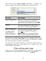
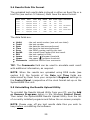
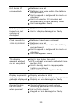
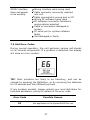
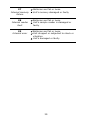
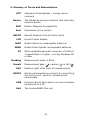
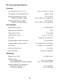
1
This Manual Copyright © 2007 by Hygiena LLC All rights reserved. No part of this manual may be reproduced, stored in a retrieval system, or transmitted, by any means or in any form, without the prior permission of Hygiena LLC. The information contained in this manual is subject to change without notice. Hygiena LLC assumes no responsibility for any errors that may appear in this document. Document number: Document revision: M980099 Issue 2, November 2009 Copyrights and Trademarks Worldwide Patents Pending. Hygiena, SystemSURE Plus, systemSURE II, Ultrasnap, SureTrend and dataSURE II are trademarks of Hygiena LLC. I Operating Precautions and Limitations of Use IMPORTANT: Hygiena’s products are designed and constructed to be safe and without risk to health when properly used in accordance with the supplied documentation and when the operating precautions outlined in this manual are fully observed. IMPORTANT IT IS ESSENTIAL THAT THE USER OF THIS MANUAL IS AWARE OF THE POTENTIAL HAZARDS ASSOCIATED WITH THE UNIT AND ITS ACCESSORIES. ALL OPERATORS SHOULD BE FAMILIAR WITH THE SAFETY PRECAUTIONS AND WARNINGS GIVEN IN THIS SECTION BEFORE ATTEMPTING TO OPERATE THE UNIT. IF THE UNIT IS USED IN A MANNER WHICH IS NOT SPECIFIED BY THE MANUFACTURER, THE PROTECTION PROVIDED BY THE EQUIPMENT MAY BE IMPAIRED. The following symbol is used in this manual: Description: CAUTION / WARNING The precautions to be observed relate to the transportation and use of all types of solid state electrical/electronic instrumentation and to the handling of the Ultrasnap devices. These precautions are outlined below. II Operating Environment and Electrostatic Precautions WARNING: Do not use the unit in any area which has been, or is thought to have been, exposed to explosive or flammable gases or vapours. CAUTION: Avoid operating the unit in direct sunlight, as this may affect its performance. Never leave the unit in direct sunlight, even when turned off. CAUTION: Do not expose or operator the unit in extremes of temperature (see section 10), and minimise any exposure to electrostatic charges. Unit Handling and Use CAUTION: Care should be taken not to drop the unit or subject it to any form of rough physical handling, both during normal use and during storage and transportation. CAUTION: To avoid the risk of injury or choking, never use the unit neck strap in situations where it could get caught in machinery, etc. Batteries WARNING: Use only non-rechargeable alkaline batteries, or rechargeable NiMH or NiCD batteries, of types specified in section 10. WARNING: Do not use batteries with individual cell voltages greater than 1.65V, as this will cause permanent damage to the unit. CAUTION: All batteries should be disposed of in accordance with your local regulations. III Use and Insertion of Ultrasnap Devices CAUTION: Refer to the Ultrasnap data sheet and kit insert for details before using the device, and observe all federal, state and local environmental regulations. CAUTION: Do not force Ultrasnap devices into the unit. Do not attempt to insert any object other than an approved Ultrasnap device into the unit. CAUTION: Ensure that the Ultrasnap device is clean and dry before inserting it into the unit. Keypad Buttons CAUTION: Do not use excessive force when pressing any of the buttons on the unit's keypad. RS232 Connector WARNING: Computer equipment connected to the RS232 connector at the top of the unit must conform to BS EN 60950/IEC950 standards. Unit Casework and Serviceability WARNING: There are no Operator serviceable parts inside the unit. Removal or opening of the unit's casework will void the warrantee. IV WEEE Directive Compliance The SystemSURE Plus unit should be disposed of in accordance with the European Union WEEE Directive 2002/96/EC, on Waste Electrical and Electronic Equipment. WARNING: Do not dispose of this product into unsorted municipal waste or a public landfill. Please contact your local distributor for details of how to correctly dispose of this product. Regulatory Limitations of Use The SystemSURE Plus unit has been designed to meet the following general, safety and EMC requirements: General Safety Low Voltage Directive 73/23/EEC EMC Directive 89/336/EEC BS EN 61010-1:2001, IEC 61010-1:2001 UL 61010B-1 CAN/CSA C22.2 1010.1-92 EMC EN 55022:1998 – Class B FCC CFR47 Pt15.109 – Class B EN 61000-4-3:1996 ESD EN 61000-4-2:1995 + A1 The SystemSURE Plus unit is manufactured under ISO 9001 controls. V Declaration of Conformity The SystemSURE Plus unit has been designed in accordance with, and satisfies the requirements of, article 11 of the Low Voltage Directive 73/23/EEC as realigned by 93/68/EEC on the harmonisation of the laws of the Member States relating to electrical equipment designed for use within certain voltage limits, to the essential requirements of BS EN 61010-1:2001. The SystemSURE Plus unit has been type tested by EMC Projects Limited (a UKAS and CAA approved test facility and UK appointed Notified Body), and issued with a Certificate of Compliance No. 6349/07 to the following EMC standard: EN61326 : 1997 Covering: Radiated Emissions Radiated Emissions Radiated Immunity Electrostatic Discharge (EN 55022:1998 – Class B) (FCC CFR47 Pt15.109 – Class B) (EN 61000-4-3:1996) (EN 61000-4-2:1995 + A1) Satisfying the EMC Directive(s) 89/336/EEC and 92/31/EEC as realigned by 93/69/EEC. VI TABLE OF CONTENTS 1. Introduction .......................................................... 1 1.1 Key Unit Features .............................................. 1 1.2 Accessories and Consumables .............................. 1 1.3 Principle of Operation ......................................... 2 2. Basic Unit Operation ............................................. 3 2.1 Unit Description ................................................. 3 2.2 Keypad Symbols ................................................ 5 2.3 Display Layout and Icons .................................... 5 2.4 Fitting the Batteries ............................................ 6 2.5 Turning the Unit On ............................................ 8 2.6 Low Battery Indicator ......................................... 8 2.7 Internal Calibration Self-Checks ........................... 9 2.8 Turning the Unit Off.......................................... 10 2.9 Power Saving Standby Mode .............................. 10 2.10 Low Memory Warning ..................................... 10 3. Sample Measurements and Test Results ............. 11 3.1 3.2 3.3 3.4 Programmable Test Locations ............................ 12 Using Test Plans .............................................. 13 Taking a Sample Measurement........................... 14 Performing a Retest .......................................... 16 4. Set-up Menu Options ........................................... 17 4.1 4.2 4.3 4.4 4.5 4.6 4.7 4.8 Selecting a User ID .......................................... 18 Selecting a Test Plan ........................................ 18 Defining Program Limits .................................... 19 Viewing Stored Test Results ............................... 20 Erasing the Test Results Memory ........................ 20 Viewing Statistics Data and Test Failures ............. 21 Setting the Clock Time and Date ........................ 22 Adjusting the LCD Contrast................................ 22 5. Uploading Test Results to a PC ............................ 24 5.1 5.2 5.3 5.4 5.5 Conditions of Use ............................................. 24 Installing the Results Upload Utility..................... 24 Using the Results Upload Utility .......................... 25 Results Data File Format ................................... 29 Uninstalling the Results Upload Utility ................. 29 VII 6. Operator Maintenance......................................... 30 6.1 Cleaning the Casework ..................................... 30 6.2 Replacing the Batteries ..................................... 30 6.3 Cleaning and Replacing the Protective Pocket ....... 30 7. Troubleshooting .................................................. 33 7.1 Unit Beeps ...................................................... 33 7.2 Troubleshooting Tips ........................................ 34 7.3 Unit Error Codes .............................................. 37 8. Unit Warranty and Returns ................................. 40 8.1 Warranty Duration ........................................... 40 8.2 Particular Exclusion .......................................... 40 9. Glossary of Terms and Abbreviations .................. 41 10. Technical Specification...................................... 42 11. Appendix........................................................... 43 VIII 1. Introduction The SystemSURE Plus is intended to help the operator demonstrate due diligence and compliance with HACCP and other Hygiene regulations by allowing simple hygiene monitoring via the use of an ATP bioluminescent test. The SystemSURE Plus system consists of two elements: the disposable Ultrasnap device and the handheld reader unit. This Operator’s Manual provides a detailed description of how to use the SystemSURE Plus unit, and how to handle maintenance and troubleshooting. For full details on the Ultrasnap device, please refer to the Ultrasnap data sheet and kit insert. For any additional technical assistance, please contact your local distributor. 1.1 Key Unit Features The main features of the SystemSURE Plus unit are: Small and lightweight reader Large clear liquid crystal display Highly sensitive luminometer Short measurement time – just 15 seconds Internal calibration self-check light source 251 user programmable result thresholds Large 2000 test result memory 20 test plans of up to 251 locations each 50 User IDs RS232 interface for results uploading to a PC Uses two standard or rechargeable batteries Replaceable protective sample pocket 1.2 Accessories and Consumables Please contact your local distributor for details of unit accessories and consumables. 1 1.3 Principle of Operation The Ultrasnap device uses a bioluminescent chemistry technology to convert an invisible concentration of ATP present in the sample into a visible light output. This extremely low-level light output is measured by the SystemSURE Plus unit to produce both a quantitative and qualitative result. + + The quantitative result is a number in the range 0 to 9999, expressed in terms of Relative Light Units (RLUs). Although RLUs are not a recognised international unit of light measurement (such as lux), they do provide a real measure of the amount of light output by the ATP bioluminescent test. In this application, 1 RLU is roughly equivalent to 1 fmol of ATP. The quantitative RLU reading is then compared against user programmable thresholds to provide an overall qualitative pass ( ), caution ( ) or fail ( ) result. PLEASE NOTE The SystemSURE Plus unit is a highly sensitive and delicate measurement device. To avoid damage and degradation in performance, the unit should be treated with the utmost care and respect at all times. 2 2. Basic Unit Operation IMPORTANT Please ensure that you have read and understood all of the “Operating Precautions and Limitations of Use” at the beginning of this manual before continuing any further. 2.1 Unit Description The unit has the following front and rear external features: Unit lid Liquid crystal display Keypad 3 Neck strap anchor Serial number label Battery compartment Opening the lid reveals the following internal features: RS232 connector cover Protective pocket and sample insertion port For details on the RS232 connector and protective pocket, refer to sections 5 and 6.3 respectively. 4 2.2 Keypad Symbols The keypad is arranged with the following buttons: Power on/off button Menu select button Up/increase button Start/accept button Down/decrease button Program select button Statistics shortcut button The functions of these buttons are explained in detail in the following sections of this manual. or button will make it TIP: Pressing and holding down the auto-repeat. The longer you hold it down, the faster it goes. 2.3 Display Layout and Icons The liquid crystal display (LCD) has the following layout: 5 The upper half of the display contains the status icons and the large RLU result digits: Low battery warning icon Lid icon - flashes when the lid needs to be closed Insert icon – arrow flashes when the Ultrasnap device should be inserted Remove icon – arrow flashes when an Ultrasnap device needs to be removed Pass result icon Caution result icon Fail result icon Sample measurement reading in Relative Light Units (RLUs) Retested icon – identifies the failed test result as having been retested Retest result icon – identifies the Program location or test result as a retest result 2.4 Fitting the Batteries The unit is designed to operate from both non-rechargeable alkaline batteries and rechargeable Nickel Metal Hydride (NiMH) or Nickel Cadmium (NiCD) batteries: Battery Technology Nominal Cell Voltage Relative Capacity Alkaline NiMH NiCD 1.5V 1.2V 1.2V 1.0 0.6 0.5 The unit requires two batteries of size AA, LR6 or E91. 6 TIP: For best results, always use a quality brand of Alkaline battery and replace them as soon as they become flat (see section 2.6). WARNING: Do not mix batteries of different technologies, or use recharged alkaline batteries as these are prone to overcharging and leaking, which may cause permanent unit damage and malfunction. The batteries are fitted by unclipping the battery cover on the back of the unit, and inserting both batteries with their positive terminals () pointing towards the top of the unit: (1) Remove cover (2) Insert batteries (3) Replace cover CAUTION: Take care not to insert the batteries the wrong way round, as this may cause permanent damage to the unit’s internal electronics. When the batteries are inserted correctly, the unit will automatically turn on and enter the clock set-up mode. Refer to section 4.7 for how to set the time and date. 7 2.5 Turning the Unit On To turn the unit on, press the button. The unit will beep once and display the power-up self-check screen: NOTE: If the batteries are too flat, the unit may turn on and back off again automatically, or may not turn on at all. If this happens, replace the batteries immediately. The unit will then perform its internal calibration self-checks (see section 2.7 below). NOTE: If the clock is not set, the unit will automatically enter the time and date set-up mode (see section 4.7) before performing its calibration self-check. 2.6 Low Battery Indicator The low battery icon indicates the state of the batteries: Icon Battery State Not visible Good Visible Low – replace batteries soon Flashing Flat – replace batteries now! When the batteries are completely flat, the unit will flash the icon, beep three times, and automatically turn off: CAUTION: Never leave flat batteries in the unit, as they are prone to leaking/corrosion, which will damage the unit. 8 TIP: Always store the unit in a cool dry place when not in use, as elevated temperatures will shorten the battery life. 2.7 Internal Calibration Self-Checks When the unit is turned on (see section 2.5), it performs a series of internal calibration self-checks, as the display counts down from 60 to 0 seconds: NOTE: During the self-check sequence, there must not be an Ultrasnap device in the unit and the lid must remain closed. If icon is shown with the arrow flashing, open the lid and the remove the Ultrasnap device from the unit. If the icon is flashing, close the lid. button can be pressed at any time to access the setTIP: The up menu options. Refer to section 4 for further details. When the calibration self-checks are complete, the unit is ready to perform a sample measurement: Please refer to section 3 for details of how to perform a sample measurement. 9 NOTE: When the unit is ready to perform a measurement, with the lid closed and no Ultrasnap device present, the unit will automatically perform a zeroing cycle under any the following circumstances: The unit is turned on for a prolonged period of time (typically 30 minutes). The unit is used in an environment where the temperature changes significantly (typically 5oC). The user presses and holds down the button for 1 second. 2.8 Turning the Unit Off button. The unit will beep once To turn the unit off, press the and the display will go blank. NOTE: To avoid accidental turn off, the button is disabled whilst the unit is performing a sample measurement. 2.9 Power Saving Standby Mode If the unit is on but has not been used for 10 minutes, it will automatically enter a power saving standby mode and the display will go blank. To exit standby mode and turn the unit back on, simply press the button, as per section 2.5. 2.10 Low Memory Warning The unit can store up to 2000 test results in its internal memory. When the memory is more than 95% full (i.e. less than 100 tests remaining) the following warning symbol is displayed: When the memory becomes completely full, no more tests can be performed until the memory is either erased or uploaded to the PC. Refer to sections 4.5 and 5 respectively. 10 3. Sample Measurements and Test Results With the unit turned on, and having completed its internal calibration self-checks, it is then ready to perform a new sample measurement, and the display shows the following details: Insert sample icon Ready for new test Test Plan and step Upper threshold Program location Lower threshold User ID Various keypad options are now available, as detailed in each of the following sections: Button User ID Test Plan Action Section Access set-up menu options 4 Select different User ID 4.1 Select different Test Plan 4.2 Select program number 1 Second +Sample 3.1 / 3.2 Perform zeroing cycle 2.7 Start new measurement 3.3 View previous test results 4.4 Show statistical result data 4.6 Turn unit off 2.8 11 3.1 Programmable Test Locations The unit can store up to 251 individual programmable test locations (numbered PROG# 0 to PROG# 250). Each location is assigned a pair of upper () and lower () result threshold values, plus an optional location name. When a sample measurement result is displayed, the RLU reading is compared against the selected Program thresholds to determine the overall Pass, Caution or Fail result: RLU Banding Result Reading < lower threshold () Pass Reading > lower threshold () but < upper threshold () Caution Reading > upper threshold () Fail For details of how to determine the appropriate program thresholds for your particular operating procedures, please contact your local distributor. To set-up the Program thresholds, refer the section 4.3. button, then use the To select a Program location press the buttons to change the Program PROG# to the desired and Program location, followed by the button to accept the new location, or the button to cancel the selection. TIP: Whilst selecting a PROG#, the display also shows the time and date that the Program location was last tested. 12 NOTE: If the selected Program location does not have any thresholds defined, they must be set-up using the PROGRAM menu option (see section 4.3) before the Program can be used. 3.2 Using Test Plans The unit can also store up to 20 individual Test Plans (numbered PLAN# 1 to 20), each consisting of a list of up to 251 Program locations, specified in the order in which each location should be tested. An example set of Test Plans for a typical week might be: PLAN# 1 Monday PLAN# 2 Tuesday PLAN# 3 Wednesday PLAN# 4 Thursday PLAN# 5 Friday PROG#1 PROG#1 PROG#2 PROG#3 PROG#4 PROG#2 PROG#7 PROG#8 PROG#9 PROG#5 PROG#3 PROG#6 PROG#5 PROG#4 PROG#6 PROG#7 PROG#10 PROG#9 PROG#8 PROG#8 PROG#9 PROG#7 PROG#6 PROG#3 PROG#5 PROG#2 PROG#4 PROG#1 PROG#10 Test Plans are defined by using the SureTrend Windows software. Please refer to the separate SureTrend User’s Manual for full details. To select a Test Plan, use the TEST PLAN menu option, as described in section 4.2. NOTE: If Test Plan PLAN#0 is selected, or no Test Plans have been defined, any of the 251 Program locations can be selected, as detailed in section 3.1. button and To select a location within the Test Plan, press the use the and buttons to change the PLAN# and associated Program location PROG#, followed by the button to accept the new location, or the button to cancel the selection. 13 TIP: Whilst selecting a PROG#, the display also shows the time and date that the Program location was last tested. NOTE: If the selected Test Plan Program location does not have any thresholds defined, they must be set-up (see section 4.3) before the location can be tested. 3.3 Taking a Sample Measurement IMPORTANT: Please refer to the Ultrasnap data sheet and Kit Insert for full details of how to use the Ultrasnap device. NOTE: Always allow the unit sufficient time to acclimatise to any change in environment, temperature or humidity before taking sample measurements. To perform a sample measurement, follow the steps below: Swab the sample area and activate the Ultrasnap device (see Kit Insert for details) Open the unit lid, insert the Ultrasnap device into the unit, and close the lid Press the button and wait 15 seconds for the result to be displayed WARNING: Always ensure that the exterior of the Ultrasnap device is clean and dry before inserting it into the unit. Never insert anything other than an Ultrasnap device into the unit. Never insert a device into the unit when the protective pocket is removed (refer to section 6.3). 14 Whilst the measurement is being performed, the display counts down from 15 to 0: NOTE: For consistent results, always keep the unit upright and steady whilst it is performing a measurement to ensure that the liquid in the Ultrasnap device is at the bottom of the tube. When the measurement is complete, the RLU test result and overall pass/caution/fail result are displayed: Pass / Caution / Fail RLU result Test number Upper threshold Program location Lower threshold Test time Test date TIP: A failed test result ( ) can be selected for retesting by pressing the button, followed by the button to select the Program location. See section 3.4 for details. Now remove the Ultrasnap device and dispose of it. NOTE: For best results, and to prevent dust and dirt ingress, always keep the unit lid closed when not inserting or removing an Ultrasnap device. Previous test results can be viewed by pressing the and buttons (see section 4.4), or the results statistical data can be obtained by pressing the button (see section 4.6). 15 TIP: The unit can be re-zeroed by removing the Ultrasnap device, closing the lid and then pressing and holding down the button for 1 second. The unit will then perform a 15-second zero measurement. 3.4 Performing a Retest When viewing a failed ( ) test result (see sections 4.4 and 4.6), the program location can be selected for retesting by pressing the button, followed by the button: NOTE: It is only possible to select a program location for retest if the most recent test result for that location was a failure ( ). icon next to the Having selected retest mode (signified by the PROG#), perform the sample measurement in the usual way, using a new Ultrasnap device, as described in section 3.3. Once the retest measurement is complete, the original failed test icon, and the new test result is result is marked with the tagged with the icon: NOTE: Retest mode is automatically deselected once the new measurement is complete, or can be manually cancelled by pressing the button and selecting a new program location (see sections 3.1 and 3.2). 16 4. Set-up Menu Options With the unit turned on, the Set-up Menu can be accessed by pressing the button. The following seven menu options are then available: Select User ID Select Test Plan Define Program limits View stored test results View statistical data Set clock time and date Adjust LCD contrast Use the and buttons to scroll through the menu list, and then press the button to select the required menu option, or the button the exit the menu. 17 4.1 Selecting a User ID The unit can store a list of up to 50 User IDs, allowing each test result can be tagged with the ID of the individual test operator. PLEASE NOTE: The User ID list can only be defined by using the SureTrend Windows software. For further details, please refer to the separate SureTrend User's Manual. Having selected the USER ID menu option (see section 4), use the and buttons to scroll through the list of User IDs, then press the button to select the new User ID, or the button to cancel the selection. TIP: USER#0 is the default selection if no User ID list has been defined. This allows Any User to operator the unit. 4.2 Selecting a Test Plan The unit can be loaded with up to 20 different Test Plans, (numbered PLAN# 1 to 20) each consisting of between 1 and 251 test locations, specified in the order in which they would normally be tested. PLEASE NOTE: Test Plans can only be defined by using the SureTrend Windows software. Please refer to the separate SureTrend User's Manual for further details. Having selected the TEST PLAN menu option (see section 4), and buttons to scroll through the list of Test Plans, use the and then press the button to select the new Plan, or the button to cancel the selection. TIP: PLAN#0 allows any of the 251 test locations to be tested in any order, and is the default selection if no Test Plans have been defined or selected. Please refer to section 3.2 for details of how to select each Program location within a selected Test Plan. 18 4.3 Defining Program Limits The unit has the ability to store a list of up to 251 Program test points (numbered PROG# 0 to 250), each with its own upper () and lower () result threshold values and location name. The Program result thresholds can either be set-up on the unit (see below), or downloaded using the SureTrend or dataSURE II Windows software. PLEASE NOTE: The associated location names can only be defined by using the SureTrend software. Please refer to the separate SureTrend User's Manuals for further details. For details of how to use the Program settings, please refer to section 3.1. TIP: PROG#0 has a special function, whereby the threshold values defined for PROG#0 are used as the initially values when setting-up the other PROG# thresholds. Thus setting PROG#0 with your typical threshold values will save time when setting-up the other Programs. To set the Program result thresholds on the unit, first select the PROGRAM menu option (see section 4), then use the and buttons to scroll through the list of Programs, followed by the button to select the Program to be changed: PROG# Next use the and buttons to first change the value of the upper threshold (), followed by the button; and then to change the value of the lower threshold (), followed by the button to store the new values: upper threshold () lower threshold () 19 TIP: Pressing the button at any point will exit this set-up mode, leaving both the PROG# and thresholds unchanged. 4.4 Viewing Stored Test Results The unit can indefinitely store a maximum of 2000 test results in its internal memory, even when the batteries are flat or removed. To view these stored test results, select the MEMORY menu option (see section 4), then use the and buttons to scroll through the test results, pressing the button to exit: TIP: Whilst reviewing the stored test results, a failed ( ) Program location can be selected for retesting by pressing the button. Refer to section 3.4 for details. 4.5 Erasing the Test Results Memory The entire test results memory can be cleared using the MEMORY ERASE function, by first selecting the MEMORY menu option (see section 4.4) and then pressing and holding down the button for 2 seconds. The display will then show the total number of stored results to be erased: 20 To accept and start the erase function, press and hold down the button for 1 second, or press any other button to exit the option. WARNING Once the test results have been erased from memory they are permanently deleted and can no longer be viewed or uploaded to a PC. NOTE: Once started, the erase function can not be stopped, and will take about 30 seconds to erase a full 2000 results. 4.6 Viewing Statistics Data and Test Failures The test results database can be analysed by selecting the STATISTICS menu option (see section 4) to display a simple comparison of all the stores results: TIP: The function. button also provides a direct shortcut to this and buttons can then be used to scroll through all of The the failed ( ) test results, pressing the button to exit: 21 TIP: Whilst reviewing the failed test results, a Program location can be selected for retesting by pressing the button. Refer to section 3.4 for details. 4.7 Setting the Clock Time and Date To set or change the clock time, date, and format, select the CLOCK menu option (see section 4). Then use the and buttons change each time and date value, followed by the button to accept each new value in turn. First the time is set (style hours minutes), which can be configured as either a 12-hour clock (select AM or PM) or a 24hour clock (select 24H): AM, PM or 24H hours minutes Next the date is set (format date/month month/date year), which can be configured for either European format (select D/M/Y for date, month, year) or American format (select M/D/Y for month, date, year): D/M/Y or M/D/Y date (D/M/Y) or month (M/D/Y) month (D/M/Y) or date (M/D/Y) year TIP: Pressing the button at any point will exit the clock set-up mode, leaving the time and date unchanged. NOTE: The clock does not have automatic daylight saving adjustment. If this is required, the time must be manually changed when necessary. 4.8 Adjusting the LCD Contrast The contrast of the LCD screen is factory set at its optimum level for normal operating conditions. However, in extremes of temperature the display may appear too dark or light. 22 This setting can be manually adjusted by selecting the LCD CONTRAST menu option (see section 4) and using the or button to increase or decrease the contrast level, followed by the button to store the new setting: darker (+1 to +5) normal lighter 23 (0) (-1 to -5) 5. Uploading Test Results to a PC The test results stored in the unit's memory can be uploaded to a PC using the SystemSURE Results Upload Utility. This utility is supplied on the CD-ROM with the unit. NOTE: Although the screen shots in this section relate to Windows XP, the software can also be used on other versions of Microsoft Windows, such as Windows 98 and 2000. 5.1 Conditions of Use As Hygiena LLC has no control over the specification, state or use of any computer equipment on which this software is installed or used, the following Conditions of Use apply: IMPORTANT The software is provided “as is” without warranties of any kind either expressed or implied including warranties of merchantability or fitness for a particular purpose. Hygiena shall not be liable for any loss of profit, loss of use, loss of software, loss of data, interruption to business, nor for indirect, special, incidental or consequential damages of any kind whether under this agreement or not. 5.2 Installing the Results Upload Utility IMPORTANT: By installing this software, you are deemed to be in acceptance of the Conditions of Use specified in section 5.1 above. Do not install this software if you are not in agreement with these conditions. NOTE: If you already have a previous version of the Results Upload Utility installed on your PC, it is highly recommended that you uninstall it before installing the new version. See section 5.5 for details. 24 The software is installed onto your computer by inserting the CD into your CD-ROM drive and following the installation script screen prompts. If the install script does not automatically start, open the CD-ROM folder from the My Computer icon on the PC desktop and run the Install application. Once installed, the new software is run by clicking on the SystemSURE Results Upload Utility shortcut from the Windows start menu: TIP: This software can be used with both the SystemSURE Plus and systemSURE II units. 5.3 Using the Results Upload Utility Running the upload utility from the Windows start button brings up the following software dialogue box: 25 Now connect the serial interface cable (as supplied with the unit) between the SystemSURE Plus unit and one of the RS232 or USB ports on your PC: PC (1) Fold back rubber cover to access RS232 socket (2) Insert small RJ10 (3) Connect other plug into unit’s end of cable to RS232 socket PC’s COM port NOTE: Select the appropriate RS232 or USB cable most suitable for your PC. A USB-to-RS232 adapter or USB Smart cable can also be used. See section 11; Appendix on page 43 for instructions for the installation and connection of SystemSURE USB Smart Cable. Please contact your local distributor for further details. Next select the correct Serial port from the available list: 26 Then select the file save as type, depending on whether you want to create a Microsoft Excel data file or a plain text file: File Type Advantages Excel workbook file Generates a Microsoft Excel compatible file, which is more secure than a text file as the results data cannot be modified. This does not require Excel to be installed on the same PC. Text file Generates a simple text file, which should work on any PC. However, the data in the file is less secure and can be easily modified. Excel file using DDE Generates a secure Microsoft Excel file using Dynamic Data Exchange (DDE). However, Excel must be installed on the same PC. This option provides compatibility with earlier versions of the Results Upload Utility WARNING: Do not interact with Excel whilst the data is being uploaded using DDE mode, as it may corrupt the data file format. Next specify a suitable File name for the uploaded results to be stored in. This file name must be unique, as previously created file names cannot be reused or overwritten. You also have the option whether you wish the upload utility to automatically open the saved data file for viewing once the results upload is complete: Finally, turn on the SystemSURE Plus unit using the button, and begin the upload process by clicking the button. 27 The software then attempts to establish communications with the unit and, if successful, the unit display shows: The results are then uploaded from the unit and stored in the specified data file on your PC's hard disk. This will take between 2 to 3 minutes to upload a full 2000 results. Once the results have been uploaded and stored, you are given the option to erase all of the test results from the SystemSURE Plus unit. WARNING: Please ensure that you can open and view the test results in the data file before clicking the button to erase them from the SystemSURE Plus unit. Once erased from the unit, the results data cannot be re-uploaded to the PC. If you choose not to erase the results from the SystemSURE Plus unit, they can be manually erased later by using the MEMORY ERASE function (see section 4.5). When the upload is complete, turn off the unit and disconnect the serial cable from the SystemSURE Plus unit – ensuring that the black rubber RS232 cover is pushed back down and that the lid can be fully closed: Push RS232 cover back under lip 28 5.4 Results Data File Format The uploaded test results data is stored in either an Excel file or a text file (see section 5.3 above). Both have the same format: Unit# Test# Date Time Prog Result RLU Lower Upper Comments Pass 26 100 200 1721 1 12/05/03 08:04 0 1721 2 12/05/03 08:05 0 Pass 35 100 200 1721 3 12/05/03 08:08 1 Caution 172 150 400 Re-cleaned 1721 4 12/05/03 08:17 1 Pass 73 150 400 Retest 1721 5 12/05/03 17:42 0 Fail 257 100 200 End of shift 1721 6 12/05/03 17:44 1 Pass 141 150 400 The data fields are: Unit# Test# Date Time Prog Result RLU Lower Upper Comments - the unit serial number (see unit rear label) the test number the date the test was performed the time the test was performed the PROG number used for the test the overall Pass/Caution/Fail test result the test reading in RLUs the lower () program threshold the upper () program threshold additional field for user comments TIP: The Comments field can be used to annotate each result with additional information, as required. NOTE: When the results are uploaded using DDE mode (see section 5.3) the formats of the Date and Time fields are determined by Excel from your computer’s Regional settings in the Control Panel, irrespective of the clock format set-up on the SystemSURE Plus unit. 5.5 Uninstalling the Results Upload Utility To uninstall the Results Upload Utility from your PC, use the Add or Remove Programs option in the Windows Control Panel. Then select the SystemSURE Results Upload Utility from the list of currently installed programs and follow the on-screen prompts. NOTE: Please copy off any test results data files you wish to keep before uninstalling the software. 29 6. Operator Maintenance The SystemSURE Plus unit does not require any specific routine operator or service engineer maintenance. 6.1 Cleaning the Casework Clean the unit casework when required using a dry or slightly damp cloth only. WARNING: Never clean the unit using a wet cloth, or by washing it under running water. CAUTION: Do not use solvents or other strong cleaning solutions as these may attack and deform the unit’s plastic components, and seriously degrade its performance. 6.2 Replacing the Batteries For best results, the batteries should replaced when the low battery warning icon is flashing. Refer to section 2.4 for how to fit new batteries – taking care not to mix the old batteries with the new ones. IMPORTANT: Always dispose of old batteries in accordance with your local authority regulations. 6.3 Cleaning and Replacing the Protective Pocket The unit is designed with a special protective pocket, which can be removed for cleaning or replacement if required. WARNING: Always turn off the unit before removing the protective pocket. 30 To remove the protective pocket, open the unit’s lid, tightly grasp the finger grip of the pocket, gently pull the pocket upwards, and remove it from the unit. (1) Grasp finger grip (2) Pull pocket upwards (3) Remove pocket CAUTION: Great care should be taken when removing the pocket not to damage it or the surrounding casework. Do not use excessive force. Never use a tool to prise out the pocket. Carefully clean the interior of the pocket using water or a very mild detergent solution, ensuring that the pocket is completely dry and clean before putting it back into the unit. Continued on the next page 31 WARNING: Do not use solvents or other strong chemicals as these will degrade the clear optical section of the pocket and affect the performance of the unit. To replace the pocket, carefully insert it into the unit, ensuring that it is correctly orientated, and then push it fully down until it clicks into position: (1) Insert pocket in the orientation shown (2) Push fully down until it clicks into place (3) Push RS232 cover back under lip WARNING: Do not use excessive force when replacing the pocket. If the pocket jams during insertion, remove it fully, check for obstructions or damage, and then try again. Finally ensure that the black rubber RS232 cover is pushed down and that the lid can be fully closed – see section 5.3. 32 7. Troubleshooting This section lists typical problems that might be encountered when using the unit, and their possible causes and remedies. Some problems can be rectified by the operator, whilst others may require technical assistant: Severity Action Required This indicates a cause which can be rectified by the operator. This indicates a cause which may require technical attention for rectification. Contact your local distributor for further assistance. 7.1 Unit Beeps During normal use, the unit emits a variety of different beeping sounds: Beep Type Possible Causes Short highpitched tone Long high-pitched tone Unit calibration self-checks complete Sample measurement complete Results memory erase complete Long low-pitched tone Invalid date entered Program thresholds not set-up Invalid program threshold limits entered Attempting to select a non-failed (pass/caution) result for retesting Unit turned on or off Sample measurement started Communications established with PC Results memory being erased 33 Two short highpitched tones Calibration self-checks required – remove Ultrasnap device and close the lid Three short highpitched tones Clock set-up required Batteries are flat Memory full warning Memory erase requested Unit error (see section 7.3 below) 7.2 Troubleshooting Tips If the unit appears to be malfunctioning for any reason, carry out a thorough check for any obvious damage to the case, lid, LCD screen, battery contacts, etc, caused by dropping or excessive physical mishandling. The following table lists typical symptoms and their possible causes. Symptom Possible Causes Unit will not turn on when the button is pressed Unit will not turn off when the button is pressed Unit is busy performing a reading or calibration self-check operation Unit lockup – remove the batteries for 30 seconds, then insert them again Unit or keypad damaged or faulty Batteries are flat Batteries are the wrong type Batteries incorrectly inserted Unit or keypad damaged or faulty 34 Unit turns off unexpectedly Batteries are flat Batteries are loose within the battery compartment Unit dropped or subjected to shock or vibration Unit not used for 10 minutes and automatically enters standby mode Unit damaged or faulty Unit beeps when turned on, but nothing is displayed Batteries are flat Unit or display damaged or faulty Clock reverts to Batteries have been replaced Batteries are flat Batteries are loose within the battery compartment Unit dropped or subjected to shock or vibration Unit damaged or faulty 12:00 01/01/2000 The display appears washed out or very dark Unit is too hot or too cold LCD contrast incorrectly adjusted (see section 4.8) Unit is being used in inappropriate lighting conditions Unit or display damaged or faulty Display segments Display window is dirty missing or Display window is scratched or dented garbage displayed Display or unit damaged or faulty Keypad button has no effect when pressed Some buttons only work when selecting particular unit functions Lid not fully closed Keypad or unit damaged or faulty 35 Unit lid will not close properly or springs open during use Protective pocket incorrectly or not fully inserted RS232 connector cover is interfering with the lid (see section 6.3) Ultrasnap device incorrectly or not fully inserted Lid or unit casework damaged Measurement result is always zero RLU or is much lower expected Incorrect use of Ultrasnap device Unit not in upright position when measurement taken Ultrasnap device is out-of-date Unit being used in an unstable thermal environment – turn the unit off and back on again Protective pocket or Ultrasnap device not fully inserted into unit Protective pocket dirty or severely scratched Protective pocket damaged Unit damaged or faulty Measurement result is higher than expected Incorrect or inconsistent use of the Ultrasnap device Lid not fully closed Unit being used in an unstable thermal environment – turn the unit off and back on again Unit casework or lid damaged or faulty 36 RS232 interface does not appear to be working Wrong interface cable being used Cable connector incorrectly inserted into unit Cable connected to wrong port on PC Wrong PC software being used PC software incorrectly installed or wrong options selected Cable or connectors damaged or broken PC serial port or system software faulty Unit damaged or faulty 7.3 Unit Error Codes During normal operation, the unit performs various self-checks on its internal components. If a problem is detected, the display will show an error number: TIP: Most problems are likely to be transitory, and can be cleared by pressing the button, or by removing the batteries for 30 seconds and then reinserting them. If any problem persists, please contact your local distributor for technical assistance, giving full details of the error code. Error Code Possible Causes E1 Not applicable on the SystemSURE Plus unit 37 E2 The unit is being used outside of the Temperature out specified operating temperature range of range (see section 10) The unit has been stored in an environment which is outside of its specified operating temperature range – allow unit to acclimatise before use Unit damaged or faulty E3 Erratic measurement Unit environment unstable or used in an area of high electromagnetic noise Unit tilted whilst measurement being performed Unit lid damaged and allowing light in Protective pocket dirty or severely scratched Unit damaged or faulty E4 User settings undefined The user configurable settings are undefined - check and re-set the CLOCK format, USER#, PLAN# and PROG# data E5 Program, Test Plan or User ID undefined Program thresholds not defined, and have been reset to the default values (10 and 30) Test Plan data not defined User ID not defined E6 Calibration selfchecks failed Unit operating environment unstable Protective pocket dirty or severely scratched Lid not fully closed Lid seal damaged Protective pocket damaged Unit damaged or fault 38 E7 Batteries are flat or loose Internal memory Unit’s memory damaged or faulty failure E8 Internal reader fault E9 Internal error Batteries are flat or loose Unit’s sample reader is damaged or faulty Batteries are flat or loose Unit dropped or subjected to shock or vibration Unit’s damaged or faulty 39 8. Unit Warranty and Returns The Supplier warrants the SystemSURE Plus unit, when purchased new, to be free from defects in materials and workmanship, and will repair or replace, at their discretion, any SystemSURE Plus unit which, used under proper conditions, exhibits such defects. Under the terms of this warranty, the product must be returned in the original packaging, transportation prepaid, with a copy of the Proof of Purchase, to your local distributor. Contact your local distributor to receive authorisation to return the instrument, and enclose a detailed description of the problem. 8.1 Warranty Duration This warranty is provided to the original purchaser for one year from the date of purchase. In no event will Hygiena be liable for indirect, incidental or consequential damages; the original user’s remedies being limited to repair or replacement of the unit at the manufacturer’s option. 8.2 Particular Exclusion Unauthorised modification of any part of the SystemSURE Plus unit or the use or attachment of any peripheral not supplied or specified by Hygiena will void this Warranty. WARNING: Use only the accessories and consumables supplied by Hygiena. The use of any non Hygiena supplied accessories and consumables will invalidate the warranty. 40 9. Glossary of Terms and Abbreviations ATP Device Adenosine Triphosphate – energy carrier molecule The Ultrasnap sample collection and chemistry reaction device EMC Electro-Magnetic Compatibility fmol Femtomole (10-15 moles) HACCP LCD Hazard Analysis Critical Control Point Liquid Crystal Display NiCD Nickel Cadmium rechargeable batteries NiMH Nickel Metal Hydride rechargeable batteries PC Reading Result RLU IBM compatible personal computer of Pentium 1 specification or higher, running Windows 98 or later Measurement value in RLUs Measurement pass ( ), caution ( ) or fail ( ) Relative Light Units (unit of measurement) RS232 Serial communications protocol for connecting the unit to a PC, used for uploading test results data USB Universal Serial Bus used to connect computer peripherals to a PC Unit The SystemSURE Plus unit 41 10. Technical Specification General Unit dimensions (W x H x D) 72mm x 191mm x 32mm Unit weight (including batteries) approx. 260g Operating temperature range Relative Humidity range 5°C to 40°C 20% to 85% non-condensing Storage temperature range Relative Humidity Range -10°C to 40°C 20% to 95% non-condensing Unit Details Measurement range 0 to 9999 RLUs Measurement resolution 1 RLU Measurement time 15 seconds Measurement noise ±5% or ±5 RLUs User IDs 50 IDs of 16 characters Programmable result thresholds 251 programs Programmable location names 251 names of 20 characters Test plans 20 plans of 251 programs Results memory size 2000 tests Serial interface EIA-232 compatible Batteries Battery Size (2 off) AA, LR6 or E91 Battery Types Non-rechargeable Rechargeable (externally charged) Battery Capacity (for 2600mAh) Standby mode (at 20°C) Continuous reading nom. 1.5V Alkaline nom. 1.2V NiMH or NiCD min. 6 months min. 2000 tests 42 11. Appendix SystemSURE USB Smart Cable Driver Installation Instructions Please follow these instructions to ensure the complete installation of the USB Smart Cable Driver. Step 1: Remove all previous SystemSURE cables from the computer. Step 2: Plug in the new USB Smart Cable into one of your USB ports. Step 3: Allow Windows to detect the new hardware. Step 4: When prompted for a driver, insert the CD supplied with the USB Cable. This will either start the installation or request a specific path in which case select the CD drive and the subfolder ‘USB driver’. Note: You may see a message stating that the USB Smart Cable has not passed the Windows logo test or verification test. If this occurs, click “Continue Anyway” as the software has been tested and does work on Windows Operating Systems. Step 5: You will then see a message requesting you run the installation again. This is essential to complete the process, repeat the process in Step 4. Step 6: Restart the computer if necessary. Tip: Identifying the COM port Allocation This is required in order to select the correct COM port when using the SureTrend or Result Upload Utility software. 43 Note: the USB Cable must be plugged in and the green light should be illuminated. For Windows XP users: Step 1: Right click on ‘My Computer’ and select ‘Properties’. Step 2: Select Hardware Tab. Step 3: Click on Device Manager, expand the ‘Port (COM & LPT) folder to reveal the SystemSure SMART USB Cable Serial Port. The COM port number is identified within the brackets e.g (COM19). For Vista users: Step 1: Open the Start menu. Step 2: Type ‘Device Manager’ in the ‘Start Search’ box at the bottom and press enter. Expand the ‘Port (COM & LPT) folder to reveal the SystemSure SMART USB Cable Serial Port. The COM port number is identified within the brackets e.g (COM19). Note: the allocated COM number maybe any number from 1 to 128 dependant on hardware configuration. Note this number for future use with SureTrend or Result Upload Utility software configuration. 44