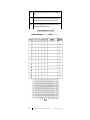
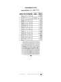
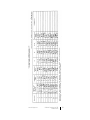
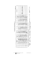
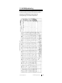
1
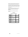
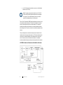
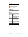
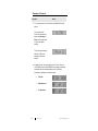
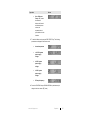
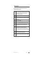
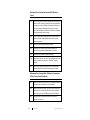
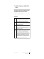
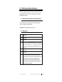
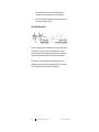
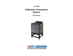
HI-2790B Calibration Comparison System User Manual ETS-Lindgren Inc. reserves the right to make changes to any products herein to improve functioning or design. Although the information in this document has been carefully reviewed and is believed to be reliable, ETS-Lindgren does not assume any liability arising out of the application or use of any product or circuit described herein; nor does it convey any license under its patent rights nor the rights of others. All trademarks are the property of their respective owners. © Copyright 2001–2014 by ETS-Lindgren Inc. All Rights Reserved. No part of this document may be copied by any means without written permission from ETS-Lindgren Inc. Trademarks used in this document: The ETS-Lindgren logo is a trademark of ETS-Lindgren Inc. Revision Record MANUAL, HI-2790B | Part # H-600092, Rev. D ii Revision Description Date A Initial Release February, 2001 B Updated Power/Control Module information; branding changes June, 2008 C Minor edits/updates June, 2011 D Minor edits to tables in Operation October, 2014 www.ets-lindgren.com Table of Contents Notes, Cautions, and Warnings ................................................ v General Safety Considerations ................................................ v 1.0 Introduction .......................................................................... 7 General Description .................................................................................... 7 HI-2790B Calibration Comparison System Block Diagram .................. 8 ETS-Lindgren Product Information Bulletin ................................................. 9 2.0 Maintenance ....................................................................... 11 Replacing the Fuse ................................................................................... 11 Service Procedures .................................................................................. 12 Contacting ETS-Lindgren .................................................................. 12 Sending a Component for Service..................................................... 12 Calibration Services and Annual Calibration...................................... 12 3.0 Setup ................................................................................... 13 Connecting Components .......................................................................... 13 4.0 Operation ............................................................................ 15 Description of Controls.............................................................................. 15 Operation of Controls ................................................................................ 16 Error Messages ........................................................................................ 18 Establishing a Reference Field.................................................................. 19 Recording Data ......................................................................................... 21 Microwave Oven Survey Instrument Daily Ellipticity Check ....................... 22 Microwave Oven Survey Meter Calibration Comparison, 30-Day Check, Initial Conditions ....................................................................................... 22 Calibration Comparison ............................................................................ 23 30-Day Comparison Requirements ........................................................... 24 5.0 Calibration Comparison Log 30-Day Check .................... 25 6.0 Calibration Comparison Log 2 dB Limitation Check ..... 29 7.0 HI-2790B Operational Log ................................................. 33 8.0 CDRH Section 8 Report Guidelines ................................. 35 8.1 Microwave Test Instruments (Type and Quantity) ............................... 35 www.ets-lindgren.com iii 8.2 Daily Check......................................................................................... 35 8.3 30-Day Constancy Check ................................................................... 36 8.4 Repair of Survey and Calibration Instruments ..................................... 37 8.5 Annual Calibration and Periodic Calibration ........................................ 37 9.0 Specifications ..................................................................... 39 Appendix A: Warranty ............................................................. 41 Duration of Warranties .............................................................................. 41 Appendix B: Declaration of Conformity ................................ 43 iv www.ets-lindgren.com Notes, Cautions, and Warnings Note: Denotes helpful information intended to provide tips for better use of the product. Caution: Denotes a hazard. Failure to follow instructions could result in minor personal injury and/or property damage. Included text gives proper procedures. Warning: Denotes a hazard. Failure to follow instructions could result in SEVERE personal injury and/or property damage. Included text gives proper procedures. Note: See the ETS-Lindgren Product Information Bulletin for safety, regulatory, and other product marking information. General Safety Considerations Warning: For indoor use only, do not expose to rain.. Note: See the ETS-Lindgren Product Information Bulletin for safety, regulatory, and other product marking information. www.ets-lindgren.com v This page intentionally left blank. vi www.ets-lindgren.com 1.0 Introduction The ETS-Lindgren HI-2790B Calibration Comparison System is an instrument calibration comparison system that can be used by microwave oven manufacturers to comply with the Center for Devices and Radiological Health (CDRH) requirements as outlined in Guide for Preparing Reports on Radiation Safety of Microwave Ovens, dated March 1985. The HI-2790B is a complete system containing all of the equipment necessary to check microwave oven survey instruments and monitor the calibration stability of these instruments. This involves checking each instrument periodically to make sure that its response is within specification, and its calibration remains constant. This must not be confused with performance of absolute calibration or transfer calibration on the instrument. In addition to defining a standard format for data, the information provided in this manual is intended to guide the oven manufacturer in establishing procedures for using the HI-2790B system to generate information for reporting to the U.S. Food and Drug Administration, Department of Health and Human Services, Center for Devices and Radiological Health. Note: The HI-2790B system replaces the HI-2790A and HI-2795A Calibration Comparison Systems. The HI-2790B system offers a broader, continuous power range from 0.1 to more than 5 mW/cm2. The internal microwave (2.45 GHz) power source offers a more stable RF signal to the test chamber. The HI-2790B Power/Control Module has a single mains input operating from 100 to 240 VAC, 50/60 Hz. General Description The HI-2790B system consists of: A portable anechoic chamber mounted on a frame with castor wheels for ease of movement. A Power/Control Module containing a crystal-controlled 2450 MHz solid state source and a power meter for monitoring power to the waveguide and forward, reflected, and transmitted power. www.ets-lindgren.com Introduction 7 An HI-1710 Microwave Survey Meter to serve as a Local Calibration Reference (HI-1710 LCR). Note: For maximum accuracy and traceability, the HI-1710 LCR and the HI-2623 Probe/Preamp Assembly must be used together as a single unit. The HI-2623 assembly should not be used for general oven leakage testing or any other purpose. The HI-1710 LCR and the HI-2790B Power/Control Module are mounted on top of the cabinet toward the rear edge. The Power/Control Module is connected directly to the waveguide through a coax cable assembly. The waveguide penetrates the chamber and terminates in a slot antenna radiating toward the probe holding fixture. The fixture is mounted in the wall directly opposite the slot antenna. The probe holding fixture is slotted so that the probe can be inserted into the chamber without removing the probe spacer cone. The fixture allows the probe under test to be rotated 360 degrees, but has adequate friction to limit axial motion. A fixture mounted on a horizontal cross-member in the chamber accurately maintains the spacing of the probe sensing head to the slot antenna. HI-2790B CALIBRATION COMPARISON SYSTEM BLOCK DIAGRAM 8 Introduction www.ets-lindgren.com ETS-Lindgren Product Information Bulletin See the ETS-Lindgren Product Information Bulletin included with your shipment for the following: Warranty information Safety, regulatory, and other product marking information Steps to receive your shipment Steps to return a component for service ETS-Lindgren calibration service ETS-Lindgren contact information www.ets-lindgren.com Introduction 9 This page intentionally left blank. 10 Introduction www.ets-lindgren.com 2.0 Maintenance CAUTION: Before performing any maintenance, follow the safety information in the ETS-Lindgren Product Information Bulletin included with your shipment. WARNING: Maintenance of the HI-2790B and HI-1710 LCR is limited to external components such as cables or connectors. Clean the exterior of the cabinet using a damp cloth and mild cleaner. Always unplug the unit before cleaning. Keep the interior of the cabinet free of any foreign objects. Warranty may be void if the housing is opened. WARRANTY If you have any questions concerning maintenance, contact ETS-Lindgren Customer Service. Replacing the Fuse Caution: Disconnect the HI-2790B and HI-1710 from power before replacing a fuse. If the HI-2790B Calibration Comparison System or HI-1710 Microwave Survey Meter (HI-1710 LCR) fails to operate, check for a blown fuse inside the power entry module. A blown fuse must be replaced with the same value and type of fuse, or an unsafe condition may result. Use only 250 Volt, 1.0 Amp, Type T (5 mm x 20 mm) fuses. To replace a fuse: 1. Two fuses are located in the fuse drawer in the power input module. Use a screwdriver to open the drawer. 2. The fuse towards the outside of the drawer is the spare. Remove the spare fuse from the module. www.ets-lindgren.com Maintenance 11 3. Replace the blown fuse with the spare fuse. 4. Slide the fuse drawer back into the module. Make sure that the drawer snaps securely into its locked position. Service Procedures CONTACTING ETS-LINDGREN Note: Please see www.ets-lindgren.com for a list of ETS-Lindgren offices, including phone and email contact information. SENDING A COMPONENT FOR SERVICE For the steps to return a system or system component to ETS-Lindgren for service, see the Product Information Bulletin included with your shipment. CALIBRATION SERVICES AND ANNUAL CALIBRATION See the Product Information Bulletin included with your shipment for information on ETS-Lindgren calibration services. 12 Maintenance www.ets-lindgren.com 3.0 Setup CAUTION: Before connecting any components, follow the safety information in the ETS-Lindgren Product Information Bulletin included with your shipment. Connecting Components See HI-2790B Calibration Comparison System Block Diagram on page 8 for a description of connections. 1. Connect the HI-2790B Power/Control Module and the HI-1710 Microwave Survey Meter (HI-1710 LCR) to the mains power supply. Note: Some models of the HI-1710 LCR provide a voltage setting switch at the power input to select 115 or 220 VAC input voltage. 2. Plug the IN connection port on the flexible coax cable assembly into the RF output connector on the HI-2790B Power/Control Module. 3. Plug the RF coax cable into the input connector on the waveguide. www.ets-lindgren.com Setup 13 This page intentionally left blank. 14 Setup www.ets-lindgren.com 4.0 Operation CAUTION: Before placing into operation, follow the safety information in the ETS-Lindgren Product Information Bulletin included with your shipment. Description of Controls The following controls on the HI-2790B Power/Control Module allow the control, adjustment, and monitoring of all functions of the HI-2790B Calibration Comparison System. Control Function POWER Turns unit on and off. RF Turns RF power to the test chamber on and off. RF LEVEL Adjusts power level up and down. CAL Sets HI-2790B Power/Control Module to calibration mode. This mode adjusts the RF Power display to read a calibrated value that matches the reading on the HI-1710 LCR. DISPLAY SELECT Selects the Operating menu or the Status menu. UP / DOWN Steps the display through the selected menu. www.ets-lindgren.com Operation 15 Operation of Controls Operation Screen 1. Turn on power to the HI-1710 LCR and the HI-2790B Power/Control Module. The two modes of the Power/Control Module that display are Operating and Status. When initially turned on, the product screen displays. The version screen displays, and then the RF power operating mode screen displays. 2. In Operating mode, the home (initial) screen is RF power. Press the UP ARROW key and the DOWN ARROW key to change the displayed parameters within the selected Operating mode. The following parameters are displayed in the Operating mode: 16 RF Power Reflected Power Forward Power Operation www.ets-lindgren.com Operation Screen Net or Difference Power—DIF power is the difference between the forward and reflected power values, and represents the net power delivered to the chamber. 3. To switch to Status mode, press the DISP SELECT key. The following parameters are displayed in the Status mode: Internal temperature +10.5 VDC system power supply voltage +6 VDC system power supply voltage +5 VDC system power supply voltage RF output frequency 4. Press the UP ARROW key and DOWN ARROW key simultaneously to change to the home screen (RF power). www.ets-lindgren.com Operation 17 Error Messages Note: There are no user serviceable error messages. The HI-2790B Power/Control Module continually monitors the power supply voltages, the forward and reflected power levels, and the phase lock loop. If any of these readings fall outside the correct operating range of the unit, the unit will turn off the RF power and display one of the following messages: 10.5V LO 10.5V HI 6V LO 6V HI 5V LO 5V HI REF HI FOR HI LOCK LOST RESET If an error message appears, turn the HI-2790B Power/Control Module off to reset the unit, and then turn it on again. If the error message persists, return the unit to ETS-Lindgren for service. 18 Operation www.ets-lindgren.com Establishing a Reference Field 4.1.1 Position the HI-1710 LCR sensing probe in the probe holder with the rear of the probe head firmly seated against the end of the holding fixture. Insert the end of the probe handle into the probe holder and tighten the thumbscrew. 4.1.2 Select the 0–2 mW/cm2 range, FAST response (Filter 2), and the PEAK HOLD selection to OFF (PEAK HOLD LED is not lit). 4.1.3 Turn on the RF switch and adjust the RF LEVEL until approximately 1.00 mW/cm2 is displayed on the HI-1710 LCR. 4.1.4 Allow the system to stabilize for ten minutes with the RF switch on. 4.1.5 Rotate the probe in the probe holder, noting the highest reading and the lowest reading in one full rotation of the probe. Using the highest and lowest observed readings, rotate the probe to obtain a reading exactly midway between the high and low reading. Alternately, a mark can be made on the probe handle to allow repositioning the probe at the same point for all 30-day comparisons. 4.1.6 With the probe adjusted or rotated for a mid reading, readjust the RF LEVEL to obtain an indication on the HI-1710 LCR of 1.00 mW/cm2. 4.1.7 Make sure the Power/Control Module is displaying RF Power. If not sure, press the UP and DOWN keys simultaneously to change the display to the RF Power indication. 4.1.8 Calibrate the HI-2790B Power/Control Module RF Power reading by pressing and holding the CAL button, and then pressing the UP or DOWN buttons until the Power/Control display indicates the same value as the HI-1710 LCR (typically 1.00). 4.1.9 With the RF power on and the HI-1710 LCR indicating 1.00, note the Power/Control Module in the FWD, REF, and DIF readings and record in the operational log. Rotate the probe through one complete revolution and record the highest and the lowest readings. Check the ZERO condition of the HI-1710 LCR and rezero if necessary. The HI-2790B system is now ready to perform calibration checking. www.ets-lindgren.com Operation 19 20 4.1.10 Check the system field level at 1 mW/cm2 by placing the HI-1710 LCR probe in the chamber and aligning the probe at its midpoint reading. 4.1.11 Remove the HI-1710 LCR probe and place it in its holder on top of the system. 4.1.12 This ends the setup procedure for the HI-2790B system. The information logged in step 4.1.9 on page 19 must be reviewed to make sure that the HI-2790B system remains stable. No value of the DIF or the RF Power reading may be lower than 10% less than the highest reading observed over a 12-month period between annual calibrations of the HI-1710 LCR. If a reading falls below these limits, carefully review and repeat the setup procedure. If it is still outside the limits, check the rest of the data for indications of the problem area. The HI-1710 LCR bias, ellipticity, and the ambient temperature readings should also remain within specified limits. Operation www.ets-lindgren.com Recording Data Record the following data in a permanent log similar to the example HI-2790B Operational Log on page 33. 4.2.1 Each log should identify the HI-2790B Power/Control Module serial number and the serial numbers of the HI-1710 LCR and HI-2623 Probe/Preamp Assembly. 4.2.2 Date. 4.2.3 Power/Control Module FWD, REF, DIFF, and RF Power readings (at 1.0 mW/cm2). 4.2.4 HI-1710 LCR bias voltage. 4.2.5 HI-1710 LCR ellipticity values (maximum, minimum, and mean). 4.2.6 Ambient temperature and Power/Control Module internal temperature. 4.2.7 The REMARKS column, in addition to noting unusual observations, should identify whether daily checks or 30-day checks are being performed, the type of instrument being checked, and so on. 4.2.8 Power/Control Module RF Power (at mW/cm2). 4.2.9 The person performing the test should be identified in the Initial column. www.ets-lindgren.com Operation 21 Microwave Oven Survey Instrument Daily Ellipticity Check 4.3.1 Zero the instrument to be checked, making sure the access door is closed or the RF switch is off. Insert the probe of the instrument to be measured into the HI-2790B probe holding fixture. Make sure the probe is properly located against the stop on the holding fixture. Set the scale of the instrument to that used for compliance testing (usually the 0-2 mW/cm2 range). 4.3.2 Turn RF POWER switch on and adjust the RF LEVEL control to obtain a mid-scale reading (approximately 1 mW/cm2) on the meter being checked. 4.3.3 Rotate the probe to obtain the minimum reading. 4.3.4 Readjust the RF POWER control so that the meter on the instrument being checked indicates precisely 1.0 mW/cm2. 4.3.5 Rotate the probe to obtain the maximum reading. 4.3.6 If this value is less than 1.10 mW/cm2, the calibration status of the meter is acceptable. If greater than 1.10 mW/cm2, it may be rejected. 4.3.7 Record in a permanent log the daily checks on all instruments, indicating whether each instrument was accepted or rejected. Microwave Oven Survey Meter Calibration Comparison, 30-Day Check, Initial Conditions 22 4.4.1 Meters to be checked must be turned on and allowed to stabilize in accordance with the manufacturer recommendations. 4.4.2 Select the desired probe range, zero the instrument, making sure the access door is closed or the RF switch is off, and place the instrument on top of the HI-2790B system to the left of the door. 4.4.3 Place the probe in the holder as described in step 4.1.1 on page 19. Close the door. Operation www.ets-lindgren.com Calibration Comparison 4.5.1 With the Power/Control Module RF POWER set to OFF, check that the instrument being checked is properly zeroed. Turn the RF Power switch on and check that the indicated RF POWER is 1.0 mW/cm2 as established in step 4.1.9 on page 19. Rotate the probe slowly through one full revolution (360 degrees) and record the maximum and minimum readings. 4.5.2 Add the MAX reading to the MIN reading and divide the sum by two. The result is the MEAN value. 4.5.3 Subtract the MIN reading from the MAX reading, divide the result by the MEAN reading from the previous step, and then multiply this result by 100. This is the TOTAL ELLIPTICITY in percent. The maximum allowable ellipticity should be obtained from the manufacturer specifications. Enter these values into the Calibration Comparison Log. Example: The test indicates a MAX value of 1.023 and a MIN value of 0.985. Add 1.023 and 0.985. This equals 2.008. Divide 2.008 by 2. This gives a MEAN value of 1.004. Subtract the MIN value (0.985) from the MAX value (1.023). This gives a value of 0.038. Divide 0.038 by the MEAN value (1.004), and then multiply the result by 100. This gives a TOTAL ELLIPTICITY of 3.78%. www.ets-lindgren.com Operation 23 30-Day Comparison Requirements 24 4.6.1 No value of the MEAN reading of any instrument may be lower than 90% of the highest reading observed over a 12-month period between annual calibrations of the HI-1710 LCR. Any time the MEAN reading or ELLIPTICITY reading is outside the specified limits, that instrument must be rejected. It should be returned to the original manufacturer for repair and/or recalibration. Never attempt to adjust the calibration of an instrument. See Calibration Comparison Log 30-Day Check on page 25 for suggested log, examples, and forms usage instructions. 4.6.2 No two acceptable instruments shall yield readings that differ by more than 2 dB, including polarization extremes. See Calibration Comparison Log 2 dB Limitation Check on page 29 for log forms and suggested procedure. A separate 2 dB band may be used for all instruments checked on a given HI-2790B system. Operation www.ets-lindgren.com 5.0 Calibration Comparison Log 30-Day Check To make sure that microwave survey instruments are being checked in accordance with Center for Devices and Radiological Health (CDRH) guidelines, complete the Calibration Comparison Log 30 Day Check form on page 26 using the following instructions, and in conjunction with the HI-2790B Calibration Comparison System. Note: The word MEAN is used to refer to the average or center value of the polarization ellipticity reading. 5.1.1 A separate log should be kept for each instrument, identifying it by model number and serial number. 5.1.2 Record the maximum, minimum, and mean values, and calculate the ellipticity as follows: Total % ellipticity = MAX minus MIN x 100 MEAN 5.1.3 Comparison readings should always be made at the mean and for a given instrument. No reading may be lower than 10% below the highest reading during the 12-month period between annual calibrations. The first reading in a 12-month period between annual calibrations will always be acceptable if it is within the dB band for all instruments. The ellipticity must be within the manufacturer specifications. For ETS-Lindgren instruments the limit is 10% total, plus or minus 5%. Compare the mean reading and the ellipticity reading against these limits and determine acceptance or rejection. www.ets-lindgren.com Calibration Comparison Log 30-Day Check 25 26 5.1.4 The person performing the test should be identified in the INITIAL column. 5.1.5 The mean readings and/or limits may be graphically displayed as desired in the chart space provided at the bottom of the log. 5.1.6 Logs for an acceptable meter and a rejected meter are shown in the example logs on pages 27 and 28. Calibration Comparison Log 30-Day Check www.ets-lindgren.com www.ets-lindgren.com Calibration Comparison Log 30-Day Check 27 28 Calibration Comparison Log 30-Day Check www.ets-lindgren.com 6.0 Calibration Comparison Log 2 dB Limitation Check See the example logs on pages 31 and 32. Every 30 days review the results of the 30-day calibration comparison check on all meters, including the HI-1710 LCR. Note the highest (max) reading and the lowest (min) reading from all meters for the current 30-day check. This information can be obtained from the MAX and the MIN columns on the Calibration Comparison Log 30-day Check log for each meter. 6.1.1 Record the highest max and the lowest min on the Calibration Comparison Log 2 dB Limitation Check on page 31. For the first month the highest max will be A and the lowest min will be B. 6.1.2 For the future months A must be updated to the highest max and B must be updated to the lowest min. 6.1.3 Divide the highest max by the lowest min to obtain the ratio A/B. If the ratio is less than 1.59, enter Yes in the last column. If the ratio is greater than 1.59, enter No. 6.1.4 If the ratio is greater than 1.59, action must be taken to reduce the ratio A/B to less than 1.59. For example, the log on page 32 reports an unacceptable result for March 1985. It indicates a new meter introduced in January read higher than the other meters, but that all readings were within acceptable limits. In March, however, it forced the A/B ratio to exceed 1.59. Removing that meter from service dropped the A number back to its former level. www.ets-lindgren.com Calibration Comparison Log 2 dB Limitation Check 29 30 Calibration Comparison Log 2 dB Limitation Check www.ets-lindgren.com www.ets-lindgren.com Calibration Comparison Log 2 dB Limitation Check 31 32 Calibration Comparison Log 2 dB Limitation Check www.ets-lindgren.com 7.0 HI-2790B Operational Log A permanent log similar to the following HI-2790B Operational Log should be maintained for the HI-2790B Calibration Comparison System. See Recording Data on page 21 for instructions to complete the form. www.ets-lindgren.com HI-2790B Operational Log 33 This page intentionally left blank. 34 HI-2790B Operational Log www.ets-lindgren.com 8.0 CDRH Section 8 Report Guidelines Following is a suggested set of answers to Section 8 of the Center for Devices and Radiological Health (CDRH) Guide for Preparing Reports on Radiation Safety of Microwave Ovens. 8.1 Microwave Test Instruments (Type and Quantity) To be answered by each oven manufacturer. List the manufacturer, model number, and quantity of meters as requested. For example: ETS-Lindgren Model HI-1501, quantity: 13 8.2 Daily Check 8.2.1 Check Yes. 8.2.2 Check Yes. 8.2.3 Check Yes. 8.2.4 The maximum allowable polarization ellipticity for all ETS-Lindgren microwave survey meters is ± 5%, or 10% total, or 0.10 total. See the manufacturer specifications for allowable ellipticity for other models. 8.2.5 Check Yes. 8.2.6 Check Yes. 8.2.7 ETS-Lindgren Calibration Comparison System Model number (insert model number) is used for performing the daily check on all hand scan instruments. The daily check of the Automated Microwave Oven Screening System (AMOSS) is performed in accordance with the sign-on self-test criteria that are part of the operational program of AMOSS. www.ets-lindgren.com CDRH Section 8 Report Guidelines 35 8.2.8 Check Yes. 8.2.9 Check Yes. 8.2.10 Check box and supply a sample of the daily check record for a hand-held meter and a sample print-out of the AMOSS daily sign-on log form. 8.3 30-Day Constancy Check 8.3.1 Instrument Intercomparison System Manufacturer name and model number: ETS-Lindgren Model HI-2790B RF source frequency and frequency stability: 2450 MHz, ± 0.1 MHz RF source amplitude modulation: CW with approximately 1% ripple HI-1710 LCR manufacturer and model number: ETS-Lindgren Model HI-1710 Radiated Power Monitor (RPM) manufacturer and model number: N/A 36 8.3.2 Do not check this box. 8.3.3 Check Yes. 8.3.4 Check Yes. 8.3.5 A. Check HI-1710 LCR. B. Check HI-1710 LCR. 8.3.6 Check Yes. 83.7 Check Yes. 8.3.8 Check the box, enclose a copy of a page of the Operational Log from the system, and label it Attachment 8.3.8. 8.3.9 Check Yes. 8.3.10 Check Yes. CDRH Section 8 Report Guidelines www.ets-lindgren.com 8.3.11 Check Yes. 8.3.12 Check Yes. 8.3.13 Check the box, enclose a copy of the 2 dB Limitation Check Log, and label it Attachment 8.3.13. 8.3.14 Check Yes. 8.3.15 Check the box, enclose a copy of the 30-day Check Log, and label it Attachment 8.3.15. 8.4 Repair of Survey and Calibration Instruments 8.4.1 All microwave survey compliance instruments are repaired and recalibrated by ETS-Lindgren. 8.4.2 Check the box and include a copy of your procedure, and label it Attachment 8.4.2. 8.4.3 The HI-1710 LCR and Power/Control Module are repaired and recalibrated by ETS-Lindgren. 8.4.4 Check Yes. 8.5 Annual Calibration and Periodic Calibration 8.5.1 Check No and add Only the LCR. 8.5.2 Check Yes and enter annually in the blank. Note:. The oven manufacturer procedures must provide adequate documentation to back up the statements and check marks made in this section www.ets-lindgren.com CDRH Section 8 Report Guidelines 37 This page intentionally left blank. 38 CDRH Section 8 Report Guidelines www.ets-lindgren.com 9.0 Specifications Frequency: 2450 + 0.1 MHz over an ambient temperature range of 20 degrees to 24 degrees C Frequency Stability: 50 ppm/°C + 0.0025% Dynamic Range: 0.1 – 5 + mW/cm2 Plane-wave equivalent power density at probe test location. Input Power: 100 – 240 VAC 0.8 – 0.4 A max 50 – 60 Hz Fuses: 250 Volt, 1.0 Amp, Type T (5 mm x 20 mm) Output: 2450 MHz, 4 W max Do not operate without 50 ohm load. Local Calibration Reference: HI-1710 Microwave Survey System (HI-1710 LCR) Size: Width: 770 mm wide Depth: 1040 mm deep Height: 1230 mm high (1360 mm with HI-2790B Power/Control Module) Weight: 45 kg (shipping) Support: Castor wheels for ease of location www.ets-lindgren.com Specifications 39 Repeatability of Measurements: If the recommended procedures are followed, an operator can repeat measurements to plus or minus 2% (of this, plus or minus 1% will be due to the last digit uncertainty of the digital meter on the HI-1710 LCR). Inside Dimensions of Anechoic Material: 18 in x 18 in x 18 in Environmental: Operating temperature: 10 degrees to 40 degrees C Humidity: 5% to 95% relative humidity, non-condensing Power Cable: This unit is shipped with a three-wire power cable that meets or exceeds the requirements of EN60799. When this cable is connected to an appropriate AC power source, it connects the chassis to earth ground. The type of power cable shipped with each unit depends on the country of destination. Note: The power cable used must be rated for a minimum of 250V/10A. 40 Specifications www.ets-lindgren.com Appendix A: Warranty Note: See the Product Information Bulletin included with your shipment for the complete ETS-Lindgren warranty for your HI-2790B Calibration Comparison System. Duration of Warranties All product warranties, except the warranty of title, and all remedies for warranty failures are limited to one year. Product Warranted Duration of Warranty Period HI-2790B Calibration Comparison System 1 Year www.ets-lindgren.com Warranty 41 This page intentionally left blank. 42 Warranty www.ets-lindgren.com Appendix B: Declaration of Conformity Factory Issued by ETS-Lindgren L.P. ETS-Lindgren L.P. 1301 Arrow Point Drive Cedar Park, TX, USA 78613 1301 Arrow Point Drive Cedar Park, TX, USA 78613 ETS-Lindgren L.P. declares under sole responsibility that the: Model / Part Number: HI-2790B Model / Part Name: Calibration Comparison System Date of Declaration: April 19, 2001 to which this declaration relates, meets the requirements and is in conformity with the relevant EC Directives listed in the following using the relevant section(s) of the EC harmonized standards and other normative documents: APPLICABLE DIRECTIVE(S) Low Voltage Directive (LVD), 73/23/EEC and its amending directives Electromagnetic Compatibility Directive (EMC), 89/336/EEC and its amending directives APPLICABLE HARMONIZED STANDARDS(S) AND/OR NORMATIVE DOCUMENT(S) EN 61000-3-2:1995 Electromagnetic Compatibility (EMC) – Part 3: Limits Section 2: Limits for harmonic current emissions (equipment input current less than or equal to 16 A per phase) EN 61000-3-3:1995 Electromagnetic Compatibility (EMC) – Part 3: Limits Section 3: Limitation of voltage fluctuations and flicker in low-voltage supply systems for equipment with rated current less than or equal to 16 A EN 61010-1: Safety requirements for electrical equipment for measurement, control, and laboratory use – Part 1: General requirements (IEC 1010-1 : 1990 + A1 : 1992, Modified) www.ets-lindgren.com Declaration of Conformity 43 EN 61326:1997 (Amendment A1: 1998) Electrical equipment for measurement, control, and laboratory use – EMC requirements EN 61326-1:1997 Electrical equipment for measurement, control, and laboratory use—EMC requirements AUTHORIZED SIGNATORIES The authorizing signatures on this Declaration of Conformity document authorize ETS-Lindgren L.P. to affix the CE mark to the indicated product. CE marks placed on these products will be distinct and visible. Other marks or inscriptions liable to be confused with the CE mark will not be affixed to these products. ETS-Lindgren L.P. has ensured that technical documentation shall remain available on premises for inspection and validation purposes for a period ending at least 10 years after the last product has been manufactured. 44 Declaration of Conformity www.ets-lindgren.com