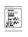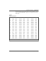
1
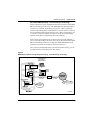
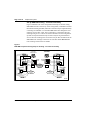
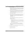
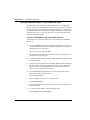
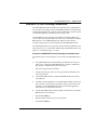
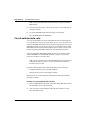
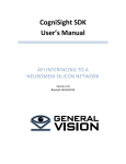
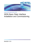
Meridian 1
ISDN Basic Rate Interface
Acceptance Testing
Document Number: 553-3901-330
Document Release: Standard 6.00
Date: April 2000
Year Publish FCC TM
Copyright © 1992–2000 Nortel Networks
All Rights Reserved
Printed in Canada
Information is subject to change without notice. Nortel Networks reserves the right to make changes in design
or components as progress in engineering and manufacturing may warrant. This equipment has been tested
and found to comply with the limits for a Class A digital device pursuant to Part 15 of the FCC rules, and the
radio interference regulations of Industry Canada. These limits are designed to provide reasonable protection
against harmful interference when the equipment is operated in a commercial environment. This equipment
generates, uses and can radiate radio frequency energy, and if not installed and used in accordance with the
instruction manual, may cause harmful interference to radio communications. Operation of this equipment in a
residential area is likely to cause harmful interference in which case the user will be required to correct the
interference at their own expense.
SL-1 and Meridian 1 are trademarks of Nortel Networks.
ISDN Basic Rate Interface
Acceptance Testing
4
Page 3 of 36
Revision history
April 2000
Standard 6.00. This is a global document and is up-issued for X11 Release
25.0x. Document changes include removal of: redundant content; references
to equipment types except Options 11C, 51C, 61C, and 81C; and references
to previous software releases.
October 1997
Issue 5.00 released for Generic X11 Release 23.0x.
August 1996
Issue 4.00 released for Generic X11 Release 22.0x.
December 1995
Issue 3.00 released as Standard for Generic X11 Release 21.1x.
Note: No issue 2.00 was released.
December 1994
Issue 1.00 released as Standard for Generic X11 Release 20.0x.
July 1994
Standard version issued for Generic X11 Release 19.0x.
July 1993
Standard version issued for Generic X11 Release 18.0x.
ISDN Basic Rate Interface
Acceptance Testing
Page 4 of 36
553-3901-330
Standard 6.00
April 2000
Page 5 of 36
Contents
About this guide . . . . . . . . . . . . . . . . . . . . . . . . . . .
7
Prepare the system . . . . . . . . . . . . . . . . . . . . . . . . .
9
Test ISDN BRI functions . . . . . . . . . . . . . . . . . . . . .
15
Generate traffic reports . . . . . . . . . . . . . . . . . . . . .
33
ISDN Basic Rate Interface
Acceptance Testing
Page 6 of 36
Contents
553-3901-330
Standard 6.00
April 2000
8
Page 7 of 36
About this guide
Content List
The following are the topics in this section:
•
About this guide 7
•
Related documents 8
About this guide
This document describes acceptance testing of ISDN BRI services for
Meridian 1 system Options 11C, 51C, 61C, and 81C. Acceptance testing is
conducted after the equipment has been installed and configured to verify that
the system is operating correctly and ISDN BRI functions and features work
as specified. It describes how to visually inspect ISDN BRI equipment for
possible improper installation, how to interpret visual indicators on ISDN
BRI cards, and how to test basic ISDN BRI features and verify traffic
reporting.
This document is a global document. Contact your system supplier or your
Nortel Networks representative to verify that the hardware and software
described is supported in your area.
Note: When reading this document, please note the following:
•
ISDN BRI trunking is not supported in North America
•
the Basic Rate Signaling Concentrator (BRSC) is not supported on
Option 11C
•
the integrated Meridian 1 Packet Handler is not supported on
Option 11C.
ISDN Basic Rate Interface
Acceptance Testing
Page 8 of 36
About this guide
Related documents
553-3901-330
•
ISDN Basic Rate Interface: Product Description (553-3901-100)
•
ISDN Basic Rate Interface: Installation (553-3901-200)
•
ISDN Basic Rate Interface: Administration (553-3901-300)
•
ISDN Basic Rate Interface: Maintenance (553-3901-500)
Standard 6.00
April 2000
14
Page 9 of 36
Prepare the system
Content List
The following are the topics in this section:
•
Reference List 9
•
Introduction 9
•
Verify ISDN BRI operation 10
•
Set up ISDN BRI test terminals and trunks 10
Reference List
The following are the references in this section:
•
ISDN Basic Rate Interface: Installation (553-3901-200)
•
ISDN Basic Rate Interface: Administration (553-3901-300)
•
ISDN Basic Rate Interface: Maintenance (553-3901-500)
Introduction
This chapter describes how to prepare ISDN BRI equipment for acceptance
testing. It explains how to verify that ISDN BRI cards are enabled and
functioning correctly and how to correct any problems before starting the test.
ISDN Basic Rate Interface
Acceptance Testing
Page 10 of 36
Prepare the system
Verify ISDN BRI operation
After ISDN BRI equipment has been installed and configured, you can
visually inspect ISDN BRI cards to make sure that they are operating
correctly by observing their LEDs:
•
Check the red Dis LED located on the MISP faceplate. If the Dis LED on
an MISP is lit, check that the MISP is disabled or faulty. If it is
extinguished, check that the MISP is enabled and operating. To enable
the MISP or to correct a problem, refer to ISDN Basic Rate Interface:
Maintenance (553-3901-500).
•
Check the red LED located on the BRSC faceplate. If the red LED is
extinguished, check that the BRSC is enabled and operating correctly. If
the red LED is lit, check that the BRSC is manually disabled or faulty.
To enable a BRSC or to correct a problem, refer to ISDN Basic Rate
Interface: Maintenance (553-3901-500).
•
Check the red LED located on the SILC and UILC faceplates. If the red
LED is extinguished, check that the SILC or UILC is enabled and
operating correctly. If the red LED is lit, check that the SILC or UILC is
manually disabled or faulty. To enable an SILC or a UILC or to correct
a problem, refer to ISDN Basic Rate Interface: Maintenance
(553-3901-500).
If all indicator LEDs on ISDN BRI equipment are extinguished (with the
exception of the CC LED on a MISP), the equipment is functional and you
may proceed with setting up the terminals you wish to use for this test.
Set up ISDN BRI test terminals and trunks
Set up ISDN BRI terminals
To conduct acceptance testing for ISDN BRI terminals, you must have a setup
that can verify basic ISDN BRI functions and features. Figure 1 shows an
example of the ISDN BRI terminal arrangement. You may wish to establish
a different test setup, which may be determined by the type of terminals
implemented in a specific customer configuration. You may want to set up
communication between ISDN BRI and non-ISDN terminals.
Refer to the ISDN Basic Rate Interface: Installation (553-3901-200) for
ISDN BRI terminal installation instructions.
553-3901-330
Standard 6.00
April 2000
Prepare the system
Page 11 of 36
Perform acceptance testing
To perform acceptance testing of ISDN BRI terminals:
•
select three digital subscriber loops (DSLs), two connected to different
SILCs and one to a UILC.
•
equip each SILC DSL with two voice, one circuit-switched data, and one
low speed packet data ISDN BRI terminals.
Note: Packet data testing can be conducted only if an external packet
handler or an MPH is installed as part of the customer configuration, and
is supported by the Meridian 1 (like the external DPN-100 packet
handler). If packet handler is not part of the configuration, do not equip
the DSLs with packet data terminals and skip all the packet data tests
specified in this chapter.
•
equip the UILC DSL with a network terminator (NT1) and connect the
two voice and one circuit-switched data ISDN BRI terminal to the S/T
interface on the NT1.
•
configure the DSLs to support these ISDN BRI terminals and initialize
the terminals as described in the “Initialize ISDN BRI terminals” section
of the ISDN Basic Rate Interface: Administration (553-3901-300).
After you have completed the setup to perform acceptance testing, you can
proceed with the tests described in the next chapter.
ISDN Basic Rate Interface
Acceptance Testing
Page 12 of 36
Prepare the system
Figure 1
ISDN BRI acceptance testing setup for terminals
CPU
System Memory
CPU Bus
Network Bus
Superloop
Network
Card
MISP
PRIas
MISP
PRIas
BRIL
MPH
Network
PRI
Card
S/T Interface
Controller
Card
PRI
SILC
PRI
Terminating
resistor
Peripheral Bus
S/T Interface
BRSC
PRI
UILC
PRI
SILC
PRI
U Interface
NT1
S/T Interface
553-7706
553-3901-330
Standard 6.00
April 2000
Prepare the system
Page 13 of 36
Set up ISDN BRI trunking - Local Exchange connectivity
Figure 2 illustrates a typical configuration that may be used for testing ISDN
BRI Local Exchange connectivity. The ISDN BRI Local Exchange DSL is
connected to a Network Termination (NT1) device, which is physically
located on the same premises as the Meridian 1. The NT1 device connects to
the Local Exchange that supports Numeris VN2, 1TR6 or D70 protocol via a
U interface. The distance limitation of the NT1 from the Local Exchange
depends on the distance supported by the Local Exchange.
System clock synchronization may be achieved by having the Meridian 1
slave to the local exchange; the clock source may be derived either the ISDN
BRI Local Exchange connection or from other ISDN BRI/PRI/DTI local
exchange connections if available for the test environment.
After you have completed the setup to perform acceptance testing, you can
proceed with the test described in the next chapter.
Figure 2
ISDN BRI acceptance testing setup for trunking - Local Exchange connectivity
Non ISDN BRI device
such as 2500 or
digital type telephone
Non ISDN
PRI
BRI
Line Card
ISDN BRI
terminal
equipment
S/T
SILC
PRI
S/T
Clock Controller
Slave
PRI
Maximum 1 km
(0.6 miles)
NT1
U
Maximum 5.5 km
(3.3 miles)
Central
Office
supporting 1 TR6,
Numeris VN2, D70
ISDN
BRI/DT12/PR12
connection
553-7707
Meridian 1
ISDN Basic Rate Interface
Acceptance Testing
Page 14 of 36
Prepare the system
Set up ISDN BRI trunking - Tie trunk connectivity
Figure 3 illustrates one of the configurations that may be used for testing
ISDN BRI Tie trunk connectivity. In this configuration, a Meridian Customer
Defined Networking (MCDN) TIE trunk connection may be implemented by
connecting two Meridian 1s to the ISDN BRI leased line through the local
exchange via two SILC cards. The S/T interface is connected to the local
exchange using an NT1. There is no distance limitation on this configuration.
System clock synchronization may be achieved by having the Meridian 1
slave to the local exchange; the clock source may be derived either from the
ISDN BRI local exchange connections or from other ISDN BRI/PRI/DTI
local exchange connections if available.
Figure 3
ISDN BRI acceptance testing setup for trunking - Tie trunk connectivity
Non ISDN BRI device
such as 2500 or
digital type telephone
Non ISDN BRI device
such as 2500 or
digital type telephone
Non ISDN
PRI
BRI
Line Card
Non ISDN
IRP
BRI Line Card
ISDN BRI
terminal
S/T
ISDN BRI
terminal
S/T
SILC
IRP
SILC
PRI
S/T
U
NT1
Local
Exchange
S/T
U
NT1
Clock Controller
Clock Controller
Slave
PRI
ISDN
BRI/DT12/PR12
connection
ISDN
BRI/DT12/PR12
connection
Meridian 1
553-3901-330
Standard 6.00
Slave
Meridian 1
April 2000
553-7672
32
Page 15 of 36
Test ISDN BRI functions
Content List
The following are the topics in this section:
•
Reference List 16
•
Introduction 16
•
Voice calls 16
•
Call hold 17
•
Call waiting 18
•
Call Forward No Answer 19
•
Calling Line Identification Presentation and Restriction 20
•
ISDN BRI Conference (National ISDN-1 and ETSI) 21
•
ISDN BRI Special Hunting 24
•
ISDN BRI National ISDN-1 Call Forward All Calls 26
•
ISDN BRI ETSI Call Forwarding Unconditional 27
•
Circuit-switched data calls 28
•
Packet data transmission 29
•
Test an ISDN BRI trunk 32
•
Remove the test setup 32
ISDN Basic Rate Interface
Acceptance Testing
Page 16 of 36
Test ISDN BRI functions
Reference List
The following are the references in this section:
•
ISDN Basic Rate Interface: Administration (553-3901-300)
•
X11 Administration (553-3001-311)
Introduction
This chapter describes some ISDN BRI functional tests used to verify the
operation of ISDN BRI equipment. The tests include basic call connections,
voice and data transmission, and verification of some Meridian 1 features
using ISDN BRI terminals. Testing of an ISDN BRI trunk DSL is also
included.
The tests are divided into:
•
voice calls
•
circuit-switched data calls
•
B-channel and D-channel packet data calls, using an external packet
handler and an MPH
•
ISDN BRI trunk
Voice calls
A voice call can be established between two voice terminals across a network
(ISDN or non-ISDN), between two terminals on the same Meridian 1, and
between two terminals on the same DSL. Acceptance testing of ISDN BRI
voice calls is conducted when testing the following system features supported
by ISDN BRI terminals.
553-3901-330
•
Call hold
•
Call waiting
•
Call Forward No Answer
•
Calling Line Identification Presentation and Restriction
•
ISDN BRI National ISDN-1 Conference and Call Join
•
Special ISDN BRI Hunting
•
ISDN BRI ETSI Conference
Standard 6.00
April 2000
Test ISDN BRI functions
•
ISDN BRI ETSI Call Forwarding Unconditional
•
ISDN BRI National ISDN-1 Call Forward All Calls
Page 17 of 36
Call hold
Call hold is used to place an active call on hold to allow answering an
incoming call or placing an outgoing call. After releasing an incoming or an
outgoing call, retrieve the call on hold.
Note: The following test requires the terminal placing the calls on hold
to have multiple DN appearances. Otherwise, this test cannot be
performed as written.
Perform a call hold test
1
From an ISDN BRI terminal, dial an ISDN BRI or a non-ISDN BRI
terminal and establish an active call connection.
2
Verify that voice transmission is established by talking with the person
at the other terminal.
3
Press the HOLD key to place the active call on hold.
Note: To find out how to use the feature keys on different ISDN BRI
terminals, consult the user manual that is supplied with the terminal.
4
Place an outgoing call by dialing an idle ISDN BRI or a non-ISDN BRI
terminal.
5
Complete this outgoing call and hang up.
6
Have another ISDN BRI or non-ISDN BRI terminal call while the first
call is still on hold.
7
Answer the incoming call and place it on hold.
8
Retrieve the call first held.
9
Complete the call and hang up.
10 Retrieve the second call on hold.
11 Complete the call and hang up.
ISDN Basic Rate Interface
Acceptance Testing
Page 18 of 36
Test ISDN BRI functions
This test can be repeated for terminals connected to the same DSL, different
DSLs on the same card, different DSLs on cards associated with different
MISPs/BSRCs, and between ISDN BRI and non-ISDN BRI terminals.
Call waiting
Call waiting informs an ISDN BRI terminal user engaged in an active call that
a call is waiting to be answered. A call setup message is sent to a DSL when
both B-channels are busy and an incoming call is in progress. This causes a
warning tone to the terminal speaker. To accept the new call, the user must
place the currently active call on hold or release the call.
Call waiting is activated only if Hunting is not enabled or fails to handle the
incoming call. The incoming call may originate from an ISDN BRI or a
non-ISDN BRI terminal.
Note: The following test requires that the terminal receiving the second
(call waiting) call has multiple DN appearances. Otherwise, this test will
fail.
Perform a call waiting test
1
Set the FEAT parameter to HTD to disable hunting. Use LD 27 to
specify this parameter when configuring the TSP for the two voice ISDN
BRI DNs on one of the DSLs. See “TSP configuration procedures” in
ISDN Basic Rate Interface: Administration (553-3901-300).
2
From an ISDN BRI terminal with disabled hunting, dial another ISDN
BRI terminal and establish an active call connection.
3
From the second ISDN BRI terminal with disabled hunting, dial another
ISDN BRI terminal and establish another active call connection. Both
B-channels on the DSL are now busy.
Note: Only two ISDN BRI terminals may be on the same DSL to allow
them to connect. The other two ISDN BRIs are on a different DSL.
553-3901-330
4
Place an incoming call to one of the busy ISDN BRI terminals with
disabled hunting.
5
Observe the called ISDN BRI terminal. The ringing or warning tone
should sound, indicating that a call is waiting.
6
Place the active call on hold and answer the call that is waiting.
Standard 6.00
April 2000
Test ISDN BRI functions
7
Complete the incoming call and hang up.
8
Retrieve the call on hold.
9
Complete the call and hang up.
Page 19 of 36
Call Forward No Answer
Call Forward No Answer and Second Level Forward No Answer forwards an
unanswered call to a Call Forward No Answer Directory Number (DN) after
a predetermined number of rings. This feature is enabled at the TSP level
when defining the ISDN BRI DN. Both the external and internal Call Forward
No Answer features are configured at the DSL level using LD 27. The call
can be specified to be forwarded to the attendant, to an assigned hunting DN,
or to a flexible Call Forward No Answer DN by using LD 15.
When a call originated by an ISDN BRI terminal is forwarded to a
predetermined DN specified in LD 15, the display on that ISDN BRI terminal
is not updated to indicate a call modification.
Perform a Call Forward No Answer test
1
Set the FEAT parameter to FNA and SFA to enable Call Forward No
Answer and Second Level Forward No Answer. (SFA is needed only to
test two levels of Call Forward No Answer.) Use LD 27 to specify these
parameters when configuring the TSP for one of the two voice ISDN BRI
terminal DNs. See “TSP configuration procedures” in ISDN Basic Rate
Interface: Administration (553-3901-300).
2
Specify the attendant as the forwarding DN using LD 15. At the FNAL
prompt, enter ATT to specify forward to attendant. Refer to LD 15 in the
X11 Administration (553-3001-311) for more details.
3
From an ISDN BRI terminal, place a call to the ISDN BRI terminal with
the enabled Call Forward No Answer feature and the specified call
forward to attendant.
4
Do not answer the call. After a predetermined number of rings, the call
is forwarded to the attendant. The display on the call-originating ISDN
BRI terminal will not be updated to indicate that the call has been
modified and forwarded to the attendant.
ISDN Basic Rate Interface
Acceptance Testing
Page 20 of 36
Test ISDN BRI functions
5
Verify the call was forwarded to the attendant by answering the call at
the attendant console. The attendant console will display the
call-originating identification number and the notification of call
redirection.
6
Hang up at the call-originating ISDN BRI terminal to release the call
connection.
Calling Line Identification Presentation and Restriction
Calling Line Identification Presentation and Restriction allows a calling party
number (calling line identification) to be shown on a called party ISDN BRI
terminal display. Use LD 27 to specify this feature when configuring the TSP
for the ISDN BRI terminal DN. See “TSP configuration procedures” in ISDN
Basic Rate Interface: Administration (553-3901-300).
This feature gives the calling and the called parties the option of displaying
the calling line identification as follows:
•
The called party ISDN BRI terminal must have the calling line
presentation (CLIP) parameter value set to YES to accept the calling line
identification and show it on its display.
•
If there is an option on the ISDN BRI terminal which enables the calling
party to allow or restrict the presentation of the calling line ID on a per
call basis, select the option to allow presentation. This option on the
terminal overrides the PRES parameter values entered in the TSP data
block when configuring the TSP. This depends on the telephone
configuration default. See “TSP configuration procedures” in ISDN
Basic Rate Interface: Administration (553-3901-300).
Perform a Calling Line Identification Presentation test
553-3901-330
1
Configure both the calling and the called party ISDN BRI terminal DN
with CLIP = YES and PRES = YES.
2
Place a call from one terminal to the other and observe the display on the
called party ISDN BRI terminal. The calling line identification should be
displayed during ringing and for the duration of the call.
3
Release the call at the called or calling party terminal.
Standard 6.00
April 2000
Test ISDN BRI functions
Page 21 of 36
4
Set PRES = NO in the TSP data block for the calling party ISDN BRI
terminal. If the calling party ISDN BRI terminal has an option on the set
to allow or restrict the presentation of the calling party number, select the
option to allow presentation and place a call to another ISDN BRI
terminal.
5
Observe the called party ISDN BRI terminal display. You should see the
number being displayed.
6
Release the call connection.
ISDN BRI Conference (National ISDN-1 and ETSI)
ISDN BRI Conference allows an ISDN BRI terminal user to bridge multiple
parties into a conversation. The user can:
•
invoke Conference on a call
•
add a new party to an existing call
•
Call Join two separate parties on the terminal
•
disconnect him/her self from the Conference
Perform an ISDN BRI Conference test
Note: The same procedures may be used to test ISDN BRI NI-1 or ETSI
Conference.
1
In the DSL configuration in LD 27, set PRID = 6 to select the National
ISDN-1 protocol, or set PRID = 2 for the ETSI protocol.
2
In the TSP configuration in LD 27, define conference under FEATID:
FEATID aaa mmm <nnn>, where
aaa = A03 (3-party conference) or A06 (6-party conference)
mmm = feature activation ID (0 - 127)
nnn = feature indication ID (0 - 127) (If nnn is not entered, it is assumed
to be the same as mmm)
3
Select National ISDN-1 or ETSI protocol on the ISDN BRI terminal if
signaling type/protocol is configurable.
4
On the ISDN BRI terminal, configure Conference. This procedure
largely depends on the implementation of feature key management on
individual terminals. In general:
ISDN Basic Rate Interface
Acceptance Testing
Page 22 of 36
Test ISDN BRI functions
•
The terminal provides Conference as a selectable feature to be
programmed on a hard/soft key. For example, on a soft key on an
M5317TDX, select FA to be FCC; on a hard key on an M5209TDcp,
select CONF.
•
The Conference key number selected on the terminal must correspond to
the feature activation ID entered for the TSP in LD 27.
5
Configure at least two DN appearances on the ISDN BRI terminal. On
some ISDN BRI terminals, the second DN appearance allows the user to
initiate the second call.
6
Place an outgoing call from the ISDN BRI terminal.
7
After the call is established, press the Conference key. The first call is put
on hold automatically; a second key is lit to allow the user to place the
second call.
8
Place another outgoing call from the second key.
9
After the second call is established, press the Conference key again to
bridge the two calls. All three parties should be in a conference.
10 Press the RELEASE key to drop from the call. The ISDN BRI user
should be disconnected from the Conference; the remaining two parties
should still be connected, for two outgoing trunk calls, in which case all
parties should be disconnected.
Perform a Call Join test on Conference
1
In the DSL configuration in LD 27, set PRID = 6 to select the National
ISDN-1 protocol, or PRID = 2 for ETSI protocol.
2
In the TSP configuration in LD 27, define conference under FEATID:
FEATID aaa mmm <nnn>, where
aaa = A03 (3-party conference) or A06 (6-party conference)
mmm = feature activation ID (0 - 127)
nnn = feature indication ID (0 - 127) (If nnn is not entered, it is assumed
to be the same as mmm)
3
553-3901-330
On the ISDN BRI terminal, if the signaling type/protocol is configurable,
then select National ISDN-1or ETSI protocol.
Standard 6.00
April 2000
Test ISDN BRI functions
Page 23 of 36
4
On the ISDN BRI terminal, configure Conference. This procedure
largely depends on the implementation of feature key management on
individual terminals. In general:
•
The terminal provides Conference as a selectable feature to be
programmed on a hard/soft key. For example, on a soft key on an
M5317TDX, select FA to be FCC; on a hard key on an M5209TDcp,
select CONF.
•
The Conference key number selected on the terminal must correspond to
the feature activation ID entered for the TSP in LD 27
5
Configure at least two DN appearances on the ISDN BRI terminals. On
some ISDN BRI terminals, the second DN appearance is used to allow
the user to initiate the second call.
6
Place an outgoing call from the ISDN BRI terminal.
7
After the first call is established, place an incoming call to the ISDN BRI
terminal.
8
Hold the first call and answer the second call.
9
Press the Conference key; the second call is put on hold.
10 Retrieve the first call and press the Conference key again. All three
parties should be in a conference.
11 Press the RELEASE key to drop from the call. The ISDN BRI user
should be disconnected from the conference; the remaining two parties
should still be connected, except for two outgoing trunk calls, in which
case all parties should be disconnected.
ISDN Basic Rate Interface
Acceptance Testing
Page 24 of 36
Test ISDN BRI functions
ISDN BRI Special Hunting
ISDN BRI Special Hunting allows a call encountering a destination that has
a call in progress to be automatically routed to a different destination in a hunt
chain. Hunting continues along a predetermined sequence of DNs in a
hunting group until an idle ISDN BRI or non-ISDN BRI terminal DN is found
or until the maximum number of hunt steps is exhausted. Use LD 27 to define
the hunting DNs in the DSL. See “DSL configuration procedures” in ISDN
Basic Rate Interface: Administration (553-3901-300).
Special hunting for ISDN BRI supports calls terminating at an ISDN BRI
terminal. This feature is activated when a call terminating at a DSL
encounters a busy condition and if hunting is enabled. Internal and external
hunt DNs can be specified when configuring the DSL.
A busy condition occurs:
•
if the maximum number of calls on a DSL exceeds the specified limit of
calls on a DSL including active, calls held, calls waiting, and calls in
progression (as configured on LD 27), or
•
if the total number of calls including active, calls held, calls waiting, and
calls in progress exceeds the number of channels configured to handle
the incoming call type
If the call limit on a DSL is not exceeded, an incoming call is presented to the
DSL interface as a call waiting call. If Hunting is enabled, the call will be
hunted.
Use LD 27 to enable or disable Hunting when configuring the TSP for the
ISDN BRI terminal DN. See “TSP configuration procedures” in ISDN Basic
Rate Interface: Administration (553-3901-300).
553-3901-330
Standard 6.00
April 2000
Test ISDN BRI functions
Page 25 of 36
Perform a hunting test
1
Set the FEAT parameter to HTA to enable hunting for two voice ISDN
BRI terminals. Use LD 27 to specify this parameter when configuring the
TSP. See “TSP configuration procedures” in ISDN Basic Rate Interface:
Administration (553-3901-300).
2
Use LD 27 to specify the HUNT parameter DNs when configuring the
DSL. These hunt parameter DNs specify the members of a hunting chain.
See “DSL configuration procedures” in ISDN Basic Rate Interface:
Administration (553-3901-300).
3
Place two calls, one for each voice ISDN BRI terminal, on a DSL to
create a DSL busy condition.
4
Place a voice call to one of the busy ISDN BRI terminals with hunting
enabled. Since the channel type required to handle the incoming call type
is busy, hunting is automatically invoked to find an idle DN in the
hunting chain.
The following may occur:
•
If the call finds an idle voice ISDN BRI or non-ISDN BRI terminal, it
will ring that terminal.
•
If hunting is not successful:
— the originating party receives a busy tone if the total number of calls
on the DSL (as configured on LD 27) exceeds the maximum number
of calls allowed, or
— the call is placed in call waiting if the maximum number of calls on
the DSL is below the specified limit
•
If the call is placed in call waiting, observe the called ISDN BRI
terminal. You should get a visual indication of the next DN, and receive
an audible tone.
5
Place the active call on hold and answer the incoming call that is waiting.
6
Complete the incoming call and hang up.
7
Retrieve the call on hold.
8
Release the call connection.
ISDN Basic Rate Interface
Acceptance Testing
Page 26 of 36
Test ISDN BRI functions
ISDN BRI National ISDN-1 Call Forward All Calls
National ISDN-1 Call Forward All Calls enables a user of an ISDN BRI
terminal to have calls redirected from the user’s directory number to another
directory number. Calls are redirected regardless of the busy or idle status of
the interface to the user. Call Forward is assigned on the basis of the directory
number and call type (i.e., the user may have voice calls forwarded, while
data calls terminate normally).
Perform an ISDN BRI NI-1 Call Forward All Calls test
The following is to test the forwarding of a voice call from an ISDN BRI
M5317 set.
553-3901-330
1
Set up ISDN BRI NI-1 Call Forward All Calls in Overlay 27 (refer to the
“Configuring ISDN BRI features” chapter in ISDN Basic Rate Interface:
Administration (553-3901-300)).
•
select the NI-1 protocol for the DSL;
•
configure the Call Forward All Calls feature ID for a particular DN and
call type (enter voice call type).
2
On the ISDN BRI terminal, configure ISDN BRI National ISDN-1 Call
Forward All Calls.
3
Configure two DN appearances on the ISDN BRI terminal (use the first
DN to forward a call, and the second DN to place a call to test the call
forward). On some ISDN BRI terminals, the second DN appearance
allows the user to initiate the second call.
4
Activate ISDN BRI National ISDN-1 Call Forward All Calls on the
ISDN BRI terminal, for the first DN:
•
Press the Forward key.
•
Dial the number where calls are to be forwarded.
•
Press the Forward key.
5
From the second DN, place a call to the first DN, to verify that the call
ha been forwarded.
6
To cancel National ISDN-1 Call Forward All Calls:
•
Press the Forward or the Cancel key.
Standard 6.00
April 2000
Test ISDN BRI functions
Page 27 of 36
ISDN BRI ETSI Call Forwarding Unconditional
The ISDN BRI ETSI Call Forwarding Unconditional (CFU) supplementary
service allows an incoming call to an ISDN BRI terminal to be forwarded to
a predetermined destination, within or outside the Meridian 1 system. The call
is forwarded regardless of whether the user is busy or idle.
An ISDN BRI user can assign the same address or a different address for
voice or data calls being forwarded. Calls can also be forwarded to an ISDN
BRI terminal or a non-ISDN BRI terminal. When the CFU feature is
activated, outgoing calls can still be made from the ISDN BRI terminal.
The ETSI supplementary service provides Call Forwarding capabilities to all
users on the access (i.e., all the DNs defined under a Digital Subscriber Loop
(DSL)), or an individual user (i.e., a DN).
Perform an ISDN BRI ETSI Call Forwarding Unconditional test
The following test is for forwarding a voice call from an ISDN BRI M5317
set.
1
Set up ISDN BRI ETSI Call Forwarding Unconditional in Overlay 27
(refer to the “Configuring ISDN BRI features” chapter in ISDN Basic
Rate Interface: Administration (553-3901-300)).
•
select the ETSI protocol for the DSL;
•
configure the call type (enter voice call type) and Call Forward (enter
voice call forward).
2
On the ISDN BRI terminal, configure ISDN BRI ETSI Call Forward
Unconditional.
3
Configure two DN appearances on the ISDN BRI terminal (use the first
DN to forward a call, and the second DN to place a call to test the call
forward). On some ISDN BRI terminals, the second DN appearance
allows the user to initiate the second call.
4
Activate ISDN BRI ETSI Call Forwarding Unconditional on the ISDN
BRI terminal, for the first DN:
•
Press the Forward key.
•
Dial the number where calls are to be forwarded.
•
Press the Forward key.
ISDN Basic Rate Interface
Acceptance Testing
Page 28 of 36
Test ISDN BRI functions
Note: Call Forward Reminder Tone should be provided to the ISDN
BRI terminal.
5
From the second DN, place a call to the first DN, to verify that the call
ha been forwarded.
6
To cancel ISDN BRI ETSI Call Forwarding Unconditional:
•
Press the Forward or the Cancel key.
Circuit-switched data calls
A circuit-switched data call can be established between two data terminals
over a B-channel. The call is set up the same way as a voice call. Dial a call
using the ISDN BRI terminal key pad or keyboard depending on the type of
ISDN BRI terminal used. After the connection is established and the called
ISDN BRI terminal sends an acknowledgment that it is ready to receive data,
the call-originating ISDN BRI terminal can start transmitting user data.
If the call-originating ISDN BRI terminal requests access to data stored in
another ISDN BRI or non-ISDN BRI terminal, it may have to provide a
password to be able to access that data.
Note: Follow the instructions in the ISDN BRI terminal user manual for
a detailed description of how to set up a call connection and how to
transmit and receive data.
In general, data terminals are divided into the following two categories:
•
intelligent terminals such as personal computers
•
dumb terminals such as video display terminals
Repeat this test on several terminals including both intelligent and dumb
terminals as needed.
Perform a circuit-switched data call test
553-3901-330
1
From an ISDN BRI data terminal, dial another ISDN BRI data terminal
and establish an active call connection.
2
After receiving an acknowledgment that the other terminal is ready,
begin transmitting data.
Standard 6.00
April 2000
Test ISDN BRI functions
Page 29 of 36
3
Verify that the transmitted data has been received successfully by
checking transmitted information for accuracy. Read the information on
the screen or print it on the local printer.
4
Release the connection.
Packet data transmission
A packet data call can be established between two data terminals over a
B-channel or a D-channel.
B-channel packet data terminals communicate with the packet handler at 64
kbps over dedicated B-channels. The packet handler may be an external
packet handler, the DPN-100, or the integrated MPH. The packet handlers
processes and distributes the data to local terminals for local calls or over the
packet data network for remote calls.
D-channel packet data terminals communicate at a baud rate of up to
9.6 kbps. The packet data is multiplexed onto a 64 kbps BD that is linked with
the external packet handler through a dedicated ISDN PRI B-channel, or, in
the case of the MPH, through a dedicated connection.
Note: To perform packet data transmission verification, the system must
be connected to a DPN-100, or configured with Meridian Packet Handler
(MPH). Also, packet data transmission functions must be selected when
configuring the B-channel and D-channel transmission characteristics.
Use LD 27 to specify the packet data transmission functions. See “MISP
configuration procedures” in ISDN Basic Rate Interface: Administration
(553-3901-300)
In addition to configuring the MISP and the DSL using LD 27, be sure of the
following.
•
the ISDN PRI loop carrying packet data was configured using LD 17
•
the packet handler route was specified using LD 16
•
an ISDN PRI channel for the packet handler route was configured using
LD 14
See ISDN Basic Rate Interface: Administration (553-3901-300) for a detailed
description of how to configure relevant ISDN BRI packet data transmission
parameters using LD 17, LD 16, and LD 14.
ISDN Basic Rate Interface
Acceptance Testing
Page 30 of 36
Test ISDN BRI functions
Perform a B-channel packet data transmission test using an
external packet handler
1
From an ISDN BRI B-channel packet data terminal, dial another local or
a remote ISDN BRI packet data terminal and establish an active call
connection.
2
After the call-originating ISDN BRI terminal receives an
acknowledgment that the receiving ISDN BRI terminal is ready, the
call-originating ISDN BRI terminal can begin transmitting packet data.
3
Verify that the transmitted data has been received successfully by
checking the transmitted information for accuracy. Read the information
on the screen or print it on the local printer.
4
Release the connection.
Repeat this test on other ISDN BRI packet data terminals as needed.
Perform a D-channel packet data transmission test using an
external packet handler
553-3901-330
1
From an ISDN BRI D-channel packet data terminal, dial another ISDN
BRI packet data terminal and establish an active call connection.
2
After the call-originating ISDN BRI terminal receives an
acknowledgment that the receiving ISDN BRI terminal is ready, the
call-originating ISDN BRI terminal can begin transmitting packet data.
3
Verify that the transmitted data has been received successfully by
checking the transmitted information for accuracy. Read the information
on the screen or print it on the local printer.
4
Release the connection.
Standard 6.00
April 2000
Test ISDN BRI functions
Page 31 of 36
Perform a D-channel Switched Virtual Circuit packet data
transmission test using an MPH
1
From an ISDN BRI D-channel packet data terminal, dial another local
ISDN BRI packet data terminal or a remote packet data terminal
(depending on how you have configured your MPH application).
Establish an active call connection.
2
After the call-originating ISDN BRI terminal receives an
acknowledgment that the receiving ISDN BRI terminal is ready, the
call-originating ISDN BRI terminal can begin transmitting packet data.
3
Verify that the transmitted data has been received successfully by
checking the transmitted information for accuracy. Read the information
on the screen or print it on the local printer.
4
Perform this test between two ISDN BRI terminals on the same MPH for
local transmission and between a Meridian 1 ISDN BRI terminal and a
remote ISDN BRI terminal over the Packet Switched Data Network
(PSDN).
5
Release the connection.
Perform a B-channel Switched Virtual Circuit packet data
transmission test using an MPH
1
From an ISDN BRI B-channel packet data terminal, dial the Network
Terminal Numbers (NTNs) as configured in LD 27. Establish an active
call connection.
2
After the call-originating ISDN BRI terminal receives an
acknowledgment that the receiving ISDN BRI terminal is ready, the call
originating ISDN BRI terminal can begin transmitting packet data.
3
Verify that the transmitted data has been received successfully by
checking the transmitted information for accuracy. Read the information
on the screen or print it on the local printer.
4
Perform this test between two ISDN BRI terminals on the same MPH for
local transmission and between a Meridian 1 ISDN BRI terminal and a
remote ISDN BRI terminal over the packet data network.
5
Release the connection.
ISDN Basic Rate Interface
Acceptance Testing
Page 32 of 36
Test ISDN BRI functions
Test an ISDN BRI trunk
Perform the following procedure to test an ISDN BRI trunk DSL.
1
Set up the ISDN trunk test configuration to be used, as described
previously in the chapter “Set up ISDN BRI test terminals and trunks”.
2
Place a call across the ISDN BRI trunk.
3
Complete the call and hang up.
Remove the test setup
After acceptance testing has been completed and the results show the system
is operating correctly, remove the ISDN BRI terminal setup and configure
ISDN BRI equipment according to the customer configuration. If the actual
customer configuration was used to perform these tests, no changes are
needed.
553-3901-330
Standard 6.00
April 2000
36
Page 33 of 36
Generate traffic reports
Content List
The following are the topics in this section:
•
Reference List 33
•
Introduction 33
Reference List
The following are the references in this section:
•
ISDN Basic Rate Interface: Administration (553-3901-300)
Introduction
This chapter describes how to generate traffic reports to verify that the traffic
generated during voice and data transmission testing has been stored by the
system and can be printed on demand.
To verify traffic generated during acceptance testing, use the following
command.
INVS (options)*
The asterisk (*) denotes that the ENTER key must be pressed after the desired
option numbers are entered.
ISDN Basic Rate Interface
Acceptance Testing
Page 34 of 36
Generate traffic reports
Reports are generated using one or more of the following option numbers.
Option
Meaning
1
Network traffic report
11
ISDN BRI MISP and/or BRSC traffic
report
12
ISDN BRI MISP and/or BRSC
D-channel management messages
report
13
ISDN BRI MISP and/or BRSC
messages report
14
Trunk DSL system traffic report
15
MPH traffic report
For example, to verify ISDN BRI traffic generated during acceptance testing,
select the network traffic report and the MISP traffic report as follows.
INVS 1 11
The system printer should print these two reports. Check the reports to make
sure the traffic generated during the test is reflected in the reports.
553-3901-330
Standard 6.00
April 2000
Generate traffic reports
Page 35 of 36
The network traffic report shows the traffic activities for Meridian 1 lines and
trunks including ISDN BRI DSLs. Figure 4 is an example of the Network
traffic report.
Figure 4
Network traffic report
0111 TFS000
004
TERM
00000
0000120
00090
00000
0000535
00300
008
TDS
00000
0000050
00060
00000
0000200
00100
012
CONF
00001
0000010
00020
00003
0000090
00080
016
TERM
00000
0000000
00000
00000
0000000
00000
020
TERM
00000
0000200
00093
00000
0000980
00800
024
TERM
00000
0000005
00030
00000
0000039
00034
028
CONF
00000
0000030
00040
00000
0000090
00080
032
TERM
00000
0000080
00030
00000
0000235
00230
036
TERM
00000
0000070
00050
00000
0000450
00300
040
TDS
00000
0000070
00050
00000
0000226
00131
044
TERM
00002
0000060
00051
00003
0000120
00100
048
TERM
00000
0000070
00060
00000
0000240
00200
052
TERM
00000
0000030
00222
00000
0000100
00094
056
TERM
00000
0000080
00075
00000
0000450
00400
Note: DSLs are included in TERM type.
ISDN Basic Rate Interface
Acceptance Testing
Page 36 of 36
Generate traffic reports
For a detailed description of how to set up and print traffic reports, see “Set
up ISDN BRI traffic reports” in ISDN Basic Rate Interface: Administration
(553-3901-300).
553-3901-330
Standard 6.00
April 2000
Family Product Manual Contacts Copyright FCC notice Trademarks
Document number Product release Document release Date Publish
Meridian 1
ISDN Basic Rate Interface
Acceptance Testing
Copyright © 1992– 2000 Nortel Networks
All Rights Reserved
Information is subject to change without notice. Nortel
Networks reserves the right to make changes in
design or components as progress in engineering and
manufacturing may warrant. This equipment has been
tested and found to comply with the limits for a Class A
digital device pursuant to Part 15 of the FCC rules,
and the radio interference regulations of Industry
Canada. These limits are designed to provide
reasonable protection against harmful interference
when the equipment is operated in a commercial
environment. This equipment generates, uses and can
radiate radio frequency energy, and if not installed and
used in accordance with the instruction manual, may
cause harmful interference to radio communications.
Operation of this equipment in a residential area is
likely to cause harmful interference in which case the
user will be required to correct the interference at their
own expense.
SL-1 and Meridian 1 are trademarks of Nortel
Networks.
Publication number: 553-3901-330
Document release: Standard 6.00
Date: April 2000
Printed in Canada