1
4878
4:7
$
52.25
SUMMER
1983
i
SYNDLE
The Electronic Candle
that flickers like
a Wax Taper
The magazine
f
:r
build electronic projects
people who
MAKE PRO CABINETS
for Home-Brew Projects
Buîid it for TUN
3 -Band Shortwave Converter
lectronic Slot Machine
Preamplifier for moving coil
_
Phono Cartridge
Soundbox -80 for Computer
Game Sounds
Prototyping Power Supply
crest Gear 'Projects
See page 4
W
Ribbon -Cable Tester
Meg -O- Dapter for DVM
Mini -Audio Generator
See page 61
Scope Calibrator
Single Sweeper -One Blanker
See page
'PLUS....
JBL Sound System
for the musician!
See page 42
See page 4
NOW YOUR SINGLE SOURCE FOR ALL YOUR ELECTRONIC
CIRCUIT BUILDING, TESTING AND INTERCONNECTION NEEDS.
Introducing Our Ccmpfete Line of
Interconnection Products and
Accessories...Fea- aring Our New
Insulation Displacement Connectors.
No matter what your requirements in
interconnection proaucts, w have just what
you are looking for. DIP, Socket, and Card E ge 1DC connectors, all styles and sizes
Headers and D- Submin i-r both IDC and
sc'der versions. Also flat cable in both gray
f
an rainbow in a wide range of widths.
Brand New Low Cost IDC Assembly Tool
So sLnsationally low- price.I it won'_ put a
crimp" n your budgct.
VW'
145A
Famous A P Quality and Price
Every A P product is bui_t with time -pros e
quality and dependability. And best cf
all.. .each one is very competitively priced.
Your Single Source
A P makes hunireds of electronic circuit
building and testing devices as well as
a complete line of interconnection
products and accessories Everything from
Breadboards, Super -Strips. Test Clips
and Poweraces to Headers, Connectors
and Cable.
A P has it all for you!
; g
I
A P PRODUCTS INCORPORATED 9450 Pineneedle Drive P 0. Box 540 Mentor, Ohio 44060.1216)354-2101. TWX:
In Europe, contact A P PRODUCTS GrrbHBaeumlesweg 21
D -7031 Wei: 1
West Germany
810- 425 -2250
For she name of your nearest distributor call Toll Free 800 -321 -9668. (In Ohio call collect 216 -354 -2101.)
a
_r
'11014t -CARD
1:
Ra dio-
Electronics
s1eo
The Magazinre for people
e
#7
SUMMER 1983
who build electronic gadgets!
You made us believers!
Editors sit in ivory palaces and conjure up ideas, stories, features, and
everything else that goes into magazines. Far too often, an editor will
forget about the real world his readers live in and drift off into some
fantasy world that is not meaningful to them. Here at Special Projects
we realize that human attribute, and work hard to avoid the pitfalls that
grow in every editor's path.
In an editorial discussion period two issues back, it was decided that
our readers wanted to receive Special Projects via subscription-let the
mailman do the walking. We had no hard facts to back up our dream, but
we believed we were correct in that assumption. After a few inquiries via
the telephone, we asked our readers in the last issue to advise us as to
what we should do. You made us believers in ourselves! You voted
overwhelmingly for the subscription option. So be it!
If you wish to subscribe to Special Projects, we suggest you turn to
page 7, where complete subscription information and a coupon to facilitate ordering is available.
For the remainder of 1983, Special Projects will be a quarterly magazine. We are still looking into the possibility of publishing more frequently,
but that move has to be based on so many facts, and inputs from so many
corners, that the decision to remain quarterly will have to stand for the
present. One source of input is you, our readers. Let's hear from you.
Shou.'d we continue to publish quarterly? Or, should we step up to
bi- monthly -six issues a year? Your input makes our decisions meaningful. Pease help us.
Now, all we ask you to do it turn the page and get into this issue of
Special Projects. Enjoy reading it, and enjoy building projects, as much
as WE have enjoyed preparing the issue for you. The Editor's Choice for
this issue is Syndle -the Electronic Candle, which appears on page 61. If
you'd like to learn Morse code, turn to page 93 for complete plans for a
code -practice processor that we call CPP1. And, there is lots more to pick
from ühat'll make Special Projects your benchside manual for many
months to come. Happy building.
Hugo Gernsback (1884 -1967) founder
M. Harvey Gernsback, editor -in-chief
Larry Steckler, CET, publisher
Art Kleiman, editorial director
Julian S. Martin, KA2GUN
managing editor
Josef Bernard, K2HUF,
technical editor
Carl Laron,associate editor
Brian C. Fenton, assistant editor
Dan Rosenbloom,
production manager
Robert A. W. Lowndes, production
associate
Joan Roman, circulation director
Arline
R. Fishman,
advertising coodinator
Cover photo by Robert Lewis
Composition and interior design by
Mates Graphics
BUSINESS AND EDITORIAL OFFICES
Gernsback Publications, Inc.
200 Park Ave. S., New York, NY 10003
President: M. Harvey Gernsback
Vice President; Larry Steckler
ADVERTISING SALES
Stanley Levitan
Radio -Electronics
200 Park Ave., South
New York, N.Y., 10003
212- 777 -6400
PACIFIC COAST
Mountain States
Marvin Green
Radio-Electronics
413 So. La Brea Ave.
Los Angeles, Ca 90036
(213) 938 -0166
MIDWEST/Texas/
Arkansas /Okla.
Ralph Bergen
The Ralph Bergen Co.
540 Frontage Road -Suite 325
Northfield, Illinois 60093
(312) 446-1444
Julian S. Martin, KA2GUN
Managing Editor
-
Radio -Electronics Special Projects, (ISSN 0730 -7616) published quarterly by Gernsback Publications, Inc., 200 Park
U.S. funds only. Canada
Avenue South, New York, NY 10003. Phone 212 -777 -6400. Four -issue subscription rate is $9.00
and Mexico subscribers add $3.00 for postage. All others add $7.00. Mail all subscription orders, address changes,
correspondence and Postmaster Notices of undelivered copies (Form 3579) to Special Projects Subscription Service, Suite
1101, 200' °ark Avenue South, New York, NY 10003. Single-copy price $2.25. © 1983 by Gemsback Publications, Inc. All
rights reserved. Printed in U.S.A.
A stamped self- addressed envelope must accompany all submitted manuscripts and/or artwork or photographs if their return
is desired should they be rejected. We disclaim any responsibility for the loss or damage of manuscripts and /or artwork or
photographs while
in
our possession or otherwise.
products, techniques and scientific and technological
a servize to readers, Radio- Electronics Special Projects publishes available plans or Information relating to newsworthy
any
developments. Because of possible variances in the quality and condition of materials and workmanship used by readers, Radio-Electronics Special Projects disclaims
responsibility for the safe and proper functioning of reader-built projects based upon or from plans or information published In this magazine.
As
RadioEleotronios
Volume
;-
..
*
-
20
DIGITAL
Here's the benchtop project for
you! It delivers 5 -volts DC that's
rock stable, has a LED -bar, current monitor, two logic -probe circuits, and 12 clock frequencies
from 0.01 to 170K Hertz.
32
34
MOCO
PREAMPLIFIER
That new flat ribbon cable may
look real good but somewhere
in one of the end connectors or
in between may lurk a short or
open circuit that'll put your
computer on hold. Our gadget
tests the biggest of cables.
lSOUNDBOX
SYSTEM
RIBBON CABLE
TESTER
GENERATOR
-- >
--
When the title of a story says as
much as this title does, what more
can be said than: Turn to page 54 for
all the facts'?
-
m
S
JBL
EM
This project is more to the liking of
a carpenter, but with our complete
construction details you can
assemble a loudspeaker system
especially designed for professional musicians. This 300-watt
project is suitable for use with lead
guitars, vocalists, and keyboards.
83
69
ELECTRONIC
SLOT
MACHINE
Here's a gaming project that
lets you keep the winnings as
player or builder- because you
own the slot machine. It's a
fun project to build.
87
SCOPE
CALIBRATOR
Here are three squarewave voltages -5.0 -, 0.5and 0.05 -volts peak -topeak -that serve as a
calibration signal for
scope's low- capacity input
probe.
your,
9sov#
SINGLE
SWEEPER ONE
your golden -oldie oscilloscope
lacking a built -in, single -sweep,
blanking circuit? Then have we
got a winner for you! All that the
old scope need have is a gate or
ramp output, and a Z -axis
input-and away you go!
Is
ELEC
8 NIC
FLASHER
Here's an opportunity to remove that clicking, stone -age
thermo-mechanical turn -signal
flasher from your car and add a
beeping, solid -state device
whose flash frequency is not
dependent on engine speed.
ÁIE
MEG-O-DAPTER
If you are getting into insulation
testing, then this project will replace the expensive Megohm
meters (called Meggers) at a f ractionn of the cost. You can test resistance at DC levels as high as
1000 volts at safe current -levels of
only 50 to 60 microamperes.
92
PRO CABINETS
FOR HOMEBREW
PILOT LIGHT
The old breadboard (Mom's
chopping board) and the oatmeal box are no longer used to
assemble projects.
For once, someone has considered the battery drain that pilot
lights place on projects. Now, a
simple circuit flashes a light emitting diode.
PROJECTS
Cattbnror
42
-ro
RETROFITTING THE
SINCLAIR /TIMEX
COMPUTER FORA
STANDARD VIDEO
OUTPUT
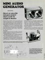
We tout this one -chip, test -gear
project as one that's worth its
weight in Hertz's. It can deliver
from 2 to 18,000 Hertz with an
output up to 10 volts peak-topeak. And it goes together faster than you can imagine-.
?..:.
electrons hitting the monitor's
screen? Well, here is a gadget
that'll interface with your computer and add sounds as you
shoot down aliens.
54
51UDIO
k7
Are your TRS -80 computer
game programs as quiet as
Have you been staying away
from moving -coil cartridges because they require very low
noise preamplifiers? Don'tbecause we have a super low -noise circuit
that uses matched quality transistors, that
provides the gain you need without hum.
MINI
-
1, No. 7
EXTRA -LOWPOWER
!-MR!1
The Magazine for people who build electronic gadgets!
CONTENTS /INDEX
TEST EQUIPMENT PROJECTS
9
Digital Prototyping System -for bench -top
Experimenters
32 Ribbon Cable Tester
24
CUSTOM SOUND
FOR YOUR CAR
That Detroit or Tokyo hunk of
iron and plastic you call "transportation" could stand an up -lift
in the radio -audio department
considering that the old heap is
going to pile up more than six digit mileage.
Z-AX1S
SWEEP
IA
40
e
OUT
REM
ON
9
SINOU
OWN
COMPUTER
CABLES
We tell you how to assemble
your own multi -lead cables, including those very expensive
pre -assembled ribbon jobs,
with the greatest of ease.
48
SUPER
"If
OF
28
MAKE YOUR
ONU
SENSITIVE
SIMPLE
VOLTMETER
III
oscilloscope
48 Super Sensitive Simple Voltmeter
Mini Audio Generator for all sound
51
systems
75 Meg -O- Dapter- checks out insulation
resistance
83 Scope Calibrator
PROJECTS FOR THE FUN OF IT
20 Soundbox -80 -add sound to TRS -80
games
24 Custon Sound for Your Car
61 Syndle -the Electronic Candle
69 Electronic Slot Machine
98 455 -kHz Beat Frequency Oscillator
61
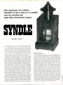
SYNDLE
The flickering light of a candle has
fascinated man throughout the
centuries. Now you can do the
same without fear of burning yourself or losing the house, by using
an electronic candle that simulates
the flame's characteristics. To turn
it off, you may try to blow it out!
42 Single Sweeper One -step -up your
Did you ever think that you
could measure the voltage on
the AGC bus without interrupting the receiver's circuit action.
This test circuit can do it and
let you read as low as
2 millivolts.
79
THREE BAND
SHORTWAVE
CONVERTER
COMPUTER PROJECTS
28 Make Your Own Computer Cables
54 Retrofitting the Sinclair /Timex Computer
for a standard video output
-for
93 CPP1 Code Practice Processor
and stepping -up Hams
PROJECTS YOU CAN'T PASS UP
-for
34 MoCo (Moving Coil) Preamplifier
audio Buffs
58 Electronic Flasher for Your Car
65 JBL System for Musicians-you build the
enclosure
Pull in the hottest shortwave
bands -49 -, 41- and 31meters -plus U.S. time
station WWV with this all -FET,
tunable converter.
93
CPP1
CODE -PRACTICE
PROCESSOR
Now you can learn the differences
between the dahs and dits, and
pick up the required code speed to
get your Amateur Radio ticket from
a single -chip processor.
98
455 -kHz
BEATFREQUENCY
OSCILLATOR
Crystal -controlled, count -down
circuit helps you tune to the
carrier with accuracy, providing
BCB listeners with a new tool.
new
79 Three -Band Shortwave Converter
87 Pro Cabinets for Home-Brew Projects
92 Extra - Low -Power Pilot Light
DEPARTMENTS
Editorial -news on how to Subscribe
4 New Products
1
Coverage Cover
8 Advertising Index
5
our Readers
101 Postage -Paid Free Information Cards
8 Letters from
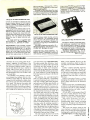
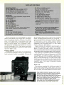
NEW PRODUCTS
ADAPTER, is an RS232 interface adapter for
the Zenith model ZTI personal- information
terminal. The ZTI terminal contains an integral 300 -baud modem for communicating
with computers over telephone lines. This
new interface allows it to function also as an
RS232 terminal to communicate with com-
puters at the user's site.
The interface plugs in between the ZTI
keyboard and power supply, supporting all
data rates available from the ZTI (110 through
2400 baud). The retail price of the RS232
adapter is $69.00.
Magnolia Microsystems, Inc., 2264 15th Ave., West, Seattle,
WA 98119.
-
CIRCLE 820 ON FREE INFORMATION CARD
RADAR WARNING,The Bearfinder Quest,
provides a four -step relative distance information display, using LED signal- strength
indicators. The first indicator and
MAGNO
CIRCLE 818 ON FREE INFORMATION CARD
accompanying slow audible beep announces
the acquisition of the radar signal. The
second, third, and fourth indicators each illuminate when a motor vehicle has traversed
one-half the remaining distance to the radar
source. As each indicator illuminates, the audible beep becomes faster and faster. When
the last indicator illuminates, the sound is
steady, warning that the radar source is near.
The Bearfinder Quest receives both X- and
K -band signals from all types of radar, including moving and hand-held pulse types. It is
designed for installation on the sunvisor or on
the dash of a motor vehicle. The small, compact case is just 5- inches wide, 13/4- inches
high, and 4- inches deep, is made of extruded
aluminum, and weighs approximately one
pound. It is available only from the factory,
and comes with plastic carrying case, velcro
square for attachment to the dash, visor düp,
instructions, and a one -year warranty. The
price is $239.00.
Bearfinder Co., Inc., 324
North Dixie Drive, Vandalia, OH 45377.
-
POWER SUPPLIES, the QPS Series, are in
low -profile design featuring two flush
mounting surfaces for easy installatiorr in
OEM applications.
QPS models have an input of 115 -volts AC
± 10 %, 47- 400Hz. Voltage /current ratings
are 5 to 24 volts, at 3 amperes. Some features of the QPS series include infinite resolution adjustments, adjustable foldback current
a
Radio-Electronics BOOKSTORE
Build Your Own Satellite TV Receiver
8 -Ball Satellite TV Antenna
Build Your Own Robot
TV Descrambler (January. February 1981)
LI Video Entertainment (January 1982)
Your Own Computer (October 1981)
Radio- Electronics back issues (1983)
(January, February 1983 not available)
Write in issues desired
Radio-Electronics back issues (1982)
(January 1982 not available)
Write in issues desired
$7.00
Radio -Electronics back issues (1981)
(March, December 1981 not available)
$5.00
$12.00
Write in issues desired
$3.00
$2.00
$3.00
$3.00
LI
Special Projects (Winter 1980)
Special Projects (Spring 1981)
Special Projects #4 (Summer 1982)
Special Projects #5 (Winter 1983)
$4.00
... ....
$4.00
$3.00
ri Special
$3.00
$4.00
.
Projects #6 (Spring 1983)
Radio -Electronics Annual 1983
$3.00
All About Kits
$2.50
$2.00
$2.00
Modern Electrics (Vol. 1. #1
$2.25
CIRCLE 819 ON FREE INFORMATION CARD
$4.95
limit, no overshoots on turn on /turn oft or
power failure, and lowest output deratings
How to Make PC Boards
April 1908)
order any of the items indicated above, check off the ones
you want. Complete the order form below, include your payment, check or money order (DO NOT SEND CASH), and mail
to Radio -Electronics, Reprint Department, 200 Park Ave.
To
South, New York. NY 10003.
with temperature. Computer -grade components are used exclusively. Transformers
use the UL- recognized Class B insulallion
ARTICLE
Please allow 4 -6 weeks for
MONTH
delivery.
II
Wireless & Electrical Cyclopedia
(1918) (176 pp)
YEAR
you need a copy of an article that is in an issue we indicate is
unavailable you can order it directly from us. We charge 50¢
per page. Indicate the issue (month & year), pages and article
PAGES
desired. Include payment in full, plus shipping and handling
charge.
MAIL
TO
@ 50k each
TOTAL PAGES
TOTAL PRICE
Radio -Electronics
SP -7
Reprint Department, 200 Park Ave. South, New York, NY 10003
Sales Tax (New York State Residents only)
$
Shipping & Handling (U.S. & Canada only) (Includes FIRST CLASS POSTAGE) $1.00 per item
All other ($2.00 per item, sea mail)
$
($4.00 per item, air mail)
$
Total Enclosed
$
Name
Address
Slate
All models in the series are UL478recognized and are 100% tested before shipment. All carry a 3 -year transferable warranty, and each of the single- output linear power
supply units is priced at $19.95.
Deltron,
Inc., PO Box 1369 Wissahickon Awe.,
NorthWales, PA 19454.
-
All payments must be in U.S. funds
Total price of order
City
system.
Zip
STEREO PROCESSOR, model 6140, takes
audio sub -carrier signals from a satellite receiver and decodes them for use with an
ordinary home -stereo receiver system. It will
also allow monaural audio sub-carriers to be
heardthrough hi -fi speakers for added enjoyment of satellite video programming.
Decoding of separate, multiplex, or matrix
stereo is accomplished via front -panel pushbutton selectors. Two independent luring
cable programs, video -games, VCR's,
Videodiscs, satellite receivers, or home computers at their fingertips.
The model VS -6004 also allows the viewer
to monitor and edit programs being recorded
on a VCR or copied from one VCR to another.
High -isolation switching circuits reduce in-
drives microcomputers bananas, and many
systems even create their own pollution. Disks and printers often create enough electrical
interference to disrupt an entire program;
nearby electronics equipment can be
affected as well.
CIRCLE 821 ON FREE INFORMATION CARD
controls are provided for selecting the sub carrier channel desired in the range of
5.5MHz to 8.0MHz. A selectable IF filter allows reception of high -fidelity programming,
with low distortion.
For tuning favorite stations easily, four independently pre -set positions may be
selected using the PROGRAM switch. Popular
sub -carrier frequencies have been preprogrammed at the factory on all four of those
positions. The TUNE position on the switch
allows the user to select alternate sub carriers.
The model 6140 has a suggested retail
Channel Master, Diviprice of $359.00.
sion of Avnet, Inc., Ellenville, NY 12428.
-
VIDEO SWITCH, model VS -6004, provides
an inexpensive way to control all TV or Video signal sources connected to a TV set from
one convenient location. By simply flipping a
switch, up to four signal sources may be
attached to a TV set and two to a VCR. Viewers will have easy access to off-the -air or
CIRCLE 822 ON FREE INFORMATION CARD
teraction between signal sources, and prevent interference. The completely passive
device requires no AC power to operate, and
is compact and lightweight. Bandpass is
Channels 2 through 83; all connections are
75 -ohm type.
The model VS -6004 is priced at $41.75.
Winegard Company, 3000 Kirkwood Street,
PO Box 1007, Burlington IA 52601.
-
COMPUTER POLLUTION CONTROL, The
Magnum Isolator, is designed to control severe electrical pollution. Electrical pollution
CIRCLE 823 ON FREE INFORMATION CARD
The Magnum Isolator incorporates heavyduty spike /surge suppression and features
four individually quad -Pi filtered AC sockets.
It will control pollution for an 1875 -watt load;
each socket can handle a 1000 -watt load.
The Magnum Isolator is priced at $200.95.
Electronic Specialists, Inc., 171 So.
Main St., PO Box 389, Natick, MA 01760.
(More on page 6)
-
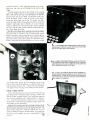
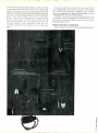
COVER COVERAGE
Probably the most exciting phase of preparing a magazine for publication is the
generation of a suitable cover picture to tell
our newsstand magazine readers what we
have to offer them in the issue. And that is
exactly what we have done on our cover.
However, we did use a few props to dress up
the photographic scene, and I'd like to tell
you about them.
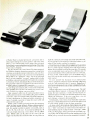
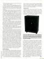
Our publisher, Larry Steckler, came upon an unusual tool cabinet (Item A) marketed by Concept 2001, Inc. that gave him
visions of a tidy workbench at home where
the tools he used most often would always
be in reach. He dug into his pocket and
made the purchase on the spot-that's inpulse buying. When I saw the tool cabinet, I
experienced impulse larceny! However, the
best I could do was borrow the unit for the
A
cover shot of this issue of Special Projects.
The photo reveals that decorative, washable, plastic tool cabinet with an assortment
of brackets and clips holding all sorts of
tools -many of which you'll recognize.
Should you care to obtain more information
on the Concept 2001 cabinets and accessories, circle number 872 on the Postage -Paid
Free Information Card bound in the back of
this issue.
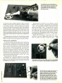
OK Industries, Inc. was kind enough to
loan to us their model SA -3 Temperature
Controlled Soldering System (Item G). It
looks like something that NASA designed,
and works as well as their space shuttles, so
I decided to use it on this issue's cover. A
fingertip control on the SA -3 Hermits accurate and useful temperature regulation of the
soldering tip whereby the experimenter has
the required heat necessary to solder IC's
onto boards and remove #14 solid copper
wire from chassis ground lugs. Now, the
need for more than one soldering iron on the
bench, or the dangerous replacement of hot
screw-in soldering tips, has been eliminated. What I like best about the SA -3 is the
feature of reducing the heat on the tip to a
low value when the soldering sequence is
interrupted, and then setting the temperature to the desired level for getting back to
work quickly. The SA -3 makes sense and
OK makes it. Want more information? Then
circle Number 873 on the Postage -Paid Free
Information Card and mail it today.
The other equally attractive items on the
cover are projects made by our authors.
What is more important: We give you the
complete construction details so that you
can make your own! Here's the lowdown on
each:
-a
battery- operated electronic
Syndle
candle (Item C) that looks like the real
thing. it flickers and dims at a random rate.
it is the kind of mood -setter you would add
to any room in your home to create an
atmosphere. That is the Editor's Choice for
this issue.
clever
Digital Prototyping System
packaging of two probes, clock outputs, and
power supply (Item B) for the test -bench
designer.
Single Sweeper One -an advanced project (Item F) for the digital experimenter and
serviceman who still is using yesterday's
oscilloscope that does not feature a single sweep blanking circuit.
455-kHz BFO
mini -project (Item D)
that you've talked about but never really
undertook to assemble. Now you have no
excuse -we give you the complete plans.
-a
-a
Mini Audio Generator-At last, a
pocket -size device (Item E) for
troubleshooting audio systems, providing
frequencies throughout and beyond the
listener's frequency range with output -level
control.
That covers the projects found on the
cover, but there's so much more in this issue
that I'm sure you'll be involved with project
building until we publish our Fall 1983 issue
of Special Projects. Till then, happy build-Julian S. Martin
ing!
NEW PRODUCTS
PRINTER, model DMP -100, is a dot -matrix
printer with graphics capability. It prints 50
characters per second at 10 characters per
inch, and has a bit -image mode to allow print-
can be printed on an 8 -inch line, with underline capability. The user can select 10
characters per inch (80 columns at 27 lines
per minute) or expanded at 5 characters per
inch (40 columns). The printer measures516
X 16 x 81/4 inches and weighs 83/5 pounds. It
operates from 120 -volts AC at 60 Hz, uses 15
watts, and is U.L. listed. A ribbon cartridge is
included.
ing of fully -addressable, high- density
graphics. Using an optional screen print program, the model DMP -100 can produce detailed black- and -white graphics printouts
similar to those on the TRS-80 Color Computer screen display.
The model DMP -100 has 80 upper and
lower case 5 x 7 dot -matrix characters which
The model DMP -100 is priced at
$399.00. -Tandy Corporation /Radio
CIRCLE 824 ON FREE INFORMATION CARD
Shack, 1800 One Tandy Lane, Fort Worth,
TX 76102.
MICROCOMPUTER, the Vector -4. incorporates both 8 -bit and 16 -bit microprocessors and presents a choice of several operating systems. It calls on 16 -bit commands to
speed up selected 8 -bit operations. To provide maximum program -development
flexibility, multiple operating systems are
available for the Vector -4, including CPA,
MS -DOS, and OASIS.
The Vector -4 includes a detached key-
Radio
Elecironics.
board, conveniently located integral floppydisk drives, and a green-phosphor video display screen that is treated optically to eliminate reflection and glare.
With a single -board microcomputer design
for compactness and reliability, the Veda ,-4
comes standard with 128K of internal RAM,
expandable to 256K. Memory- mapping logic
allows the Z -80 to access the entire main
memory in 64K increments. There are also
three S -100 card slots for accommodating
SPECIAL REPRINT
BUILD A BACKYARD SATF' 11TP T!! RECEIVER
Sold OutOtt press
Sixth printing:
rinting
Printing-Just
Now Availaple
Seventh
Reprints
Don't miss out again!
Send away today for your 36 -page
booklet containing a complete reprint
of all seven articles in the series on
Backyard Satellite TV Receivers by
Robert B. Cooper Jr.
This all- inclusive report gives you all
the data you need to build your own
Backyard Satellite TV Receiver.
TELLS ALL ABOUT domestic satellite communications, with full details
on how you can pull those elusive TV
signals from space.
LEGAL REQUIREMENTS, technical specifications, and how you, the
Radio
Electronics
proaches to making one that will
work for you.
Cost.
To order your copy:
Complete coupon and enclose it with
your check or money order for $7.00,
plus $1.00 for postage and handling.
We will ship your reprint within 6
weeks of receipt of your order. All
others add $4.00 for postage. New
York State residents must add 58c
sales tax.
ANTENNA DESIGN... and exactly how you can build a spherical
antenna, while keeping total earthstation cost for the complete system
under $1,000.
THE FRONT END is critical when
you build your own system. We help
you explore several different apIN
Satellite TV Reprints
45 East 17th Street
New York, NY. 10003
want
reprints
dling & Postage.
I have enclosed $
add sales tax.
I
home constructor, can meet them.
Find out what mechanical and electronics skills you need.
RECEIVER CHARACTERISTICS,
technical details and specifications,
along with examples of actual recsIv, rs built at comparatively low
@
RECEIVER-SYSTEM hardware, and
how it goes together to bring you direct- from -satellite TV reception in
your own home.
SP-7
Pisase p,nl
(Name)
$7.00 each, plus $1. Han- (sneer address)
N Y
State residents must
taro
(State)
Iz)PI
CIRCLE 825 ON FREE INFORMATION CARD
communications interfaces, peripheral controllers, or other specialized input /output
boards. The graphics capability is based on a
single-IC CRT display controller and timesharing of main memory between the CPU
and the video -display controller. Thal provides faster access to screen memory, by
permitting it to be anywhere in the 128K main
memory. High -resolution graphics is provided via a 640 x 312 pixels display.
Two versions of the Vector-4 are availlable:
the 4/20, with two 51/4-inch, 630K floppy -disk
drives., priced at $4495, and the 4/30, with a
single 630K floppy and a 51/4-inch, 5 megabyte Winchester drive, priced at $5995. Both
versions use Vector's proprietary Dualmode
disk controller, which has automatic error detection and correction circuits. -Vector
Graphic, Inc., 500 N. Ventu Park Road,
Thousand Oaks, CA 91320.
SP
et%nies_._V_
ElRádio,.
#7
48784
sUMMER
198`
SYNDLE
The Electronic Candle
that f ickers like
a Wax Taper
ße rragaZt^e'or people who
builb electronic projects
Build it for TUN
INTRODUCING
MAKE PRO CABINETS
OUR NEW
SUBSCRIPTION
OFFER!
for Home -Brew Projects
Become a
Charter Member
Subscriber!
3-Band Shortwave Converter
Bectronic Slot Machine
Preamplifier for moving coil
Phono Cartridge
Snundbox -80 for Computer
Game Sounds
Get every issue!
FTototyping Power Supply
Test Gear 'Projects
Fibbon-Cable Tester
SUBSCRIBE
TODAY!
Meg -O- Dapter for OVM
Mini -Audio Generator
Scope Calibrator
Single Sweeper One Blanker
Use the order
JBL Sound System
for the musician!
form below.
Subscribe Today!
YOU'RE THE KIND OF READER
that doesn't want to wait, you can order
your next copy of Special Projects now.
Special Projects is crammed full of
electronic projects that you won't be
able to wait to build for yourself. You can
expect top-notch digital projects, fun -toplay electronic games, valuable add -on
computer projects, BCB and shortwave
IF
receivers, photographic /darkroom
gadgets, devices to improve your car's
performance, test equipment ideas, and
more in every jam -packed issue of
Special Projects.
TO HELP YOU TO BE SURE that
you don't miss any future issues of
Special Projects- SUBSCRIPTIONS
ARE NOW AVAILABLE!
YOU CAN HAVE THE NEXT FOUR
ISSUES of Special Projects delivered
directly to your home for only $9.00. We
pay the postage. If you want the next
eight issues, you can even save a dollar
off the newsstand price. Get eight issues
for $17.00.
EVERY ISSUE OF SPECIAL PROJECTS will continue to contain a variety
of construction articles to suit every
taste. In addition, feature articles on
electronics fundamentals, test equipment and tools will round out each issue.
Of course, we will continue to provide
new product and literature listings to
keep you up to date on the latest developments in electronic technology.
GET IN ON THE ACTION! Order
your next issue of Special Projects today. Use the convenient order coupon
below.
-11
Special
Projects
SUBSCRIPTION
Detach and mail today to:
SPECIAL PROJECTS
SUBSCRIPTION DEPT.
200 PARK AVE. SOUTH
NEW YORK, N.Y. 10003
don't miss any issues. Send me the next four issues
I want to be sure
of Special Projects for $9.00: starting with #8. Postage is free in U.S.
For Canada add $3.00. Foreign add $7.00.
SP-7
CASH WITH ORDER ONLY
Allow 6-8 weeks for the first issue to arrive.
Please print
I
(Street Address)
copies of Special Projects #8
Send me
at $2.25 plus $1.00 postage and handling for US, Canada and Mexico.
U.S. funds only. All other countries add $2.00.
(City)
I
L
(Name)
® want to be sure don't miss any issues and want to save $1.00 too.
Send me the next eight issues of Special Projects for $17.00: Starting
with #8. Postage is free in U.S. For Canada add $6.00. Foreign add
$14.00.
I
(State)
(Zip)
DSP
LETTERS
RAVE REVIEW
love your plans on building the 10 -step,
0.1% voltage calibrator ( "Voltage Calibrator", Special Projects #6, page 42)
that have breadboarded from the plans
you published. found the unit to be rock
stable when tried it out on my 6 -digit
Fluke DVM. According to the article, the
kit was to be offered and would have
ordered the kit as opposed to the fuss
and bother of picking up the parts and
breadboarding it from scratch. Where
and how can get kits so can make a
few more voltage calibrators?
I
can spot at a glance when their particular LED indicator is lit. The bell/buzzer
circuit is not used because silence is
"golden" in that office setting.
I
BUDGET TEST GEAR
I
I
I
I
I
enjoy making test equipment from project plans in magazines and books. I'm
sure that there are many more like me,
so that the editors of Special Projects
should consider coming up with an entire issue on test -equipment projects.
Well, Sol, we're sorry about leaving out
the pricing and kit information from the
article. However, you can order the kit
from Electronic Technical Consultants,
P.O. Box 29278, Denver, CO 80229 for
only $40.00 with standard reference diode and $60.00 with Analog Devices'
super stable and spec'ed reference diode. Be sure to include $4.50 for postage and handling. By the way, when the
author checked the article, he missed a
connection that was omitted from the
diagram. Terminal 13, (clock enable)
should be tied to ground.
We'd like to thank the builders of that
project who wrote and told us of their
experiences with it. Your letters encourage us to prepare more stories like the
voltage- calibrator for publication.
FEELS SAFER
BOB ANDERSON
Commack, NY
Bob, not everyone is a test-equipment
project builder. True, from time to time
most experimenters will build a test equipment project; but we cannot ignore
all the hobbyists by devoting an entire
issue to just one specialized aspect.
Nevertheless, in this issue of Special
Projects we have devoted a considerable portion of our editorial space to testequipment projects. Hope you find this
issue to your liking.
TIME CUTTER
You have no idea how much time your
story "Tracer Tone" (Special Projects
#5, page 36) saved me when ran into a
short- circuit problem in my firm's computer cable hook -up. had built the Tracer Tone a few months earlier on a lark. It
was a simple circuit, required a few
parts, most of which were within reach of
my workbench, and it worked like a
charm. put the gadget aside, considering it to be a novelty until that God -awful
short in the ribbon -cable rat nest in the
false ceiling. Today placed the plans for
Tracer Tone up on the bulletin board for
all to see, and noticed a few technicians
collecting parts to make their own.
That's OK with me as long as they don't
take my back copies of Special ProI
dinky little project that's worth its weight
in CMOS chips after you build it. Everyone in my family feels safer now that the
fire -alarm module is installed in my
home. Of course
had to modify the
project, as always like to do. have two
6-inch alarm bells sound off instead of
the buzzer that you specified. Also, tied
in two floormat switches to the circuit as
an addition to the intrusion -alarm system already installed by professionals.
Thanks for a great project!
I
I
I
I
PAT DEARBORN
Salt Lake City, UT
I'm glad you called it a "dinky little circuit" because that is what it is, should
you not have the imagination to adapt it
to the needs of your home and office.
One reader wrote to us telling how his
office complex uses 12 separate circuits
as an annunciator to alert executives to
call the operator at the front desk for an
important message. The signal LED's
are placed at strategic parts of the office complex corridors, so that executives
Northbrook, IL
My wife tells me that she is giving up her
subscription to her favorite knitting
magazine because the editorial is
almost 100% computer theory and software discussions. Well, maybe I'm making that up, but it seems to be the case
nowadays. It appears as if every electronics magazine is changing its name
to some computer -type title to pull in the
big bucks they can earn in the computer
field; in so doing, they forget about their
faithful and loyal readers. Well, faithful
and loyal readers who are electronics
experimenters, stick with Special Projects, because we are sticking with you
Yes, we will have some computer projects in every issue, but the bulk of the
issue will cover the varied interests of all
our readers. Electronics experimenters
don't change their spots (solder burns)
just because a new fad is in the scene.
Remember how everyone ran to CB
radio? Try to find someone who will
admit to owning a CB rig today? No. we
don't follow fads-we serve electronics
experimenters!
I
I
Your "Fire -Alarm Module" project
(Special Projects #6, page 23) is a
ROD LESTER
I
HARMON HADDIK
Toms River, NJ
greatest thing since sex- computersand the editors are doing next to nothing
about it. You guys are in the dark ages.
When is the editorial policy going to
change?
I
I
jects.
PREFER TO BE NAMELESS
Silicon Valley, CA
Thanks for the letter, Nameless. Now,
dig your toenails into the carpet, because when you turn to page 32 in this
issue you may just leap into the overhead with excitement. We have an
equally simple circuit that tests ribbon
cables for shorts and opens. This one is
a winner, and if your plant is creeping
with ribbon cables (as our office is) this
project is for you. Let me know what you
think of it.
COMPUTER BUFF UNSATISFIED
Come on you guys, get with it. The way
to go is computers! There is so little in
each issue of Special Projects on the
TELL ME WHY
Our teacher wants us to pass the FCC
Radio Operator's second -class license
examination in order to get a passing
grade for the term. don't plan to use the
license, yet I'm forced to take it. Is there
a better way?
I
CHARLES NETTLE
New York City
There is a better way, and that is to take
the exam, prove to your instructor that
you can pass the test, and hang on to ,the
license, because, later, that may very
well make the difference between your
getting a job or not. Prove to yourself
that you can motivate and drive yourself
to higher goals.
SP
ADVERTISING INDEX
SPECIAL PROJECTS does not assume any responsibility for errors that may appear in the
index below.
Free Information Number
Page
801
A P Products Incorporated...,_Coser 2
Cleseland Institute of
Electronics, CIE
I9
Electronics Technology Today Inc WO
NRI Schools
37
802
OK lnddustries, Inc.
Cover 4
Windjammer Barefoot
Cruises. Ltd.
Cover 3
RadioElectronios
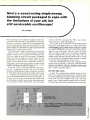
F
Digitol
OTOTYPING
System
REMEMBER THE LAST CIRCUIT THAT YOU BUILT ON A SOLDER -
less breadboard? The wires were running off the block everywhere, and were connected to a makeshift power supply. A
quick :wist of the wires, insulated by precisely angled bends,
is all that was needed so that the bare conductors never
touched, but somehow did! Once the power supply is deemed
reliable, it is a simple matter of juggling a logic probe around
in a manner as to be most effective for debugging. All the
while keep in mind that power cord movement must be kept
to a minimum, thus preventing excessive testing and repairing of the power supply.
The Digital Prototyping System described here provides a
5 -VDC, 3- ampere regulated power supply, with an LED
current monitor. Two digital logic probes with memory are
added to prevent wire -lead clutter and to make it hard to
misplace the probes. Each probe can detect pulses as short as
40 nanosec. An adjustable clock with several divided -down
outputs is included to help streamline breadboarding time
and to eliminate wasted space on the block.
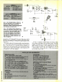
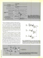
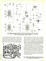
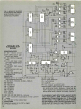
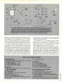
The power -supply circuit
The power- supply circuit is shown in Fig. 1. Transformer
T1, bridge- rectifier BR 1, and filter -capacitor C6 form a
full -wave power supply regulated by IC7, a 78H05 high current regulator integrated chip, and capacitor C7. The
output is rated at 5 -volts DC into a 3- ampere load maximum.
The current monitor uses a .5 -ohm, 20 -watt resistor, R26, to
cause a voltage drop equal to .5 millivolt per milliamp of
ALAN BRADFORD
The next time you undertake to design your
own digital project, let this unique device
provide you with regulated + 5- VDC power,
with LED current monitor, two logic probes,
and 12 clock frequencies from .01 to 170K Hz
P1
F1
BLACK
117-
WHITE
VAC
GREEN
S1
RL
RH
T1
11
o
O
R26
.552
20 WATT
1/2A
Mk
u
+
IN
+5
OUT
IC7
o
78H05
C6
J1
C7
COM
..:4; 4700
1000
35V
35V
J2
+5
Cl
10
35V
501- 16
RH
15
+
14
SIO1
1C2
LED1)fr
R1
R3
1MEG
1MEG
1
<<
O
O
2700
12
3
4
18
ICI
LM32
3
17
<4
16
<5
6
11
7
102
V1
R5
.7, 1K
R4
1MEG
15
12
«
<<
«
11
<<
10
<1<
LM3914
BAR -DOT
DISPLAY
DRIVER
<6
14
R2
13
1MEG
8
R6
ORL
RANGE
1K
fr-
s0,13
12
-cr
11
> _>
2100
O
1500
O
900
LM3914
MA
3000
13
cif
IN
2400
©
IC7
COM
LM78H05
LM78HV05
BOTTOM VIEW
1800
O
IC1
LM324
1200
14
O
600
300
{
*
LE010
BAR
DOT
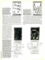
FIG. 1. THE POWER- SUPPLY PORTION of the Digital Prototyping System uses a simple bridge rectifier
to supply power to the 5 -volt DC regulator chip, IC7. Resistor R26 senses the current used at the output
and displays that miniscule voltage drop across the bar -dot display driver, IC2. With jumper JU1
installed, a bar display will indicate current
300 mA steps very much like a rising thermometer.
ii
output current. Two -ohm. 10-watt resistors were used i1
parallel to form R26. The internal current used by the 78H05
regulator, IC7, is small enough to be ignored. That proportional voltage across terminal points RH and RL is fed into
IC I , a LM324 unity -gain op amp, that ground- references the
signal so that any voltage drop on the unregulated side of the
power supply will not affect the current reading. IC2 is a
LM3914 bar -dot display driver. The input divider is calibrated to read 300 mA per LED by resistors R5 and R6. Pin 9
on IC2 selects either a bar or dot display. Connecting pin 9 to
+5 volts DC will select the bar mode.
The regulator, IC7, can put out slightly more than 3
amperes for short lengths of time. Prolonged use above 3
amperes will cause early failure of the transformer or bridge
rectifier unless they are rated well over 3 amperes. The
regulator, IC7, is internally protected against short circuits
that draw more than 5 amperes. Staying within those limits
should insure long life of the power supply.
1
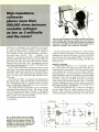
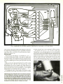
Double logic
The two logic probes are identical and are shown in Fig. 2.
Half of 1C3 and IC4 make up each probe. The operation of
only one probe will be described here. The other probe works
10
.
-
ML
the same way, and is totally independent of the first. The
numbers shown in parenthesis are symbol and pin designations for the second probe.
NPN transistors 2N3904, Q1 and Q3, along with two
sections of hex inverter 74LS04, make up the state detector
for the logic probe. Transistor Q3 turns on during low pulses
causing IC4 -b to go high and turning on the Low LED
indicator, LED13. When the input of Q3 is high or floating,
the input of IC4-b is pulled high by resistor R13 and holding
the Low LED off.
The high-detection circuit is much the same. The input of
IC4 -a is held low through resistor RI 1 whenever the base of
QI is low or floating. When a high is applied to the probe's
input, Q1 turns on pulling up the input of IC4 -a and turning
on HIGH LED, LED 1 I .
Short-pulse detection and memory are provided by 1C3 -a,
a 74LS 123 one -shot chip. IC3 -a is triggered by a high to low
transition of IC4 -b or a low to high transition of IC4 -a. The Q
output remains low for a time determined by resistor R19 and
capacitor C2, past the last trigger pulse. The pulse time is
approximately 250 msec. with the values given for R49 and
C2. Pulse memory is accomplished by closing PULSE switch,
S2. The low pulse from the is brought to the junction of C2
LED 11LED 15
S3
S2
LED 1LED 10
El
CLOCK
OUTPUTS
LED10
THE DIGITAL PROTOTYPING SYSTEM is as rich looking as its name sounds. Light- emitting diodes LED1 through
indicate current supplied to an external- connected project in steps of 300 milliamperes. Clock outputs offer six frequencies
from 170 kHz to 10 Hz at high setting of FREQ ADJ potentiometer R24 at maximum and 1560 to .01 Hz. (approximately 5.7
pulses per minute) at the minimum setting. Two independent and separate pulse -probe circuits are provided with suitable
high- and low -state indicaters with pulse memory. Of course, there's the 5 -volt regulated power supply terminals and POWER
System.
ON /OFF switch S1 -the brutish, but ever so essential, purpose of the Digital Prototyping
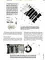
FIG. 2. THE LOGIC AND CLOCK PORTION of the Digital Prototyping System could be separate projects
by themselves. The clock section offers six time -related clock signals for intervals listed in Table 1. The
logic -probe section actually consists of two identical probes. The diagram lists symbol and pin
designations for one logic probe, and another set of designations in parentheses for the second probe.
+5V
HIGH*
S02-
IN A(B)
,1/,
LV
R15
(02)
33K
B
(R14)
\AA,
/
d
1C4
N
(13)
7
R91R10)
(10)
(8)
(9)
(7)
2
[C4c
10012
74LSO4
2
1
(9)
(12)
74LSO4
1C3
R17
Wir
3.3K
C4
R21
.001
(022)
27012
16(4)
LOGIC PROBES)
CABLE
1
2
3
T
-
LED13
(LED 14)
T
3
555
TIMER
5
S037
4060
6
14- STAGE 15
1
DRIVER
<
il B
1
2
14
I
MI
4
C5
3
01
.1A
5
11
106
3
(S3)
4
S02-14(5)
IC1-1C6
i
TERMINATES AT
S01 AND FRONT PANEL
SO2 AND FRONT PANEL
S03 AND FRONT PANEL
CLOCK GENERATOR
E
C
PIN
1
C
D
E
q F
CABLE
01 -04
S02- ALOW
2N3904
(2N3906)
6
R25
S2
(12)
27012
(03
2
(LED 16 )
A7
OUTPUT
12(-16
4 .18
105
R24
(C3)
ONE
SHOT
R23
27012
7
LED 15
C2
74LS123 14
DUAL (6)
(R18)
33K
4)1
1113)
15
14
1K
C
S02-
16
t
15
6
M
33K
R13
FREQ
RANGE
503S03-
PULSE
(R20),
27012
(R8) 2N3904
(2N3906)
R11(R12)
S01-16,15,14
R19
(R16)
Q1
R7
ED II
(LED 12)
15(3)
+5V
S02-12(2)
o13(4)
+5V
O
3
TABLE 1 -CLOCK RANGES
Tap No.
High Frequency
170 kHz.
11 kHz.
1395 Hz.
174 Hz.
A
B
C
D
E
F
21 Hz.
10 Hz.
Low Frequency
1560 Hz.
100 Hz.
12 Hz.
1.5 Hz.
.19 Hz.
.01
Hz.*
65.7 pulses/min
and R19 preventing the capacitor from charging and holding
the one -shot in its triggered state, with PULSE LED, LED15
on. Opening S2 causes C2 to charge and after 250 msec. Q
goes high and the PULSE indicator, LED15 goes out.
Tick tock
The clock circuit is made up of IC5 and IC6. See Fig. 2.
IC5 is a 555 timer connected in its astable mode. The frequency is adjustable by range potentiometer R24. The output
of the timer is fed to IC6, a 4060 CMOS 14-stage binary
divider chip. The input signal is divided down and tapped off
at five different stages. That allows the clock output to be
available at six different frequencies simultaneously. The
available range is from + 170 kHz to less than .1 Hertz. The
clock ranges are listed in Table 1.
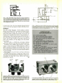
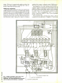
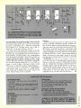
Construction
The main circuit can be assembled using an etched printed circuit board, or a wire- wrapping technique on a perf- board.
A foil pattern of the wiring side of the PC board is shown in
Fig. 3. Component placement is shown in Fig. 4.
Mount all PC components to the board, making sure of
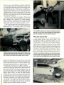
JUST SITTING THERE doing nothing makes the circuit board
section of this project seem simple. Nevertheless, it would b:
wise to resort to a printed- circuit board for construction inst?ad
of using point -to -point wiring.
proper orientation of the IC sockets, and capacitors. Make
sure that all wire jumpers are installed.
Due to the wide variety of component sizes available, the
power supply is mounted on a terminal strip as shown in Fig.
5. Capacitor C6 is not a critical value; the bigger, the better.
Any value from 3,000 to 10,000 µF at 35 volts will do the
job. If other than the specified transformer and bridge rectifier are used, make sure they can handle the current. If the
value of C6 is above 5,000 ¡4F then the bridge should be rated
at least 5 amperes. Otherwise, the high inrush of current
during power -up could cause early failure of the rectifier
The 78H05 regulator, IC7, must be mounted on a finned
heat sink, as it will he dissipating around 25 watts at 3
FIG. 3. HERE IS THE ART for the foil side of the printed- circuit board. The use of the PC board is the only sure way
to go.
o
0-0
ti]
00 00
0
a
f
DPá'1
WIRING SIDE
I
0
0
0
0
0
o
FIG. 4. PARTS LOCATED on the PC
board are shown along with wire jumpers and the bar -dot jumper JUl. With
JUl connected, the light- emitting diodes
will remain illuminated for a bar display.
The foil pattern is shown in an x -ray
view.
A grounded three -wire electrical
cord with molded plastic plug Pl is
necessary to insure personal safety. The
ground should be bonded, (good electrical contact) to the chassis with a nut, lock washer, and bolt.
The transformer or terminal strip mounting bolt is a good
place for the ground. The power- supply ground return should
also be connected to the chassis at the same point.
All the front -panel parts are connected to the PC board by
DIP jumper cables. The wires are soldered to the front panel
parts and the PC -board ends plug into 16 -pin IC sockets.
amperes output. Use heat -sink compound when mounting
the regulator to the heat sink. If the heat sink is mounted
inside the chassis, then adequate ventilation must be provided. The case of the regulator is ground so it is safe to
mount it to the back of the chassis where the cooling will be
the best.
Measure the four 1,000,000 -ohm resistors, R1-R4 with an
ohmmeter. Use the one with the highest value for R4 for best
circuit operation. Measure the output of the op amp, IC1,
with no load on the power supply. The offset should be less
than 11 mV. Some experimentation with the value of R4 may
be necessary. It must be higher than R1 to ensure a low
enough offset.
Calibration and checkout
The only adjustment is for the current monitor. The voltage at pin 6, IC2 should be set equal to the voltage at pin 5
during full rated output (3 A). A simple calibration load is
shown in Fig. 6. Connect a DC ammeter, capable of display-
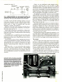
FIG. 5. PICTORIAL DIAGRAM FOR THE POWER SUPPLY wired to a terminal strip in the device's metal box enclosure. Be sure to space
NOTE:
MAKE SURE
R26 HAS ROOM
FOR HEAD DISSIPATION
R26 CONSISTS OF
TWO RESISTORS
parts so that a flow of circulating air will cool
those that tend to heat up.
C6
GROUND
TO PC BOARD
&FRONT PANEL
GROUND
TO
REGULATOR
CONNECT
TO CHASSIS
GROUND
RH TO
RL TO
PC
BOARD
+DC TO
PC
PC BOARD
& FRONT PANEL
REGULATOR
+5 VOLTS
FROM
REGULATOR
BOARD
+5 VOLTS
TO
12.6V AC
FROM
TRANSFORMER
Ti
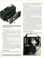
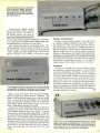
A PEEK AT THE BACK of the unit
shows the 5 -volt regulator chip
mounted on an over -sized heat sink
which is OK considering that the
heat sink was taken from the junkbox. Fuse location is satisfactory
and strain relief on the power corn is
very good construction practice.
F1
STRAIN
RELIEF
GROMMET
ing 3 amperes, in series with the calibration load as shown.
Adjust R, until the meter reads 3 amperes. Using a DC
voltmeter, measure the voltage at IC2, pin 5. Record the
voltage and disconnect the load. Now move the voltmeter to
pin 6 and adjust R6 until the voltage reading is the same as at
pin 5. All voltage measurements are taken with reference to
ground.
Be cautious around Q, (Fig. 6) as it is dissipating 15 watts
and will get very hot without a beat sink. Severe burns could
result if the transistor is touched. If not using a heat sink, then
disconnect the positive lead that goes to the power supply
every 15 seconds to allow the transistor to cool to a safe
temperature.
The checkout of the logic probes is simple. With the power
supply turned on, touch one probe to the + 5 terminal. The
HIGH LED (LED 11) should go on and the PULSE LED
(LED15) should stay on for only about 250 msec. Touching
the probe to ground should light the Low LED (LED13) and
the PULSE LED should flash when the probe is removed from
ground. With the memory switch, S2, on, touch the +5 bus
and then ground the probe. The pulse LED should go on and
stay on even after the probe is removed from the signal.
When the switch is turned off the PULSE LED (LED 15) should
extinguish about 250 microseconds later. Both probes work
PARTS LIST FOR DIGITAL PROTOTYPING SYSTEM
SEMICONDUCTORS
IC1 -LM324 operational amplifier (op -amp) integrated
circuit
IC2- LM3914 bar -dot display driver integrated circuit
IC3- 74LS123 dual one -shot integrated circuit
IC4- 74LSO4 hex inverter integrated circuit
IC5 -LM555 timer integrated circuit
IC6 -4060 CMOS 14- stage driver integrated circuit
IC7-78H05 5 -volt DC regulator integrated circuit
BR1
-A, 50 -Ply bridge rectifier module (Radio Shack
273 -1180 or equivalent)
LED -LED 16 -Light emitting diode, red, 20 mA forward
current
01, Q2- 2N3904 NPN transistor
03, Q4- 2N3906 PNP transistor
RESISTORS
All resistors are 1/4-watt, 5% unless otherwise specified
R -R4-1- Megohm
35 -WVDC electrolytic
35 -WVDC electrolytic
ADDITIONAL PARTS AND MATERIALS
E1- 6- terminal, barrier -type, screw -mount strip
Fl -',/2-A fuse and holder
R15 -R18. R21-
-Neon panel indicator light with built-in dropping resistor
J1, J2 -Quick connect'disconnect, color -coded binding
terminals (type used for rapid connect to speaker leads)
J3. J4 -Multi -way binding posts, black
S1 -DPST power switch
S2 -S3 -SPST miniature toggle switch
T1 -Low- voltage power transformer; 117 -VAC primary
winding; 12 6 -VAC. 3A secondary winding with no center tap
3- Cables, ribbon -type with 16 leads, terminal one end in
16 -pin DIP jack to mate with 1E -pin DIP IC -type socket
1- Heatsink for I07. 50 -watts dissipation minimum
(Radio Shack 276 -1361)
Printed -ci -cuit fabrication materials, mounting hardware, knob, case, heatsink compound, terminal strip,
solder, wire, line cord with moulded 3 -prong AC plug
(P1). etc.
R26-0.5 -ohm, 20 -watt (use two 1 -ohm, 10 -watt resistors in parallel)
CAPACITORS
10 -µF, 35 -WVDC electrolytic
C2, C3- .47 -11F disk
C4- .001 -µF disk
C5- .01 -µF disk
An etched and drilled printed- circuit board is available from Micro Power Systems, RFD *2, Rt. 4 -A,
Enfield, NH 03748. Price is $11.50 and includes shipping and handling charges. Please note: All boards
shipped UPS unless otherwise specified. Visa and
MasterCard accepted. Be sure to give all information on card.
-6
1
1
R5, R13.
R14- 1000 -ohm
R6- 1000 -ohm
trimmer potentiometer
R7, R8, R19, R20- 33.00 -ohm
R11, R12- 100 -ohm, 1/2 -watt
R23- 270-ohm
R24- 500,000 -ohm potentiometer
R25-3,300 -ohm
Cl-
14
C6- 4700 µF,
C7-1000 -µF,
11
VENTED
CABINET
PRINTED
CIRCUIT
BOARD
3
RIBBON
CABLES
FRONT
PANEL
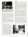
DROP THE FRONT PANEL and the
interior looks like a well-designed
project with good construction practice. Ribbon cables are used to interconnect components on the front
panel with the printed- circuit board.
Thus, in the event that faulty wiring
occurs in construction, it can be
quickly traced by using the cable's
color code. The printed- circuit board
is held in place by holders specially
designed for that purpose. However,
you may want to go the less expensive route by using low -cost
standoff posts which do the same
job at a fration of the cost.
in the same manner and can only be used for TTL and positive
CMOS circuits.
The clock frequency is adjusted by potentiometer R24. By
selecting a range tap and changing the setting of R24, any
desired frequency can be obtained within the range selected.
The outputs B through F are CMOS outputs with a 5 -volt
swing. External buffering may be necessary for some circuits. The 4060 CMOS divider chip, IC6, has a fan out of 2
74LS loads, and cannot drive 7400 TTL devices directly.
The Digital Prototyping System should give you everything you need to easily design many more projects in the
future. Debugging is also a snap due to the elimination of all
the extra leads and wires that normally clutter up a breadboard.
SP
WITH THE FRONT PANEL completely removed and the printed circuit board slid out of its holders, the project looks very much
like a simple power supplywhici it really is! The add -on circuits make the unit extremely valuable to the circuit designer and
proto-yper, who must monitor Vc,
current and have knowledge of
the switching action in the
externally -powered circuit.
C
RX
Oc
1K
253055
E
BOTTOM VIEW
for the Digital
Prototyping System. Make brief current tests of 15 seconds or
less; otherwise, the transistor will overheat. Even a brief test will
raise the transistor case temperature sufficient to burn flesh.
FIG. 6. HERE'S A SIMPLE CALIBRATION LOAD
.
+,t.r g4r
ivr:3. .G.s34 -.,+.y.
:.Cr.'a tr.s<@ v3:
1111
Liúii.:>r. íísS`'i
Elecironi
G
ic
.11.251k147..
1!;;
COMpL
--- COMPLETE
ado
side .SW
$ tE"-;e-by-step TV IF o:iga:
TIME
FERST
the
for
BUILD YOUR OWN ROBOT!
Send today for your 52 -page (81/2 x
11 ") booklet containing complete reprints of all eleven articles in the
Build Your Own Robot series by Jim
Gupton.
This all- inclusive reprint gives you all
the data you need to build your own
Robot.
TELLS EVERYTHING YOU NEED
KNOW to build the Unicorn -1
Robot without the need for an engineering degree or special equipment.
TO
Radio-
Electronics
The robot is fully mobile with minipulator arms to grasp, lift and carry.
MANIPULATOR ARMS and end -
effectors (hands) are what enable the
robot to perform useful tasks. Details
of construction techniques and considerations are fully explored.
MOBILITY BASE is not a lunar
space station. It is the drive system
that permits the robot to move from
here to there. Full construction details along with a discussion of power
sources is included.
Robot Reprints
200 Park Ave. South
New York, N.Y. 10003
want to order
reprints @$12.00 plus $1.00
postage and handling for U.S., Canada and Mexico.
Add 96¢ sales tax for New York State residents only.
U.S. Funds only.
I want to order
reprints @$12.00 plus $3.00
Air Postage and handling for all other countries.
U.S. Funds only.
THE BODY -FRAME AND ROTATION MECHANISM. This is the part
that makes Unicorn -1 look like a robot. Wood and Formica are the materials for the body. Motors and gears
are what make it function.
COMMUNICATIONS. How you can
tell your robot what to do. Preprogramming techniques....radio control
....computer control are all detailed.
SENSORS. How to add sensors so
your robot doesn't bump into things.
SP4
Please print
I
(Name)
(Street address)
(city)
Allow 6-8 weeks for delivery.
(State)
We do not bill, check must be enclosed.
(ZIP'
If you like to make things work. .. and
then find out why they work-
you could bbe getting paid
for doing something yyou
r
Learn electronics...ri g ht on up to an
Associate Degree...in your own home
without giving up your present job
or income.
,
r
People who really like their work get ahead
faster. And, when your natural abilities
match the job requirements, you have an
extra advantage. When you use
practical training to sharpen your
skills, your odds are better for
keeping your job even if others
are losing theirs. So, if you find
satisfaction and interest in
making things work, a career
in electronics may be for you.
WHY ELECTRONICS
IN THE 80's
Opportunity.
The field of electronics simply offers more
and more job secareer opportunities
than most other fields today. Take
curity
digital technology, for example. Much of the
new telecommunications, data processing,
and production equipment depends upon
sophisticated microprocessors to receive,
sort, and send digital signals in microseconds. Two of CIE's newest home study
courses combine digital electronics theory
with actual experience on digital equipment.
Successful completion of either one of those
courses is creditable toward CIE's Associate
Degree program. That's right...you can earn
an Associate Degree without attending a
-
-
single class session.
MAKING THINGS WORK
Many of CIE's Career Courses stress "hands on" training. We believe textbook knowlbut it's just as important
edge is important
to know how to apply your book learning
in practical situations. From basic circuitry
in CIE's Personal Training Laboratory in
several Career Courses, through the
Microprocessor Training Laboratory in the
Associate Degree program, CIE helps channel your desire to "make things work" into
skills you can sell.
-
enjoy!
START MAKING
THINGS WORK
FOR YOU
IN A CLASS BY
YOURSELF
One of the great benefits of home study is
the independence it gives you. You study
where and when you want to. You move as
fast as you can handle it. There's no classroom to go to because with CIE, the
classroom comes to you! But, you're never
alone. When you request help, the CIE
electronics expert best qualified will
personally respond in writing.
Send today for the CIE school
catalog and complete package of career
information. It's all FREE, and it will help
you decide where you want to start and how
far you want to go. For your convenience,
we'll try to have a school representative contact you to review the various educational
programs and assist in course selection. Just
mail the postage -paid card or write, mentioning the name and date of this magazine.
We want to help you make things work, so
send for your FREE school catalog today!
SET YOUR OWN GOALS
CIE's wide selection of courses gives you
many options. You start with a Career
Course that suits your talents. Then, since
more than half of CIE's courses include a
series of optional lessons to prepare you to
pass the government -administered FCC
License exam, you can get an FCC License
...a requirement for some electronics jobs
and a credential for all electronics jobs. You
may then go on and earn an Associate in
Applied Science Degree in Electronics
Engineering Technology. It's all up to you!
CIE
CIE's Microprocessor Training Laboratory,
an integral part of the Associate Degree
program, lets the advanced student apply
digital technology in many of the same
ways electronics professionals do.
Cleveland Institute of Electronics, Inc.
1776 East 17th Street, Cleveland, Ohio 44114
Accredited Member National Home Study Council
$OUNDBOX
80
. f,
;
'
ROBERT MURR
If your
TRS-80 game programs
are as quiet as an end-term examination,
then think what sounds like
Booiiinnnggg, Zapppp, Whizzzzz will do
to keep your play- action popping.
MANY READERS HAVE ENJOYED PLAYING GAMES ON THE TRS -80
Model I. Yet something definitely felt missing as we brought
the alien within our sights, pressed the fire button, and
simply saw the word "bang' on our screen. Now with a little
hardware and some programming practice we can make these
games come to life with sound from Soundbox -80.
Though the integrated circuit behind all that has been
around a while, and has been used in other computers, it has
not been interfaced specifically to the TRS -80. In this article,
I will discuss such an interface circuit, how it works, how to
use it, and how to build your Soundbox -80.
"
TABLE
BDIR
o
o
1
PSG (IC1) ENABLE LOGIC
BC2
BC1
o
1
0
1
PSG (IC1)
FUNCTION
Inactive
Read from PSG
Write to PSG
Latch address
The circuit
Programmable sound generator (PSG) chip ICI , the AY3 -8910 by General Instruments, is designed to send and
receive data over the eight -data lines. That data is transmitted
between the chip's set of 16 registers, which are used to
select the desired sound, and the computer's bidirectional
data bus. The circuit of Fig. includes a 74LS245 octal,
tri -state bus transceiver integrated circuit, IC2, which serves
that purpose.
The majority of the Soundbox -80 circuit in Fig. is used
for address decoding and chip- enable logic. For the tri-state
buffer, IC2, there are two controls: enable (IN), pin 19; and
direction (DIR), pin 1. The enable control signal must pulse
low during any transaction between the computer and the
sound circuit; otherwise, the outputs are tri- stated in both
directions. The direction -control signal, pin 1, simply decides whether the data will be shipped from Soundbox -80 to
the computer, or vice -versa. The enable logic for the ÁY -38910, ICI , must also be carefully planned. The requirements
1
1
+5V
IC6-a
J1
Ii
-1A7
2F
38
oi
35 01
31011
34 GI
40 01
1
I
12
2
11
A6
6
A5
5
A4
4
A3
3
A2
2
40
ICI
AY 38910
IC3
I
Al
27 o1
C6-b
1
3
IC5
a
X}
OUT 127
's
25 DI
801
AO
GND
OUT 126
_L
4
11
TO REG.
IC5
12
oJ
19
0]
5 -VDC
POWER
12
OUT
IN 126
5)IC4h
SUPPLY
(SEE FIG. 2)
J1
IC5c
1
DO
9
RESET
2 0i
28
BC2
10 32
0 26
o
o
J
lo 22
+5V
+5V
23
RESET
1018
27
25
29
BDIR
A8
10 28
Io 24
t0 20
BC1
19
A
3
38
IC1
PROGRAMMABLE SOUND
GENERATOR
AY- 3.8910
'r
A9
TO
AUDIO AMP
(SEE FIG.3)
241
- -,
1030
CLK
22
D7.DO
30
FROM
CLOCK
D7
CIRCUITRY
1C2
(SEE FIG. 4)
OCTAL BUS
TRANSCEIVERS
74LS245
D0-4->D7
DIR
37
D71..__
2111
DO
9
2
1
DATA BUS (DO, D1, 02, D3, D4, 05, D6, D7)
IC3- 74LS30
IC4
IC5 IC6 IC9 IC10
NRjÚ
74LS32
741502
74LSO4
4011
4013
40
IC8
U
LM386
IC1
AY-3-8910
1C2
74LS245
1- SCHEMATIC DIAGRAM FOR THE PROGRAMMABLE SOUND GENERATOR section of Soundbox -80-the
noisy addition to your TRS-80. The text takes you by the hand through the schematic diagram which, in effect, is a
basic course in logic theory. The associated power- supply circuit, audio circuit, and clock circuit are provided in
the following figures-all of which are part of Soundbox -80.
FIG.
are summarized in Table 1. The BDIR signal, pin 2, must go
low whenever writing or latching to the internal programmable sound generator, IC 1. Since the BC2 input (pin 28)
does not need to be used, it is tied to the + 5 -volt supply. The
BC1 signal, pin 29, only goes high during the read and latch
operations.
The logic to create those enable functions begins with the
address decoder, made of IC3 and IC6 -a, which is an inverter
used to select the desired port. It can be replaced by any
combination of inverters on the address lines A2 through A7.
The ouput of IC3 goes logic low whenever the lowest 8 bits of
the address buss are decimal 126 or 127. That output is
combined separately with the inverted and non -inverted AO.
The lowest address line is used to select whether the operation is latching to or writing to the chip. IC5 -a, b, and c are
used so that the circuit will only respond during an input or
output instruction. They are again combined and are used to
feed the master enable of IC2.
Soundbox -80 needs only a regulated 5 -volt power supply
(you cannot power it from the 5 -volt pin on the TRS -80 edge
connector) a clock, and an audio amplifier. Schematic diagrams for each of them are illustrated in Fig.2, 3 and 4. The
through 4)
schematic diagrams for Soundbox -80 (Figs.
may be built on a circuit board or wire -wrapped. The connections to the TRS -80 are made via a 40 -pin, card -edge
connector JI.
The power supply of Fig. 2 uses a 6.3 -VAC transformer, a
full -wave bridge rectifier, and a 7805 five -volt regulator
chip. The 2200 µF electrolytic capacitor is used to filter the
DC before the input of the regulator; and the 0.1 µF capacitor
used to reduce the noise on the 5 -volt output. Additional 0.1
disk capacitors may be tied directly across the Vcc and
1
117
TABLE 2
VAC
OUTPUT TO THE PSG (IC1)
0 OUT 126,5
20 OUT 127,20
30 OUT 127,30
Ti
;Latch register 5
;Load register 5 with 20
;Load register 5 with 30
V
1/4 A
J2
S1
TABLE 3
o
y,
+5v
INPUT FROM THE PSG (IC1)
10 OUT 126,5
20 X = INP(126)
30 PRINT X
;Latch register 5
;Load X with contents of
;register 5
;Print contents of register 5
TO FIGS,
1,3AND4
D1-04
1N4004
FIG. 2 -THE POWER- SUPPLY CIRCUIT is
the usual regulated 5 -volt DC supply that
powers so many projects built by ex-
I-.
perimenters. Plug P1 and jack J2 should be
polarized to avoid accidental voltage reversal. Otherwise, poof go the IC's.
5V
AUDIO
FIG. 3 -THE AUDIO -OUTPUT CIRCUIT pro-
duces up to one -watt of audio power. That
üs too much for the small speaker built into
Soundbox -80. Keep the volume setting
down to avoid damage to the speaker. If
you wish, the LM386 can power a heavy duty speaker externally connected, or, to
spare the ears of those around you, connect a headphone.
FROM
1C1
PINS 3, 4, 38
(SEE FIG. 1)
C3
R1
10µF
10K
+IE
VOLUME
R4
10K
vvs,
R3
loQ
1T
C5
1
C7
4741-F
0.1,,F
I
ground pins of ICI through IC10 circuits if the noise is still a
problem and can be heard on the output of the audio amplifier, pin 5 of IC8 (Fig. 3). The power supply plugs into the
unit via J1.
The audio output of the programmable sound generator,
ICI , can be used to feed an external amplifier or the circuit of
Fig. 3 may be used as a one -watt internal amplifier for
Soundbox -80. The potentiometer, R4, is used as the volume
control and the output of the LM386 is fed through the 470
/.1.F capacitor to an 8 -ohm speaker.
SPKR
8S2
In Fig. 4 a standard 3.579545 MHz color -burst crystal
X 1, is used as the basis of the oscillator circuit. The 4011
CMOS NAND gates IC9. are used to develop the 3.579545
MHz frequency and IC 10, a 4013 CMOS dual D flip -flop..
IC10, is used to divide the clock frequency by two to
1.7897725 MHz. That is within the -2 MHz range required
by the PSG circuit in IC1.
1
PARTS LIST FOR SOUNDBOX -80
SEMICONDUCTORS
D1 -D4-1 N4004 silicon rectifier diode
ICI-Programmable sound generator large -scale integrated circuit made by General Instrument
lC2- 75LS245 octal bus transceivers with 3 -state outputs integrated circuit
IC3- 74LS30 8 -input NAND gate integrated circuit
IC4- 74LS32 quad 2 -input OR gate integrated circuit
IC5- 74LS02 quad 2 -input NOR gate integrated circuit
IC6- 74LSO4 hex inverter integrated circuit
IC7 -7805T + 5-volt regulator integrated circuit
IC8 -LM386 power audio amplifier integrated circuit
IC9 -4011 quad CMOS NAND gate integrated circuit
IC10-4013 dual CMOS o flip -flop integrated circuit
RESISTORS
All resistors are 4 -watt, 5% fixed units unless otherwise
specified
R1-10,000-ohm
R2, R3
-10 -ohm
R4- 10,000 -ohm
R5 -10- megohm
R6-300 -ohm
22
potentiometer, PC -board mount
CAPACITORS
2200 -11F, 15 -WVDC electrolytic
C2, C4, C5- .1 -µF, 15 -WVDC Mylar
C3- 10 -p,F, 15 -WVDC, electrolytic
C6, C7-470 -p,F, 15 -WVDC, electrolytic
C8-20 -pf, 10 -WVDC, ceramic
Cl-
ADDITIONAL PARTS AND MATERIALS
F1
-1/4-A fuse
J1-40 -pin
card -edge cornector
J2- Two -circuit polarizedack to connect 5 -volt supply:
any type acceptable
polarized plug to mate with J2
S1 -SPST toggle or slide switch
T1 -Power transformer; 400 mA or better 6.3- to -12.6VAC secondary winding
X1- 3.579545 MHz TV crystal; or similar type rated at
2 -4 MHz
SPKR
-10-ohm speaker, 2- 2V2 -in. diameter
1 40-pin DIP socket, 1 20 -pin DIP socket, 6 14 -pin DIP
socket
1 8 -pin DIP socket, plastic box, cement, wire, hardware,
solder, etc.
P1-Two -circuit
-8
THE SOUNDBOX -80 looks like a haven
C8
for roosting integrated circuit chips.
Sockets are used to mount the IC's.
Make up your mind before you purchase the sockets as to the technique
for wiring the unit. Wire -wrapping is
best and calls for special sockets. If
you prefer to interconnect and solder,
wire -wrap sockets with their long
posts may still be a good idea -you
could always snip off the excess
lengths after the unit is wired. The
plastic box is a garden- variety that's
available almost everywhere. You may
prefer a sturdier plastic box that most
experimenters can buy at local electronics parts stores.
3.579545 MHz
J1
SEE
X1
FIG.
fn
1C8
120pF
W.
R5
10M
1
CLOCK
OUT
R6
30052
8
5
IC9 d
1/44011
10
105
+5V
IC2
12
11
DUAL
D FLIP-FLOP
4013
9
1
4,6,71
8,101
5L_ _J2
4- HERE'S A HANDY CLOCK CIRCUIT that fills the bill for
Soundbox-80 and just about any TTL and CMOS circuit requiring
clock pulses in the megaHertz's. Since the 4013 is a dual integrated circuit unit, you may want to divide again to reduce the
output clock pulse to one half.
FIG.
1010
More information on the operation of the programmable
sound generator is available in the AY -3 -8910 data manual,
as well as a more detailed explanation of the logic required.
The circuit may be built on a circuit board or wire -wrapped.
Using Soundbox -80
The programmable sound generator, ICI, can be easily
accessed from a BASIC program. The sequence for shipping
data to one of the chip's registers is show in Table 2. Note
that each time the data is to be transferred to or from a
J1
different register than the time before, the new register number must first be latched. The sequence for reading information is shown in Table 3. A wide variety of sounds can be
generated using that chip. The PSG can produce sounds
ranging from explosions and laser fire to music with three part harmony. The only way to get really familiar with it is
through trial and error and the manufacturer's data manual.
The circuit can be built with relatively little cost or know how. It will provide a new dimension for your TRS -80 and
much entertainment for you. Now you can look toward a
happy BOING, ZAAAAAAAP and PINGGG!
SP
J2
SPKR
BELLY -UP VIEW of Soundbox -80 illustrates the rat's nest wiring that makes the
programmable -sound generator circuit do its thing. Jack J2 is for connection to the
external power supply. You may want to add a closed- circuit jack to hook-up an external
loud speaker. If you prefer to connect a stereo headphone, use a closed- circuit stereo jack
and connect both channels to the audio output so that both ear pieces produce sound.
c USTOM
SOUND
F 0 R YOUR CAR
LARRY GLENN
"IRON"
well beyond what you can afford, you don't have to wait for
new "wheels" before you upgrade your car radio to stereo,
or even to real high- fidelity status. Then again, maybe you
had a tape player in the dash that some hoodlum ripped out,
leaving a large gaping hole. Either way, you can add or
retrofit one of the new hi -fi or super -fi AM /FM- stereo,
cassette -tape radios in just a couple of hours. What you save
on installation can pay for a pair of super -duper multi-way
speakers, or half the cost of the radio itself.
The speakers themselves are no problem. Virtually every
modern dash is pre -moulded for miniature stereo speakers. If
you like something other than a thin, tinny sound-which is
what you'll get from mini -size dashboard speakers -you'll
find that in most instances the rear deck has been precut for
larger speakers of the 5 x 7 -inch or 6 x 9 -inch variety, or
for some other size that will sound better than the itty -bitty
speakers generally used in the dash.
Usually, all you have to do is fit the speakers to the existing
cutouts and run the wiring to the radio location, leaving a
couple of feet of slack that can be folded behind the dash and
taped in place.
The real nitty -gritty of the installation will be fitting the
WHILE DETROIT AND TOKYO MIGHT HAVE PRICED THEIR
YOU GET JUST ENOUGH harJware with a modern
"universal"
aftermarket radio to install it; possibly, a full -length wiring harness with the more expensive radios. This harness has the
speaker terminals and speaker /power connector pre- attached.
24
radio, because so- called "universal" radios really aren't
universal; they are anything but...! The photographs show
the highlights of an in -dash radio installation.
Universal what?
Before we proceed, let's straighten out the word "univer-
sal," because most of the car radios are sold as either
a
universal or DIN type. DIN simply means it will fit directly
into the dash of European cars. Europe has a standard for
virtually everything. It might also mean the radio of your
choice won't fit at all. It appears that given any two measurements, the Europeans will use the most difficult and expensive size as a standard. On the other hand, the term
universal generally means; the distance between the two sets
of controls (volume, tone, tuning, etc.) can be adjusted.
Nothing else other than the shafts are guaranteed to fit into
your car's mounting holes.
The term universal came about this way. Up until a few
years ago aftermarket radios generally were packaged with
an assortment of hardware and front -panel accessories
specifically matched to a particular car. At worst, the installer could use some of the supplied panel accessories, such
as filler panels, to make it appear the radio was factory
PENCIL POINTS TO the clamp and chassis holes that permit the
control -shaft spacing to be easily and rapidly adjusted for your
particular dashboard. Clamp should not be discarded. It is the
only truly "universal" part of a "universal" radio.
If you can buy it
you can install it!
Shopping wise and
installing it yourself
may cut the radio's
final cost in half!
0111
1I11,kmllNplle
11111
!11111111
II III
lil III
I
..
Courtesy of Cadillac Cimarron '83
equipment. Also, some cars, such as those from Chrysler,
require a special mounting bracket if the car wasn't sold with
a radio. Usually, the special bracket was available from the
same people that made the radio. In a sense, the aftermarket
radios were truly universal because they came with mounting
and trim hardware. At the very worst, the installer might
have to purchase a special mounting bracket.
Today, you get none of the special hardware with a universal radio. The average person can't even get the mounting
bracket if it's needed because most stores that sell this item
are only "wholesale" or "for the trade." If you're stuck for
a bracket or trim panel, try a junk yard. Generally, they'll let
you have either for a couple of dollars, which is a lot less than
you would pay a dealer for the item. For example, the final
trim panel shown in the photographs was obtained for $1
from a local "junkie." In some junk yards you have to do the
stripping, so bring your tools.
What you get
OK! Let's get on with an installation. When you open the
radio you'll find it's packaged with assorted mounting nuts,
perhaps a few screws, knobs, a strong metal strap, a trim
panel, possibly some electrican's "wire nuts" for splices,
HERE IS THE ONLY metal part of an electrical Quick- connect. It
taps viring without actually cutting through the copper wires.
Wires are placed in "tunnels" or grooves, plastic hinge placed
over -hem, and gently squeezed by pliers to make connection.
and possibly some wires attached to a connector that provides
the speaker and power connections, or a separate wire might
be used for the power.
Depending on the price of the radio, or how greedy the
manufacturer wants to be, the connector(s) might be attached
to little stubs of wire which must be spliced into your existing
wiring (or wiring you install), or the connectors might be
attached to a wiring harness that will stretch from the rear
deck speakers to the dash with a few feet left over to spare.
A really decent harness will also have push -on connectors
for the speaker so you don't have to lie flat on your back in the
car's trunk trying to solder wires on the speaker terminals.
The harness will also be color -coded so you get the speaker
phasing correct the first time. Regardless whether you're
using a harness supplied with the radio or one you have made
yourself, run the wires up to the radio's location before you
install the radio. There probably won't be room for your
hands behind the dash after the radio is installed.
If the kit is provided with wire nuts, don't use them for any
connections already in the vehicle, such as existing speaker
wires, the power wire, etc. To use the wire nuts you must cut
and strip the existing wires. This has produced many
heartaches for installers who found the wires were too short,
FOLD THE PLASTIC HINGE over and squeeze the Quick- connect
with pliers to drive the metal gizmo through the wires' insulation.
Since everything is encased in plastic you can make the power
connection while power is on (if necessary), but don't do it!
simmismidortAll
25
THE CIGARETTE LIGHTER power wire or the vehicle's original
radio power wire is a good place to splice in radio's power wire.
Should you make a mistake, Quick- connect comes apart easilytape the original wire where the gizmo cut through the insulation.
too fragile, or whatever. A more secure and easy -to-use
connector is something called a "Quick- connect," or
"Scotch -lok," the plastic device shown in the photos. The
beauty of the Quick- connect is that it's fully insulated, and
you can make a splice with power on the circuit. The device
is a sort of plastic dual tunnel with a small metal gizmo in the
center and a hinged plastic cover. You place the wire to be
tapped in one tunnel, insert the connecting wire in the other
tunnel, fold the plastic cover and squeeze with pliers, thereby
driving the metal gizmo into the pair of wires where it pierces
the insulation when making the connection without cutting
the wires. This device works best on stranded wire. Solid
wire gets nicked and breaks easily.
If you need to tap the vehicle's wiring for radio power use
the original power wire for the factory radio; or the wire
meant for the cigarette lighter. It often can be pulled directly
off the back of the lighter assembly, and since it usually gets
turned off by the ignition lock, it's a good power source for
the radio.
How to do it
Before starting the actual installation of the radio, adjust
the spacing of the control shafts. Measure the separation of
the shaft or control holes on your dash, then loosen the nuts
GET AN ORIGINAL -EQUIPMENT trimplate from your local junk
yard and cement it to the dash if necessary. Fill in any open
spaces in the new trimplate with strips of scrap rubber or new
shoe leather. Cement these strips to the trimplate.
26
THE PERFORATED STRAP supplied with the radio provides both
rear support and the grouid connection for the radio. Bend it to
the required shape before you install the radio. If possible, also
get one end secured before tFe new radio is slid into position
.
on the shafts enough so their locking clamps can be slipped
out of their holes, set the shafts to the correct spacing, and
then rotate the clamps so they easily fall into a hole drilled in
the chassis around the shaft Then tighten the shaft nuts. Do
not discard the clamps and try to hold the shafts in place with
just the nuts
won't work. You'll either snap the nuts or a
shaft(s), or the shafts will work loose in a few days. The
clamps must be used. If they don't easily fit in a hole try a
different orientation for the clamps; at some point they will
drop directly into a matching hole.
-it
Strap
it
Next, locate the metal strap with the holes that was supplied with the radio. The instruction manual that came with
the radio probably shows the strap hanging from some part of
the dash to a screw on the back of the radio, thereby supporting the radio. The radio does need support if it has a tape
player because tape radios are relatively large; they place a
lot of strain on the dash if all that holds the thing in place are a
couple of nuts on the front panel. Unfortunately, most modern cars don't have any place to which you can attach the
strap as shown in the radio's manual. The "hanging strap"
might have been possible five to twenty years ago, but the
modern dash probably is plasic, is molded, and has no room
USING AN INSULATED A_IGNMENT SCREWDRIVER adjust the
AM "trimmer" for maximum sensitivity to "high end" AM stations. Set the radio's dial to a Neak station near 1400 kHz on the
dial, raise the car antenna, and tune for maximum volume.
USE A DEEPWELL SOCKET WRENCH to tighten the nuts on the
WHAT'S THIS!!! The trimplate doesn't fit! Correct! The days are
long past when a universal trimplate that actually fits all cars is
supplied with a universal radio. You will have to do considerable
material fabrication to make a new trimplate fit the old gap.
for your hands, a tool, or even a screw for the strap.
In some vehicles the strap can be routed under the radio to
a metal support plate for the dash, or the reinforcement for
the ash tray. Whatever, simply bend the strap so it comes
from under the radio. The strap is iron and not the easiest
thing to bend-that's why it makes a good bracket. Use a vise
to hold the strap and hammer it to shape.
Try to get the strap in place before installing the radio
might not be possible later. Either attach the strap to the
radio, saving the support connection for last, or vice versa.
Then install the radio in the dash, using a deepwell socket
wrench to secure the shaft nuts. Don't try to force a standard
socket wrench on the shaft-it's not deep enough -and don't
use pliers; that will just chew up the controls. You have most
likely spent at least $100 on the car radio, possibly $200 or
$300; spend a few dollars for a deepwell socket wrench and
do the job the right way. By the way, don't try to use
long -nose pliers for the shaft nuts. You'll probably ruin the
pliers, and they cost more than deepwell socket wrenches.
In many instances you're going to find the trimplate
doesn't fit properly because there is no such thing as a
universal trimplate. Most likely, there will be holes and
openings showing around the trimplate, or it's just plain
ugly. (I think they train student designers on radio trim
accessories.) Try your local junk yard for an original equipment trimplate. Even if its cutout is somewhat oversize,
a few strips of black rubber or leather (scrap from a shoe
repair shop) cemented to the "factory" trimplate will look
like original equipment to all but the most thorough scrutiny.
If you don't have the hardware to install an original equipment trimplate use a few drops of an adhesive such as
comes in a tube and is the same stuff used to
"Barge "
cement rubber soles to shoes. It will certainly hold the trimplate.
You're almost done. Install the knobs, plug -in the speaker, power, and antenna wires, tune the radio to a weak station
near 1400 kHz, and using an insulated alignment screwdriver
adjust the "AM trimmer" for maximum signal strength. On
cassette radios the trimmer is often reached through the
cassette loading slot. On other models it is accessible through
a hole in the rear or the side of the chassis.
Finally, re- install any ash tray, glove box, or accessory
hardware you might have had to remove to get at the radio's
location. If you have tapped into the cigarette lighter's wiring
make certain you have re-connected it to the back of the
SP
lighter assembly.
FINALLY, RE- INSTALL the ash tray or glove box if they were
removed when installing the radio. Make certain you re- connect
the cigarette lighter. If your car has missing hardware and worn
parts on the dashboard, try to pick those up at the junk yard.
SNAP IN A CASSETTE when you tire of listening to the good
sound your in -dash radio is playing. If you installed an AM'FM
unit, then FM is for you when driving about town or the local
countryside. For long rides cassettes and AM listening is best.
control shafts. Pliers, wrenches, and other ill- suited tools only
cause damage to the control shafts, which aren't all that firm and
may be damaged doing a task they are not designed tc do!
-it
There's more
-it
mokc Your Own
COMPUTER
CABLE!
JOHN SMITH -RICHARDSON
Computer cables either stock items or custom design
are very expensive. Make them yourself and
experience a retail savings from 50 to 75 percent!
IT IS SAID, NOT COMPLETELY IN JEST, THAT POLAROID COULD
afford to give their cameras away, because once you own one
ycu're married to Polaroid forever. Only they make the film;
they can charge what the traffic will bear, and that's economics!
The same can be said of computer-peripheral manufacturers. There are many places to get a discount on hardware such
as modems, printers, and the other gizmos that make personal computing a pleasure, but in almost all instances the
gear comes without cables. When you ask for the cables, you
than find out why they can sell the peripherals at such
fabulous discounts -most of the profit is in the cables. For
example, an ordinary Centronics -type printer cable that you
can assemble yourself for about $18 costs between S40 and
$60 at your local computer emporium. And ordinary RS 232
extension cables for a mocem, printer, or a terminal are a
literal gold mine: a 5 -foot length with something like S:3
worth of parts sells for $4C and up, while a simple gender reverser you can throw together from some junk connectors
starts at $30.
The best way to overcome the greed of the competer
shops, and save a bundle at the same time, is to simplymaice
your own cables. Sometimes it's a snap, 10- minute ob to
assemble the equivalent of a $60 printer cable, other tines it
takes a little more effort because some of the manufacti ers
throw a "hook" into their connections to force you to my
their cables. For example, the non -standard Apple par-El.el
printer connections are legandary. The quixotic numbering
THE CONNECTORS specificall
made for ribbon cable have.
razor -sharp "insulation displacement" terminals. When the
ribbon is pushed against tie
terminals the "knives" slice
through the insulation and tie
wire makes contact with theterminal(s). No soldering of arr.
kind is required.
of Radio Shack's original printer -port connections led to
many repairs during the warranty period-and many users
believe it was innumerable freebie repairs that convinced
Radio Shack to use standard terminal numbering. Then there
was Heathkit with an RS -232 terminal #20 connection
known only to Heathkit.
But does anyone every learn? Never! The latest version of
the Osborne computer instruction manual has a completely
erronious set of parallel -printer connections; after you blow
your mind and a few days work, most users wind up spending
$40 to $60 for an "approved" cable. And let us not forget
that if you use a standard "reversed" modem cable between
an Osborne and a professional RS -232 modem the computer
will lock -up. Or how about Radio Shack's Color Computer?
The rest of the world uses a D- connector for a serial interface;
the CoCo uses a 4- terminal DIN connector.
When you come right down to it, in many instances there is
no such things as a standard cable. If one end is standard the
other probably isn't; but that's no reason why you still can't
save big bucks by making your own cables.
Most computer cables can be easily assembled from a
small assortment of parts: some ribbon cable, press -fit ribbon
connectors, multi -wire (round) cable with solder connectors,
or some combination of ribbon and solder connectors. At
most, it's simply a question of using the easiest cable and
connector for a given job.
Ribbon cable is usually preferred because the connectors
clamp on; they are not soldered. Ribbon cable consists of
may individual plastic -insulated wires moulded side -byside. It's usually available in specific wire widths, such as
20, 26, 30, 36, or 40 wires. If you need something like 38
wires you simply strip away 2 wires from a 40 -wire ribbon
cable. Ribbon cable can be either all one color with one
single wire on either side a different color, or every fifth wire
might be a different color to help you count from either end,
or every group of wires might have individual colors, say all
colors of the rainbow repeated in sequence.
Regardless how it's done, the two outside wires are never
the same color unless someone has deliberately gone out of
their way to be stupid by stripping multi -color wire in such a
manner the two outside wires are the same color. The outside
wires are polarized tracers and must be a different color. If
you use conventional ribbon cable one side wire will be red,
or black, or blue, while the other wires are one other color. If
every fifth wire is color-coded, only one outside wire will be
color marked.
To save yourself the heartache of an inadvertently
"blown" periperal, standardize and use the color -coded wire
as the 41 lead connected to the #1 terminal. Regardless of
what the manufacturers of your computer and peripherals do,
your cables will be OK if you use one, and only one, cable
wiring standard.
Ribbon cable comes in several different gauges. The stuff
from Radio Shack, however, is the easiest to locate and is
among the least expensive; it works just fine because its
insulation appears to be the exact thickness required for most
ribbon -type connectors. If the wire is too heavy, you can
easily damage a connector during assembly.
Unfortunately, while I have always been able to purchase
the wire in a Radio Shack store I have never been able to find
it in the catalog, though it must be there somewhere.
At times, you'll have had no choice but to use solder
connections and you'll create the least problems if you: A)
use a "light" iron (about 22 watts) with an ultra -thin (1/6inch) soldering tip; B) use the so- called "wire type" solder
of #22 or #24 gauge; and C) you twist the wire ends very,
very tightly and tin them solid from the insulation to the tip
before you try to install them on the connector's terminals.
RIBBON connections are simultaneously secured by squeezing the connector-with the ribbon wire in position -between
the jaws of a vise. Use only as
much pressure as necessary to
seat the ribbon completely
against the connector -there
must be no "daylight" between
the ribbon and the connector.
Is it really standard?
The first step in making your own computer cables is to
determine if the things you want to connect together are
"standard " -whatever standard is supposed to mean. if
you're connecting to a Centronics -type printer, the connections at the printer itself are standard, or at the very least
the eight signal lines, the ground, the strobe, the busy, and
the ACK connections will be standard.
If you're making up an ordinary RS -232 extension cable,
which usually sells for between $40 and $60 depending on its
length, both ends are usually "standard" unless its a modem
cable which reverses pins 2 and 3 on one end. If there are any
peculiar connections, they won't be in the cable, but rather in
solder -type
connector, make the connections short- circuit proof. The
wires' insulation should extend
right up to the terminal, and a
little bit into the terminal if you
can manage it. It takes practice.
The trick is to have only about
1/8 -inch of tinned wire protruding beyond the insulation. Here
is where "practice makes perfect," and patience is a virtue!"
IF YOU MUST use a
the equipment. For example, if you're connecting serial I/O
(input /output) equipment the ground, TX (transmit), and RX
(receive) connections are standard, or TX and RX will be
reversed for a modem, but after that anything goes -and
usually does. On some RS -232 modem cables the RTS and
CTS connections must be reversed for a modem, or completely disabled, or the #20 terminal polarity must be reversed through an outboard integrated circuit serving as an
"inverter ". All those things are your problems. But once
they're resolved it's on to assembling the cables.
Ribbons are easiest
Quite possibly, the cables for the most of the Radio Shack
computers and printers, Heath /Zenith equipment, the
HERE'S HOW you handle a
cabile that can use a ribbon con-
nector on one end (bottom connector) but needs a solder -type
connector (top connector) on
the other. At the solder -type
connector, fold the sides of the
ribbon inward to form what is
best described as "a flat tube;"
then wrap the tube with several
turns of plastic tape where it
enters the connector's cable
clamp. If the cable clamp
doesn't bite down hard into the
tape, add a few more turns; the
wire(s) must be secured by the
clamp, not by their soldered terminal connections. Note how
the top of the ribbon connector
has been labled to prevent it
from being installed the wrong
way.
Centronics -type printers, and RS -232 extensions are the easiest to make because the terminal connections were intended
for flat ribbon cable; hence, they match on both ends even if
the connectors are different. By "match" I mean that the
order of the wires is the same even if the connectors and their
numbering aren't. For example, if wire #1 on one end is
ground, it's ground on the opposite end. If wire # 11 is the
printer busy on one end, it's in the same order on the other
end even if the connector terminal isn't # I1. Except for the
CoCo, Radio Shack computers are a good example of wire
standardization; while a Radio Shack computer's parallel printer output connector isn't necessarily the same as the
connector used on the printer, the wires are in order, and to
a savings of at least $23 -you
make your own cable
simply crimp connectors conventionally to both ends of a
length of ribbon cable and the whole thing works.
In most instances -cables for modems being the
exception-ordinary ribbon cable is the best thing to use.
Though connectors for ribbon cable are the easiest to
install, they are also the easiest to damage or completely foul
up, and you usually don't get two chances with ribbon
connectors. Unlike solder -type connectors with some form
of channeled terminals, ribbon connectors have nasty little
razor -sharp knives euphemistically called "insulation displacement terminals." The connector itself has at least two
components, possibly three: the main body, a pressure bar
that secures the wires, and possibly an orientation bar that
guides the wire out of the connector straight up, straight
down, or out the back.
The main body, which is usually a plastic material, has
V- shaped, razor-sharp terminals moulded into the body. The
ribbon wire is placed on top of the "terminals" and the
-at
plastic bar is placed over the wire. When the bar is squashed
down by squeezing the connector in a vise, the wire is forced
down on the V- knives. The knives simultaneously pierce the
wires' insulation. When the bar is fully seated each wire is
sitting at the base of the V- shaped terminal, with plastic
insulation between the terminals.
There is no difficulty in assembling a ribbon connector if
you take your time. The wire must be trimmed straight
across, and a large scissors beats most other kinds of cutter.
Then, the wire must be positioned precisely over the terminals and held in place while the bar is positioned and the
first pressure is applied. If the wire drifts out of position you
can end up with some V -knife terminals cutting through a
few wires, a short or two, or some open connections. If
possible, just force the bar down by hand to hold it in
position, then place the whole connector in a small vise, as
shown in the photograph, and close the vise until the bar is
completely seated.
It's a lifetime connection, so don't attempt to salvage a
used or defective ribbon connector, because it usually won't
work. One of the terminals is bound to get bent askew and
won't seat around its wire; you'll connect everything
together and then spend hours troubleshooting inoperative
equipment.
If you're lucky, the other end will take a matching ribbon
connector; or if it's a different connector, it will use the exact
same wire order. If you're unlucky, which is more than
likely, the wires on the other end won't be in the same order.
What you must do is use a "cable type" connector which was
initially intended for multi -wire round cable-the stuff with
which we're usually familiar.
Cable -type connectors usually have solder terminals,
though some of the "industrial grade" cable connectors
utilize crimp -type connectors that require a special tool that
costs between $100 to $250. Do not get talked into any kind
of sockets using "push in" crimp terminals; you'll cause
unbelievable damage if you get one in the wrong connector
hole and then try to get it out.
If you must use solder -type terminal connectors on both
ends of the wire, your best bet is to use multi -wire round
cable. But if one end of your cable can be a ribbon connector,
then use ribbon cable, and wrap both sides inward where it's
to enter the clamp of a solder -type connector. Wrap several
turns of plastic tape around the ribbon wire's "fold ", pass it
through the clamp and shell, and solder to the connector
terminals.
Usually, if you must use a solder-type connector, the
wiring order will have no relationship to the order on the
other end, so double -check each individual wire with an
ohmmeter when it's installed. And when you check the latest
wire, double -check the connection that preceeds it to make
certain there's no unseen shot circuit. As a rule of thumb, if
RIBBON
CABLE
TESTER
ELIMINATE THE TEDIOUS JOB OF RINGING -OUT MULTI -
conductor- ribbon or flat cables with the Ribbon Cable Tester. This easy-to- assemble unit finds both shorts and opens in
cables -and does it with nothing more fancy than a 6.3 -volt
transformer, six LEDs, four diodes, and four resistors.
Further, all the parts are available from your nearby electronics parts store.
How
it works
The secondary winding of T1 (refer to the diagram) provides a voltage that is rectified by D D2, D3, and D4, so
that four voltages, + V I, -VI, + V2, and
V2 are produced. The voltages actually provide two pairs of voltages
and two independent current loops. Those voltages are wired
to one side of a connector, P1 which is attached to the ribbon
cable under test. A dummy connector, P2, attaches to the
other end of the cable under test so that not one of the four
voltages is adjacent to itself in the cable. Thus, by tracing the
voltages, shown in four different colors, through the cable
and associated connectors, P1 and P2, the following will
occur: If all wires in the cable are continuous, LED1 and
LED2 will light. And since the voltages VI and V2 are 180°
out of phase. LED and LED2 will alternately light at a
60 -hertz rate which, to the eye, appears as a steady light.
However, if the wires in one current loop or the other is not
continuous, LEDI or LED2 will fail to light, indicating an
open loop, as opposed to closed loops. Further, (which may
not be obvious), a short between any two adjacent wires in
cable under test will form an alternating current path between
the two current loops mentioned previously. So, when a short
of that nature takes place, one or more of LED3 through
LED6 will light.
l
instructions very carefully, used all your
basic skills and proceeded with care, your computer cables
assembled from the instructions in this article should have a
IF YOU FOLLOWED
pro -type look.
your cable has a ribbon connector on one end and a solder
connector on the other, install the wires at the solder connector in the order used at the solder connector, starting with
the lowest number terminal
1, or #2, etc. Forget about
the other end. You're more likely to get tangled up in the
order if you try to follow the order of the ribbon connector
when installing soldered wires.
If you're making an RS -232 gender- reverser cable make
certain the #1 terminal on each connector is correct. If you
have it right, one end will have the #1 to #13 terminals at the
top; and when you turn the "reverser" end to end, the other
connector will have the #1 to #13 terminals on the bottom.
-#
Hard to get connectors
As a general rule, Radio Shack stores stock an excellent
assortment of ribbon connectors at reasonable prices.
However, there are many common connector types they
don't have, such as a ribbon or solder Centronics connector,
and the 9 -pin cable -type connector. Unfortunately, many
local electronics parts stores charge up to 50% above list for
the special connectors. One of the lowest-cost sources for
unusual connectors is a data -supply accessories distributor,
MISCO, Inc., Box 399 -SP, Holmdel, NJ 07733. Write for
their catalog. They have such items as Centronics connectors, 9, 25 and even 50 pin D- connectors, and they stock
the D- connector hood large enough to accommodate an internal miniature switch for only $1.85.
SP
32
,
-
1
Going further
The diagram features a 32- conductor cable assembly, and
might seem that only even -numbered cable assemblies, the
most common, can actually be tested using this testing device. However, the procedure can readily be extended to
larger or smaller cables, and you can test both even - and
odd -numbered cables.
The simplest and most flexible method to test all of the
cables mentioned above is use a modular IC breadboard
socket or experimenter's PC board, as opposed to actually
it
That new flat
ribbon cable may
look OK to the eye
but hidden shorts
and open circuits
will put your
computer on hold
and put you in
a straightjacket!
The configuration of the actual test jig for the Ribbon
Cable Tester to suit your particular purposes may require
some ingenuity. But, try to keep things uncomplicated for
best results. Some useful options, such as colored LEDs
might be added.
OK- we have got you thinking now, so go ahead and
design your own test setup. We did not include a Parts List
with the Ribbon Cable Tester project because you should
adapt and design to your testing needs. One tip: Prepare
dummy plug P2 for installation at remote cable -end locations. In our editorial office we have 40 -wire ribbon cables
snaked throughout the office interconnecting many rooms,
Thus, the cable installation may remain unaltered with the
SP
test hookup made possible by a two -part test unit.
hardwiring sockets. Then, a wide variety of cable assemblies
and types can be tested, allowing quick reconfiguration for
various units. And as far as testing odd -numbered conductor
cables goes, it's a simple matter to test 48 lines of a 49 wire
cable and pull the cables or plugs, shift them over one space
or so, and pick up the oddball wire. Further, using that shift
procedure, it's possible to test cable assemblies which are
larger than your test jig is set up to handle.
Construction hints
You may use fixed plugs at the ends of the cable assemblies, but that limits flexibility and requires a lot of setup time
when testing cables of varying numbers of conductors. Fixed
test jigs are recommended only when testing large numbers
of cables of the same number of conductors, or if you only
have one type to test. A better solution is to use or adopt
breadboard socket strips or experimenter strips designed for
that purpose, where it's a simple matter to set up for most
commonly used cables in a few minutes, by sticking in a few
jumpers.
RIBBON CABLE UNDER TEST
'11
USE 4
Ti
lr
63 VAC
117 VAC
II
1N4002 OR
1N4003
VW
W.
P2
-V2
DUMMY
-V1
+Vt
32
1
31
30
+2
3
+V2
1500
(ALL VALUES)
4
C6
5
7
P1
11
THE LED'S TELL THE WHOLE STORY! When LED1 and LED2 are
both glowing, the circuit indicates that the ribbon cable under
test is OK. It'll be a good idea to use green LED's here. If one or
both green LED's -LEDI, and LED2-are not glowing, then there
are one or more open circuits in the cable. Should one or more of
LED3 through LED6 glow, there's one or more shorts between
the wires in the cable. It'll be a good idea to use red LED's here.
Once you have a good cable under test, disconnect one of the
wires in the test jig and see which LED goes off. Try several, and
attempt to determine which LED will go out. Then short a few
pairs together, one pair at a time, and try to determine which
LED's will come on. With a little practice you will be able to figure
out the logic, and pinpoint the trouble quickly.
^
$
¡
LE03
12
13
14
t'
,LED4
30
29
5
27'°'
26
25
6
7
0i
8
9
--'
28
27'
26
25
24
-`
11
23
22
21
12
21
20
13
20
18
17
L
3
3
28
10
-
19*-
15
16
32
3
4
23
22
° 10
1
29
IN/OUT
PLUG
9
¿
-I
PLUG
0-
D1
\+
LEDS
LED2
f%
LEDE
14
19
15
16
18
17
MoCó
Preampli íér
Super matched pair of low -noise transistors
provides the needed audio boost for
your super-fi, moving -coil phono cartridge
RON DE JONG
BY FAR THE MOST COMMON CARTRIDGE CURRENTLY IN USE IS
the moving- magnet cartridge. In that design, a tiny magnet is
mounted on the remote end of the cantilever and provides a
magnetic field cut by two fixed coils mounted close by.
When the magnet is set in motion, as occurs when the stylus
tracks the record groove, the magnetic field moves and small
electrical signals are generated by the two coils. Those signals are subsequently fed to a phono preamplifier and to the
tone control and power amplifier stages.
Over the last few years, however, there has been renewed
interest in another type of cartridge -the moving coil cartridge. Some dedicated hi -fi enthusiasts claim that the moving coil cartridge offers advantages in terms pf transient
response, frequency response, and phase response at high
frequencies. Whether or not those claims are valid is a matter
for some argument-suffice to say that we do not intend to
enter the debate here.
So how does a moving -coil cartridge differ from a moving magnet type? The answer is that the positions of the coils and
magnets are reversed, although the principle of operation
remains essentially the same.
In the moving -coil cartridge, the magnet is held stationary
while two miniature coils are mounted on the cantilever
assembly and move as the stylus tracks the groove (hence the
name "moving coil "). Since the coils are attached to the
cantilever, they must be kept extremely small to keep the tip
mass to a minimum. As a result, the output level of a
moving -coil cartridge is extremely low, typically around 200
AV. That is around 27 dB below the output level of a
moving- magnet cartridge, which is typically around 5 mV,
or more.
Because the output of a moving -coil cartridge is so low,
considerable voltage gain is required before the signal is fed
Original project appeared in Electronics Australia, August, 1981 Edition, and reappears here by permission.
into the phono inputs of a conventional hi -fi amplifier. One
solution is to use a transformer, but those are quite expensive
and difficult to manufacture. The alternative solution is to
use an additional preamplifier stage; and the design presented
here has performance equal to or better than most commercial units for a fraction of the cost. We call it the MoCo
Preamplifier for obvious reasons.
Before taking a look at the circuit, however, it may be as
well to point out that the requirement for a separate preamplifier is one reason why moving -coil cartridges have not gained
widespread popularity in the past. Commercial units tend to
be expensive and that, coupled with the high cost of the
cartridge itself ($100 or more), has been sufficient to deter
most hi -fi enthusiasts. This project will help overcome that
problem, as far as the cost of the preamplifier is concerned!
Design considerations
Perhaps the most important specification of a MoCo Preamplifier is the signal -to -noise ratio. Let's first take a look at
the various sources of noise and find out how they may be
minimized in a low -noise preamplifier design.
There are four main sources of noise in a transistor amplifier: shot noise, emitter-base voltage noise, 1/f noise, and
thermal noise. Those individual noise sources are illustrated
in Fig. 1, which shows a simplified model of a noisy transistor amplifier. Note that we only show noise generators at the
input of the amplifier and not noise generated in later stages.
In most cases that is quite valid, because the amplifier is most
sensitive at the inputs and following stages will operate at
higher signal levels.
Looking at each noise source individually: "Shot noise"
or quantum noise occurs because of the discrete nature of
electric current, which is actually pockets of individual electrons comprising the current flow and not a homogenous flow
like water from a tap. The mechanism involved is analagous
continued on page 38
Everjyjbody> making money
selling microcomputers.
Somebody s going to make money
servicing them.
Now NM Trains You At Home To
Make Money Servicing, Repairing,
and Programming Personal
and Small Business Computers
Seems like every time you turn around, somebody
comes along with a new computer for home or business
use. And what's made it all possible is the amazing microprocessor, the tiny little chip that's a computer in itself.
Using this new technology, the industry is offering
compact, affordable computers that handle things like
payrolls, billing, inventory, and other jobs for business of
every size ... perform household functions including
budgeting, environmental systems control, indexing redpes. And thousands of hobbyists are already owners, experimenting and developing their own programs.
Growing Demand
for Computer Technicians
This is only one of the growth factors influencing
the increasing opportunities for qualified computer technidans. The U.S. Department of Labor projects over a 100%
increase in job openings for the decade through 1985.
Most of them new jobs created by the expanding world of
the computer.
Learn At Home
to Service Any Computer
NRI can train you for this exciting, rewarding field.
Train you at home to service not only microcomputers,
but word processors and data terminals, too. Train you at
your convenience, with dearly written "bite -size" lessons
that you do evenings or weekends, without going to classes
or quitting your present job.
Your training is built around the latest model of the
worlds most popular computer. Ifs the amazing TRS -80"'
Model III now with disk drive and the capabilities and features to perform a host of personal and business functions No other small computer has so much software
available for it, no other is used and relied on by so many
people. And ifs yours to keep for personal and business use.
You get plenty of practical experience. Under NRI's
carefully planned training, you even install a disk drive
verifying at each step its operation. Using the NRI Discovery
(TRS -80 is a trademark
of the Radio Shack
division of Tandy Corp.)
Labe that
also comes
as part of you
course, you tuild and
study circuits ranging
from the simplest to the
most advanced. You analyze and troubleshoot using
the professional 4- function
LCD digital multimeter you keep to use later in your work.
Then you use the lab and meter to actually access the interior of your computer ... build special circuits and write
programs to control them. You "see" your computer at
work and demonstrate its power.
Same Training Available With
Color Computer
NRI offers you the opportunity to train with the
TR5-80 Color Computer as an alternative to the Model III.
The same technique for getting inside is enhanced by
using the new NRI- developed Computer Access Card. Only
NRI offers you
a choice to
fit your specific
training needs.
Become the Complete
Computer Person
In addition to training in BASIC
and advanced machine language, you
gain hands -on experience in the operation
and application of the latest computers
and personal jobs. You're trained to become the fully rounded, new breed of technician who can
interface with the operational, programming, and service
facets of all of today's computers. You're ready to take your
place in the new electronic age.
for both business
Other Opportunities
NRI has been giving ambitious people new elec-
tronic skills since 1914. Todays offerings also include
TV /Audio/Video Systems servicing with training on our
exclusive Heath /Zenith computer-programmable 25" diagIndustrial Electronics, Design Technolonal color TV
...
... and other state -of-the -art courses.
Mail Card Today
Free Catalog
ogy
...
Send the postage-paid card for our 104 -page catalog
showing all courses with equipment and complete lesson
plans. There's no obligation other than to yourself. See
how NRI can help you take advantage of the exciting
job and earnings opportunities in the exploding field of
microcomputers. If card has been removed, please write
to us.
r
0
1
1
INRI
Schools
McGraw-Hill Continuing
Education Center
3939 Wisconsin Ave.
Washington, D C 20016
1
:n1Y
We'll give you tomorrow.
continued from page 34
BASE SPREADING
RESISTANCE
Rs
Rbb
THERMAL
EMITTER -BASE
VOLTAGE
NOISE
NOISE
0
0
BASE
MOVING COIL
CARTRIDGE
NOISELESS
TRANSISTOR
ji
CURRENT
INPUT
NOISE
1- SIMPLIFIED MODEL of a noisy transistor amplifier. The
noise-generating elements from the transistor which actually
cannot exist. The text provides detailed circuit description.
FIG.
to rainfall in that individuai raindrops striking a tin roof
create noise. From that, you can see that shot noise actually
increases with collector current. Another feature of shot
noise is that it is "white" in character, that is the noise
amplitude is constant with frequency.
Referred to the input of the transistor, the shot noise is
called base -current noise and is modelled by a current generator at the input (see Fig. I).
Emitter -base voltage noise is modelled by a voltage source
in series with the base. That is also a white -noise source but,
unlike base-current noise, actually decreases with increasing
collector current.
1/f or flicker noise is a significant source of noise at low
frequencies because, as its name suggests, it has 1/f spectral
characteristic and thus noise voltage increases as the inverse
of the frequency.
The best -known source of noise is probably the thermal or
Johnson noise generated in a resistor. That also has a white noise distribution. We can minimize that source of noise by
minimizing the input resistance, and that has the added
benefit of reducing input-noise voltage due to base -noise
current.
Referring to Fig. 1, we can see that the input resistance
consists of the source resistance and the "base- spreading
resistance" of the input transistor. The source resistance (Rs)
is the resistance of the moving -coil cartridge, while the
base -spreading (Rbb) resistance is an inherent feature of the
transistor.
GUTS -EYE VIEW of the MoCo preamplifier
illustrates how neat and clean this project
can be assembled. Batteries take up the
bulk of the volume in the cabinet. Should
you prefer a 12 -volt regulated supply, the
outside case can be greatly reduced. Use
shielded cables for input and output leads
to and from the printed circuit board. Use a
wall -plug /battery supply to feed the
regulator circuit.
Clearly, we can significantly reduce thermal noise by
choosing a transistor with a very low Rbb -or base spreading resistance. Most audio transistors have an Rbb of
around 100, while for some UHF transistors it can be as low
as 4. In fact, some designs for moving -coil preamps do use
IJIF transistors. We can also achieve low Rbb, however, by
sr ply connecting a large number of transistors in parallel,
thus dividing Rbb by the number of transistors used.
The approach we eventually took was to use an LM344
super- matched transistor pair. Each of those transistors
actually consists of a large number of individual transistors
connected in parallel, giving each device an Rbb of 40 or 20
when the two are connected together. Those transistors also
have very high Hfe of 500 and, due to the large number of
transistors, statistical variations are considerably reduced;
thus 1/f noise is very low.
What has emerged so far is that we can minimize noise by
reducing the input resistance; but so far we have not considered how to minimize the effect of base -current noise and
emitter -base voltage noise. Since one increases with collector current while the other decreases, there is an optimum
collector current at which the overall noise is at a minimum.
To work that out we have to sum all the noise sources into an
equivalent input -noise voltage.
Since the various sources are statistically unrelated, we do
not simply add the voltages together but take the square root
of the sum of the squares. Differentiating that equation with
repsect to collector current reveals that the minimum noise
can be calculated, and suggest suitable design considerations.
The circuit
Let's now take a look at the actual circuit we have used.
See Fig. 2. The basic configuration is one we have taken
from the National Semiconductor Linear Applications Handbook and uses just four transistors. Briefly, Q1 and Q2 are
connected in parallel as a common -emitter amplifier, with
Q3 as a constant current load. That drives Q4, another
common -emitter amplifier, which in turn drives the output
and the feedback network to Q1 and Q2.
Looking at the circuit in more detail now, we have included a small RF choke, RFC 1, at each input (you need two
for stereo). It consists of four turns of No. 28 wire on an
,9VOC
R5
1C2
10K
RB
1.5K
T10
R6
Q4
47K
Ji
---
-
220K
Cl
100
RFC1
INPUT
2N4250
LP1394
R4
Q1
C
E
B
C3
Q2
C
10
1A)E
JE
R1
RZ
47.<2
68K
R9
03
220.2
1052
04
2N4250
LM394
Q1
C
B
113,
02
B
E
OFF
B
C
E
El\\\
+9VDC
ON
-4-
sl
BATTER`"
CHECK
BOTTOM VIEW
BOTTOM VIEW
ff
RED
C5
FIG. 2 -ONE CHANNEL of the necessary two caannels for the
+
100%
stereo amplification of a moving -coil stereo cartridge. Each audio channel. except for the common power supply and phono
cartridge, is etectrrcally apart and independent. Transistors 01
and 02 are physically located in one metal too -hat can, and
appears as a single transistor in the unit should you nct spot the
six leads coming from th?. base.
LEDI
LED
i+
miss
Bi
9V
R12
22052
D1
T
5.6 V
400mal
ZENER
POWER BATTERY
CHECL CIRCUIT
PARTS LIST FOR MOCO PREAMP
(Note: double quantity for stereo)
SEMICONDUCTORS
Q1. Q2- LM394- Super- matched pair NPN transstor
04-
2N4250 or AET4250 low -level, low -noise siliQ3.
con transistor
RESISTORS
All resisters are
-watt 5% fixed composition type
F1-47-ohm
F2- 68,0003 -ohm
P3 -13 -ohm
F4- 220 000 -ohm
R5, R'
1- 10,000 -ohm
R6--47,000 -ohm
P7 -470 -ohm
R8- 1500 -ohm
R9- 220 -ohm
CAPACITORS
A/I capacitors are 16- t'WDC. electrolytic type
C1- 100 -pf
FX1115 bead and in conjunction with the 47 -ohm resistor,
R I following, prevents RF interference from being rectified
by the input stage and passed to the amplifier Q4. A 100-µF
electrolytic capacitor, C 1, couples the input signal to transistors Q 1 and Q2.
Because of feedback to the emitters of Q1 and Q2, the
input impedance of the stage is quite high at around 35,000,.
02- 04 -10 -1F
ADDITIONAL PARTS AND MATERIALS
J1, J1 -Phono tack, RCA type
RFC1
turns of #28 wire on Phillips FX1115 ferrite
-4
bead
Metal case, printed circuit materials, hardware, wire,
solder, etc.
PARTS LIST FOR
BATTERY POWER SUPPLY
B1
-6
1.5 -VDC D cells connected in series
C5- 100 -p.F, 16-WVDC electrolytic
D1- 5.6 -V. 400 -mW Zener diede
capacitor
LEDI -Light emitting diode, red diffused lens
S1- Single -pole. 3- position toggle switch (center off);
one throw position may be spring- return to off
R12- 200 -ohm, ;% -watt, 5% resistor
Battery holders tor D cells, wire, hardware, etc.
ohms. The recommended load for most moving coil cartridges is merely stated as being greater than 10 -ohms but if it
is too high the leakage inductance of the cartridge will create
unwanted bass boost. It is for that reason that we have
included the 47 -ohm resistor, RI, on the input. Incidentally,
that resistance is the standard input impedance of most moving coil preamplifiers.
39
FIG. 3- FOIL -SIDE PATTERN of the printed circuit board used to assemble the MoCo
Preamplifier. Physical isolation of the left
and right audio stereo circuits greatly reduces possibility of crosstalk.
The collector load of QI /Q2 is transistor Q3, used here as a
constant -current source delivering about 3 mA. We have
used it in preference to a simple resistive load because it
permits us to adjust the collector current of Ql /Q2 independently of gain. In addition, it increases the open -loop
gain and linearity of the amplifier to give very low distortion
figures. and increases the supply rejection ration (important
if the unit is to be run from a plug pack).
Following Q1 and Q2 we have another common -emitter
amplifier consisting of transistor Q4. The emitter is decoupled to ground rather than to the supply. which again
improves the supply rejection, and the emitter voltage is used
to bias Q1 and Q2 on. The arrangement is a variation on
collector biasing, because the emitter voltage of Q4 tracks
the collector voltage of Q l and Q2. However, it has an
advantage over conventional collector biasing in that there is
no loading effect.
RIGHT
(CHANNEL
Collector load of Q4 is a 220 -ohm resistor, R9, which
forms part of a voltage- divider feedback circuit with the
10-ohm emitter resistor. R3, of Q1 /Q2. The voltage -divider
ratio sets the closed loop gain at 23 (or about 27 dB) which is
the gain required to bring moving -coil cartridge output levels
up to normal phono -input levels.
Output from the MoCo Preamplifier is AC- coupled via a
10 -µF tantalum capacitor, C3, and a 100 -ohm resistor, R ID,
with a 10,000 -ohm pulldown resistor, RI 1, after the capacitor to remove any DC voltage on the output. The purpose of
the 100 -ohm resistor is to isolate the feedback loop from any
loading effects of the following amplifier or shielded cable.
If that is not done, any capacitive loading will introduce an
additional phase lag which could make the MoCo Preamplifier unstable.
The computed equivalent input -noise voltage is 98 nV.
That gives a S/N ratio of 64 dB with respect to a 150 ,uV input
1)
OUTPUT
J2
RIGHT
(CHANNEL')
INPUT
J1
TO 81
-9VOC
LEFT
(CHANNEL 2)
INPUT
J1
LEFT
(CHANNEL 2)
OUTPUT
J2
4- PARTS -LOCATION DIAGRAM for MoCo Preamplifier
shows how simple the project really is. Note that there are many
parts designations that are repeated because both audio circuits
use the same parts -symbol designation technique. Those parts
not duplicated on the printed -circuit board relate to the power
supply battery -check circuit in Fig. 2.
FIG.
Construction
THIS INSIDE VIEW is slightly different from the other photo
because of the addition of a metallic shield within the metal case.
The added shielding will greatly reduce noise pickup, a common
fault with many low -level, high -gain preamplifiers.
signal. This was exactly the measured result on the finished
protype.
One point which also emerges is that the base -noise current is well below the other noise sources. Hence, we could
have increased the collector current of Q1 /Q2 and thus reduced the emitter -base voltage noise considerably. If we use
the formula for optimum collector current for lowest noise
we find that the current is around 20 mA which is much
greater than the 3 mA we chose. We did that for two reasons
however: lower distortion and lower power consumption.
Power for the unit is obtained from six 1.5 -volt "D" size
batteries (See Fig. 2).
A battery check function is provided consisting of a front panel light-emitting diode, LEDI, 220 -ohm resistor. R12,
and 5.6 -V Zener diode, Dl. When the front panel switch, S 1,
is set to BATTERY CHECK, power is applied to the circuit. If the
battery voltage exceeds the 5.6 -V drop across the Zener and
the 1.6 -V drop across LED (7.2 VDC) then LED I will turn
on. If LEDI glows very feebly or not at all, a new battery is
required.
1
ADDING A REGULATED SUPPLY
You may decide to power the MoCo Preamplifier with a regulated DC power supply to avoid
the replacement of D cells from time to time. The
suggested technique is to use an external 9 -volt
DC plug pack (a 12 -volt unit will do) and then
regulate the voltage to 9- volts. It can be done
because the plug packs produce voltage as high
as 20 -volts DC with no load or very little load as
is the case with the MoCo Preamplifier.
Use whatever regulated power supply you
wish. The LM317 IC chip can do the job. Do not
mount the plug pack inside the preamplifier case,
or keep it close to the case, because the internal
transformer will introduce considerable AC
hum. With the batteries and holders removed,
there is more than enough room in the chassis
box. Regulated power supply circuits are easy to
flip the pages of this issue.
come by
just
Construction of the unit is straightforward. Most of the
components are mounted on a single printed-circuit board
(Fig. 3 and 4).
The author's unit was built into a standard metal case
measuring 71/4 x 23/4 x 6% inches (D x H x W). The unit
comes with a U- shaped steel cover and an aluminum base
and, because the case is not all steel, trouble with hum fields
from nearby power transformers may be experienced in some
instances. Our solution was to mount the MoCo Preamp
board inside a separate, small galvanised (more commonly
referred to as galvanised iron) steel box. That gives excellent
results and, because it is inside the main case, does not
detract from the appearance of the unit. You will have to
fabricate the steel box yourself if you cannot find some
suitable steel box.
The PC board is mounted inside the box using four 3/8 to
1/2-in tapped brass spacers. Before mounting the PC board,
however, make a cutout on the back panel for the 4 -way RCA
connector and drill holes and the back -panel earthing terminal and the front -panel switch and LED bezel.
The back-panel ground terminal must be connected to
ground lug and there to the ground terminal on one of the
output sockets. The RF chokes at the inputs are made by
passing four turns of No. 28 enameled copper wire through a
small ferrite bead, type FX l 115 from Philips. One end of
each choke is soldered to an RCA input terminal and the other
end to the inner conductor at the shielded cable. The outputs
from the MoCo Preamplifier are also connected via shielded
cable.
If you are using batteries to power your unit, then you will
require one 4 x "D" cell battery holder and one 2 x "D"
cell battery holder. They are wired up in series to give the
requisite 9 VDC. Alternatively, a plug -pack power supply
and the regulator board can be used.
Finally, check all wiring carefully and then switch to the
"battery- check" position. The front-panel LED should
come on to indicate that battery voltage is present. Now
switch to the ON position and check the preamplifier for
correct operation, simply by connecting it to a moving -coil
cartridge and amplifier and trying it out. Happy listening! SP
SINGLE
SWEEPER
Z-AXIS'
SWEEP
IN
14
OFF
OUT
bON
RESE1
SINGLE SWEEPER ONE
ONE
triggering off the trailing edge of a sweep-ramp or gate output
(Fig. 1). But, most add-on designs have partial display,
asynchronous reset, and lock -out problems, Further, little
effort has been made to apply those circuits to scopes like the
Tektronix T921/T922 or Heathkit 10 -4510; the former has a
Z -axis input, but no external -ramp or gate output, and the
latter has neither external -sweep output nor Z -axis input.
MANY SINGLE- SWEEP, BLANKING CIRCUITS HAVE BEEN PRO -
posed as add -on options to oscilloscopes like older Dumonts
and the Philips PM3210, which have external sweep-ramp or
gate outputs and Z -axis inputs, (Fig. 1). However, none
match the performance of the built -in circuits they are
attempting to mimic, based on disabling sweep or trigger
circuits after one sweep in Fig. 2.
Most add-on designs unblank the scope's CRT for one sweep cycle via its Z -axis or intensity -modulation input after
a reset or new sweep command, then blank the CRT again by
Taking a closer look
With the typical marginal, sweep -blanking circuit in Fig.
the oscilloscope's CRT is held blanked via its Z -axis by the
flip -flop's Q or outputs. Depressing the RESET switch sets
the flip -flop and unblanks the scope's CRT. After a one sweep cycle, the negative trailing edge of the sweep -ramp or
sweep -gate fires the one -shot, which resets the flip-flop via
its clock input. And the flip -flop holds the scope's CRT
blanked once again until the next manual reset. However,
1,
.
Z -AXIS OR
INTENSITY MODULATION
SCOPE INPUT
MMMMMM EMU
EXTERNAL
BUFFERED
SWEEP- RAMP OR
SWEEP- GATE
SCOPE OUTPUT
0
0
o
0
RESET()
0
MANUAL
RESET
MANUAL
0
RESET
DEBOIiNCE
Z -AXIS
+5V
INTENSITY
MODULATION
o
3
14s
_
5
6 K
B
PRE
5
I-1
L
-
SWEEP GATE
/ASWEEPRAMP
3
R
Al
VOLTAGE
TRANSLATION
7476
4 A2
Mh
CFLIP-FLOP
(IF NECESSARY)
74121
DT
MONOSTABLE
aJ
4
MV
7
1 -MOST MARGINAL single -sweep
blanking designs are based on scopes with
an external- buffered, sweep gate or ramp
outputs and Z-axis. In the drawing at left,
the scope's CRT is held blanked via its Z
axis by the flip -flop's Q or Q outputs. Depressing the RESET sets the flip -flop and unblanks the scope's CRT. After one sweep
cycle, the negative trailing edge of sweep
ramp or sweep gate fires the one -shot flip flop, which resets the flip -flop via its chock
input, with J tied low. the flip -flop holds the
scope's CRT blanked once again until the
next RESET. However, that scheme works
when the scope's ramp generator is being
triggered only occasionally; otherwise. the
asynchronous reset causes partial display
and lock problems. This design cannot be
used with free -running synced scopes, and
it's sensitive to ramp or gate rates.
FIG.
1_
CLR
13
14
Here's a sweet -acting single -sweep,
blanking circuit packaged to cope with
the limitations of your old, but
still serviceable oscilloscope!
D.E PATRICK
that (and similar circuits which have appeared in the literature) works when the scope's ramp generator is being triggered only occasionally; otherwise, the asynchronous manual reset causes partial display and lock -out problems. That
desiign, and similar ones, cannot be used with free-running
synced scopes; it is sensitive to ramp or gate rates, and
generally isn't worth the time to build.
On the other hand, single -sweep disable circuits built into
a scope, as in Fig. 2, operate on the principle of disabling
trigger or sweep circuits, as opposed to blanking the CRT.
They also cannot be used with free -running, untriggered
scopes; and since the trigger and sweep circuits of every
oscilloscope are quite different, trying to build a generalpurpose circuit would be next to impossible. Further, on
some scopes, where major modifications to existing circuits
would be necessary, the implementation of such a circuit
would be too advanced a job for a neophyte.
In any case, in Fig. 2, when the momentary manual RESET
switch SI is pushed and released, ICI -a sets and resets.
providing a debounced pulse output at Q (pin 6) and Q (pin
5), where either may be used as the clock input to IC -b at pin
11. The former case assures that the manual RESET switch S I
must be pressed and released for the action to take place. In
the latter case, ICI -b gets set as soon as the manual RESET
switch is pressed, which is similar to the configuration used
in the Tektronix T922R. (The T922R is the rack -mount
version of the T922, but unlike the T922, it has external
ramp, gate, and a single -sweep option.)
Now, in Fig. 3 we can see that ICI -b sets on the positive
edge of IC -a's Q output, at time t I . At time t2 the oscilloscope's trigger circuit produces a pulse, which in turn causes
the sweep gate to go low. (The bar symbol indicates an active
low signal.) Sweep gate going low resets IC -b, and the
scope's sweep cycle begins. However, when IC1 -b gets
reset, the scope's trigger circuits are disabled. Therefore,
after the completion of one sweep cycle, there won't be
another sweep displayed until the manual RESET or sweep
command switch SI is depressed again, because the trigger
circuit itself cannot retrigger the sweep circuit.
Obviously, the difference between Fig. 2 and IB is the fact
that the former is inherently "synced-up" and asynchronous
reset is an impossibility. However, the partial, single -sweep
disable circuit's (Fig. 2) deceptive simplicity belies the fact
that it cannot be generally applied.
1
1
One that really works
In order tor a single- sweep, blanking circuit to be as
effective as a single- sweep, disable circuit, the former must
sync -up the unblanking of the scope's CRT with the start of a
sweep cycle. Only one complete sweep cycle, with each
RESET or new sweep command request must be allowed.
Partial displays and lock -out conditions must be eliminated.
1
OUTPUTS USED TO STOP
TRIGGER SIGNALS FROM
REACHING SWEEP CIRCUIT
2 -HERE IS A PARTIAL single -sweep disabling circuit
which will enable you to follow the discussion on the Single
Sweeper One's operation.
FIG.
ACTIVE LOW
MANUALI O
RESET
it
SWEEP GATE
Si
INPUT
+5V
tl
t2
I
i
RANDOM INPUT TO SCOP`
TRIGGER CIRCUITS
RELEASE
ICI-a, PIN 6 ,JS EC TO
SET IC1-6 AWD ENABLE
-1Pp SHt
SWEEPCIRCUIrS
¡---
PJSH
ICI
-a, PIN 5 USED TO
SET ICI -b AND ENABLE
SWEEP CIRCUIT3
ICI -b PIN
9
¡Ci -b PIN
3
THIS VARIATION of the Single Sweeper One uses a built -in 5 -volt
regulator supply. Raw DC vol:age is supplied from a plug -it,
SCOPE TRI3GE11
modular 12 -volt DC supply borrowed from an old cassette pp-table. Select jack to match plug on supply's cable end.
SCOPE SWEEP GATE
similarly derived pulse, indicating the start of a scope's
sweep cycle, unblanking the scope's CRT. IC2 -a resets the
single- sweep, blanking -control flip -flop (IC2 -b), blanking
the scope's CRT again on the trailing edge of sweep gate,
which indicates that one sweep cycle has been completed.
When IC2 -b unblanks the scope's CRT, it simultaneously
resets ICI -b, in which the reset command was stored, and
when IC2 -b begins to blank the CRT again, it simultaneously
resets IC2 -a, the flip-flop that reset it.
Therefore, at the completion of the above cycle of events,
the scope's CRT will remain blanked until either the RESET
button S I is depressed and released, or a pulsed reset command signal initiates another cycle.
SCOPE RAMPSWEEP ENDS
HOLD OFF STARTS
MANUAL
RESET
SWEEP
TRIGGERS
FIG.3- TIMING DIAGRAM for the cirait action on Fig.
2
Time advances are from left to right.
And, the circuit must be relatively insensitive to ramp, or
gate, repetition rates.
Operation
Overview
Now, that was a little quick; let's do it again, by the
numbers this time. See Fig. 4. When the momentary RESET
switch Si is pushed and released, ICI -a sets and resets,
providing a debounced pulse output at Q (pin 6). On the
positive -going edge at pin 6, which coincides with the release
of S 1, IC -b will be set by its clock input (pin 11) going high,
with its D input (pin 12) tied high. ICI -b stores or holds the
Fig. 4 is the circuit of the basic Single Sweeper One. It
accomplishes all the above by debouncing the reset or sweep command signal from ICI -a. It stores the command in ICI -b
when the RESET switch S 1 is released or an external pulsed
reset command is applied to IC 1 -b's set input. IC2 -b syncs up
the reset command and the leading edge of sweep gate or
1
RESET
4.
1
l4
K
i
cc
CS
O
R3
ï,7K
5
Alit-S
ICLa
4
a
MANUAL
RESE
4
ff
7474
C
1/4 '7474
GNU
92
4.7K
O
IC3a
1
o
+5"
ACTIVE
HIGH SWEEP
GATE INPUT
D
12
C
11
R
ICI -b
S1
O
9TH
.7777115
O
2,
1
14
I
6
7404
OUTPUTS USED FOR
SINGLE -SWEEP
BLANKING CONTROL
TO Z -AXIS OR
VOLTAGE TRANSLA-
D
IC2a
1C2
1/2 7414
1R
1
13
O
2
b
7474
a
TION CIRCUITS
R
FIG. 4 -PUT IT ALL TOGETHER, it spells
Single Sweeper One
the timing heart of the unit.
-
PARTS LIST FOR SINGLE SWEEPER ONE
SEMICONDUCTORS
IC1. IC2 -7474 dual D edge- triggered flip -flop inte-
ADDITIONAL PARTS AND MATERIALS
Sl -DPDT momentary pushbutton switch (RESET)
S2 -SPST toggle switch (ON-OFF)
J1, J2 -BNC connector to mate with oscilloscope's
grated circuit
IC3 -7404 hex inverter integrated circuit
104 -7805 5 -volt regulator integrated circuit
LED1 -LED3 -Light emitting diode with red diffused lens
-- Q1- 2N2222 or 2N3904 NPN transistor
+
2N2907 or 2N3406 PNP transistor
02-
RESISTORS
All resistors are fixed composition, ',/, -watt, 5% components
R1, R2. R3- 4700 -ohm
R4- 100,000 -ohm (this value is suitable for sweep gate
or ramp voltage levels of 30 -volt approximately.
Use 1- Megohm value for higher values.)
R5 -1000 -ohm
R6-470-ohm
patch cable
J3 -open- circuit miniature jack (power connection)
Plastic cabinet 4'/4 x 21/2 x 11/4-in.. printed- circuit
board materials, wire, hardware, solder. etc.
"Optional on -board regulated 5 -volt DC power supply
used with 9 -12 -volt DC battery eliminator
Optional circuit for high -level sweep gates and
ramps -may be deleted with TTL -level design and
applications.
The following is available from E.T.C., P.O. Box
29278, Denver, CO 80229.
Bare circuit board 510.00.
complete set of parts for the Single Sweeper One
per Fig. 4- 540.00.
R7 -R9- 470 -ohm
A
CAPACITORS
Optional power supply, which includes filter and
bypass capacitors, regulator, and battery eliminator which plugs directly into the wall, supplying 9 to
12 -volts of unregulated DC to unit -515.00.
1- 100 -p.F,
electrolytic 10 -W VDC
ß`C2-.1 -1J.F disc
03- .04 -11F disc
C
manual -reset or new-sweep command signal, and may also
be used to store or hold an external -pulsed reset command
applied at ICI -b (pin 10).
But, whether by pulse or manual command, IC -b's Q
output (pin 9) going high enables IC2 -b D input (pin 12).
IC2 -b is the single -sweep blanking control flip -flop which
will set on the low -to -high leading edge of the sweep gate or
similarly derived pulse, applied to its clock input (pin I1).
When IC2 -b gets set, it unblanks the scope's CRT via its Q
(pin 9) or Q (pin 8) outputs. Also, IC2 -b's Q (pin 8) going
low resets ICI -b via its reset input (pin13).
At the end of one scope -sweep cycle, the sweep gate will
go low, which is inverted high by IC3 -a and applied to the
clock input of IC2-a (pin 3). IC2 Q output (pin 6) will go low
resetting IC2 -b via its reset input (pin 13), blanking the
scope's CRT again. Also, the IC2 -b Q output (pin 9) going
low resets IC2 -a via its reset input (pin 1).
The scope will remain blanked until a new sweep command is received by manual operation of S 1 or a pulse is
applied at IC1 -b's set input (pin 10). See the typical timing
diagram for a triggered scope using the single- sweep, blanking circuit in Fig. 5.
Operational status LED indicators (see Fig. 6) may be
added and driven by the unused outputs of the flip-flops, or
unused inverters which are used as buffer drivers. LED1
driven by ICI -a' s outputs would indicate a manual reset.
LED2 driven by IC1 -b's outputs would indicate when the
circuit was ready for a new command. And LED3 driven by
IC2 -b's outputs would indicate blanking status.
1
signals is not advised. Also, the user should avoid loading
scope circuits or signals.
Some applications
Where a scope has buffered ramp and/or gate outputs and
Z -axis or intensity modulation inputs, like some Philips,
Tektronix, Dumont, et al, oscilloscopes, adding the singlesweep blanking circuit of the Single Sweeper One (Fig. 4) is
a simple matter. A "single sweeper" could be built into a
Interface
Where high -level sweep gate or ramp inputs were used,
the input signals might be pre- conditioned by a current limiting resistor followed by a two -transistor scheme. See
Fig. 7. However, the pre- conditioning circuit could be used
to amplify a signal; but, the use of low -level sweep ramp
INSIDE VIEW OF THE SINGLE SWEEPER ONE made by the
author. Printed- circuit board is secured to the bottom of the
plastic case with dabs of RV cement. Use stranded wire to interconnect components mounted on cover. LED's are
cemented in place with some epoxy glue.
11
MANUAL RESET
PIN 4 (S)
1C1 -a,
MANUAL RESET OR NEW SWEEP COMMAND
ICI -a, PIN
1
(R)
PUSH
PIN
6
(0) AND
1C1 h,
ICI-b, PIN
9
(Q) AND
ICI-b, PIN
ICI
-a,
PIN
11
(C)
12
(0)
¡
RELEASE
4
RANDOM SCOPE TRIGGER
INTERNAL SCOPE
SCOPE SWEEP GATE
¡RAMP,
SIGNALS
SCOPE SWEEP RAMP
RETRACE
SCOPE SWEEP HOLD-OFF
5- TYPICAL TIMING DIAGRAM for a
triggered -oscilloscope with a single -sweep
blanking circuit. Take the time to fully un
derstand the logic of action for each pair t
in the circuit in relation to the other points.
HOLD
FIG.
OFF
IC2-b, PIN
8
(0) AND ICI-b,
P N
13
(R)
RESET
ICib-st
l
SINGLE SWEEP UNBLANKING
1C2 -h, PIN 9
(0) ANO
IC2-a, PIN
(Q) ANO 1C2-h,
6
1C2 a, P "N
P
1
(R)
13
Itt
I
(R)
IC2 -a
1C2 -b
mini box and plugged or switched in circuit, as in Fig. 1.
In the case of scopes like the Tektronix T 921/T922, with a
TTL active -high and active -low sweep gate (IC- U2234D,
pin l l and IC- U2234A, pin 3, respectively) the blanking
circuit in Fig. 4 could be switched in when needed, requiring
no input pre- conditioning. However, in other scopes, using
TTL logic on the sweep, time base, and/or horizontal amplifier boards, those signals can generally be located by referring to a schematic diagram or user manual. Also, a 5V signal
into the Z -axis input on the back of this particular scope will
cause a noticeable decrease in intensity, where the maximum
input is 50 volts.
Therefore, a low level input into the Z -axis, with front panel intensity adjustment might be used, or a voltage
translation circuit with output-level adjustment could be
used. The circuit could be plugged in when needed, if the
sweep gate was made an external output or added internally,
with suitable switching. Further, you might give some
thought to buffering the sweep ramp and gate, bringing them
to the back panel as outputs.
In the case of scopes like Heathkit's I0 -4510, with TTL
active-high and active -low sweep gate (IC -404, pin 9 and
IC404, pin 8, respectively) the blanking circuit (in Fig. 4 for
the Single Sweeper One) again requires no input preconditioning. However, there's no Z -axis input you can tie
into, so you'll have to use the blanking -control circuits. In
that, and similar applications, where TTL level signals con-
HIGH LEVEL SWEEP
OR GATE INPUT
-RESET
02
2N2907
2N3906
IC3f
IC2b
PIN 8
1/6 7404
4
R9
12
13
Q
1I
LED 3
UNBLANK
(NORMALLY
OFF)
R8
ICIb
47052
PIN 8
/47
1Nr
Q
LED 2
NEW SWEEP
COMMAND
(NORMALLY
ON)
IC 1 a
PIN 5
Q
R7
470E2
LED
1
MANUAL
RESET
(NORMALLY
ON)
FIG. 6 -LED INDICATORS clue you to the action taking place n
Single Sweeper One. You may want to add a few more LED's
especially when the unit will be used with extremely slow sweeping circuits. Under that condition, the LED's operate slowly
enough for the eye to follow. Is it necessary? No-but nice lo see!
IC3e
6
7404
11
ACTIVE HIGH TTL
SWEEP GATE OUTPUT
12
(OPTIONAL)
FIG. 7 -SO YOU ARE DEALING WIT-I high -level sweep and
sweep -gate circuits! Here's how you can cope with the high
levels and still use the circuit in Fig. 4.
OFF
J3
INPUT
FROM
+5VCC
REGULATED
o +5VDC
O
S1
FIG 8. -POWER YOU NEED, POWER YOU
GET! In A above, you can tap right into a
bench -operated regulated 5 -volt DC power
REGULATED
ON
Cl,
IC3
supply, but that ties you to the bench area. In
B below, you can be powered by an AC operated 9 to 12 -volt battery eliminator, and
operate anywhere there's an outlet in sight.
Otherwise, plug in a 9 to 12 -volt battery pack
to go portable.
POWER
SUPPLY
A
INPUT
FROM
+12V]C
BATTERY
ELIM'NATOR
-
OFF
J3
S1
IN
ON
+
1C4
7805
+5V REG
C2
Cl
OUT
COMMON
o
+5VDC
REGULATED
C3
T°4
T10°
trol the blanking amplifier on the deflection circuit board,
addùtional AND or NAND gates may be used to take control of
the blanking amplifier.
Now, virtually any scope. where you can pick off the
sweep-time-base and which has Z -axis control, intensity
modulation, and! or blanking can be modified for single sweep blanking control with the Single Sweeper One. And
we've only covered a few specific cases here; however, with
a working knowledge of how your particular oscilloscope
ope-ates, the circuit in Fig. 4 can generally be modified to
work.
Power option
You could either outboard a 5 -volt DC supply that is
regulated, or pump in approximately 12 -volt DC from a
plug-in battery eliminator and install a regulated 5 -volt DC
circJit within the unit. Additionally, you could use a 9 to
12 -volt DC battery pack with the regulator circuit. Refer to
Fig. 8 for the schematic diagram. The parts for that circuit
addition have foil leads and holes provided on the printed circuit board illustrated in Fig. 9. The location of parts and
jumpers are illustrated in Fig. 10.
The Single Sweeper One is a designer's dream project. If
you use your oscilloscope a great deal, this project is one that
SP
may be what the Z -axis ordered.
9-
FULL -SIZE PRINTED- CIRCUIT BOARD for the Single
Sweeper One has more copper elements than needed to wire the
circuit. The author designed the board for the original Single
Sweeper, and after circuit modifications reduced the total number of circuit parts. One section of IC3 is not used --you may
come up with something and the /extra soldering points may
come in handy.
FIG.
LED2
FIG. 10 -PARTS LOCATION DIAGRAM indicates that there is ample
room for circuit parts, plus tie points
for experimental work with the circuit. IC4 may run slightly warm but
no heat sink is necessary.
TO
J2
Z
-AXIS
OUT
LED3
J1
SWEEP
IN
S2
LEDI
SUPEIISENSITIVE
SIMPLE
VOLTMETER
EVERT FRUITMAN
HOW WOULD YOU LIKE TO BE ABLE TO MEASURE AGC AND OTHER
low -level voltages without loading down the circuit, or your
budget? Here is an instrument we call the Super- Sensitive
Simple Voltmeter (SSSV) that will measure from 2millivolts to 2 -volts DC with an input impedance of 500,000
ohms, or higher. The circuit may be added to your present
voltmeter, or built as a separate instrument. All of that is
yours for the price of an op amp, a few resistors, and an
inexpensive meter movement.
Theory
The primitive DC voltmeter shown in Fig. 1 is good for
checking batteries and other similar low- impedance circuits.
All of the current needed to move the meter's pointer comes
from the circuit under test. In the low -voltage circuit of Fig.
2, the 1 millliampere that the meter needs for pointer movement represents more current than the circuit would deliver
under normal operation. Since the meter's current loads
down the circuit, the meter indications would be in error by a
100052
+0
(g)
o
large magnitude, and the circuit would not operate normally
while it is being tested. There are several simple remedies for
those ills!
By putting a simple high -impedance amplifier in front of
the basic voltmeter, the circuit under test will not know that
there is a voltmeter connected to it. The power needed to
move the meter's pointer comes from the batteries and is
controlled by the amplifier. The circuit continues to function
in its normal manner and you are able to read voltages under
working circuit conditions. There are many good voltmeters
on the market that will not load down the circuit but they
don't go down below 1 or 2 volts, which means that the
reading is just barely seen as a flicker of the pointer coming
off the zero mark.
The high- impedance amplifier permits the use of a low sensitivity (1000 ohm/volt) VOM, or an inexpensive meter
movement. Furthermore, voltages less than 10 millivolts
may be read on a meter that normally needs 1 or 2 volts just to
kick the pointer slightly.
Getting advanced
The simplified voltmeter circuit in Fig.
3
shows an in-
0-1 MA
1-THE TIME -HONORED voltmeter circuit that serves well in
testing low- impedance voltage sources accurately. Ideally suitable for checking batteries, power supplies and low- impedance
circuits. This is not the voltmeter to check low AGC voltages.
FIG.
R2
1MEG
B1
Al
9VDc
WEG
R3
1MEG
TL061
R4
.
2K
®
2- DISASTER STRIKES when a low- impedance voltmeter
attempts to measure the base bias of this transistor circuit. The
meter circuit radically alters the resistive -biasing network causing abnormal operation and an incorrect (and worthless) voltage
reading. Even worse, the transistor may be destroyed.
FIG.
48
M1
0-1 MA
B2
9VDC
p
FIG. 3 -BASIC CIRCUIT from which the SSSV grew. This onerange voltmeter measures 0 to 2 -volts DC accurately with usable
increments of 0.05 volt. The input impedance of this circuit lis
one -million ohms and draws only
from the circuit under test.
2
microamperes maximum
-
....,..
High-impedance
voltmeter
places more than
500,000 ohms between
readable voltages
as low as 2 millivolts
and the meter!
JI
J2
THE FLIP -TOP COVER of the card -file box makes for easy assembly of the SSSV. With the heavy components on the cover, the
unit is a bit top- heavy. You may want to mount a burned -out
transformer in the bottom of the light, top -heavy plastic case to
reduce the "tip- ability" and increase the "heft- ability."
expensive 0 -1 milliampere meter connected to an op amp,
ICI, which raises the voltmeter's effective input impedance,
and offers the opportunity for amplifying low voltages in
high -impedance circuits. The input impedance in this case is
one -million ohms. With R1 = R2 = 1 Megohm, 1 -volt
input gives 1 -volt output at pin 6 of ICI. With R4 adjusted for
just under 2000 ohms, then 2 -volts input will give full -scale
deflection on the meter; also, only 2 microamperes are drawn
from the circuit under tests. That 2 microamperes could be
cut down by making resistors R1 and R2 10 Megohms each,
but it really isn't necessary.
So far we have improved the loading characteristics of the
basic meter. We can take advantage of the op amp's gain by
making R2 larger that R 1. Resistors, R1, R2 and R3 (Fig. 4)
are lower in value, which reduces the input impedance soínewhat. You may wish to make R5 larger and keep R1 as a
fixed value.
To roll your own SSSV, you need to know that the gain of
the system in Fig. 4 is the ratio of R5 /R1. That means that if
R5 is 10 Megohms and R1 is 1 Megohm; then 0.1 -volt input
gives 1.0 -volt output. That is a practical, but not theoretical,
limit for what is being done here.
The overall sensitivity of the SSSV may be increased by
adjusting the basic meter for 0.2 volts. That is done with the
aid of S3 and resistors R8 and R9. See Fig. 4. Although the
op amp is still delivering 1 volt to its output terminal, it has to
deliver a little more current than before.
The additional current drain is well within
its capabilities.
The net result of that last maneuver is a meter with six
ranges covering 50- millivolt to 2 -volt full scale, and an input
impedance of at least 500,000 ohms. As little as 2 millivolts
may be read on the lowest range of SSSV. That makes it a
handy null indicator for Wheatstone bridges, and other DC
nulling devices.
Putting
it
S2
,0 ooo--.
RANGE SWITCH
r
R5
VN
W.
R2
1MEG
.o
Wr
VV
o
3
9VDC
HIGH
S3/
7
CA314
6
LOW
4
R3
02
FIG. 4 -BUILD THIS version of the SSSV.
By setting switches S2 and S3 to desired
positicns you can measure full -scale, DC
voltages from 50- millivolts to 2 volts. Input
impedance is related to the selected resistor made by switch setting of S2 -thus
selecti-ig either R1, R2 or R3.
` ICI
B1
o-
1MEG
R1
2MEG
o
together
The cabinet for the SSSV is a 4 x 6 -inch plastic, card -file
box. Use a plastic case unless your meter states that it is
calibrated for use on steel panels. If all you are going to make
is the amplifier part and use it with an existing voltmeter,
then the smaller 3 x 5 -inch card -file box will be big enough.
Most of the smaller parts were mounted on a piece of surplus
perfboard. That in turn was hung on the back of the meter
movement, as shown in the photo. Of course, we're talking
about wiring up the schematic diagram in Fig. 4. The meter,
switches, binding posts, and if you like, the low -power pilot
light, mount on the box. The layout may be anything that you
like when you wire up your SSSV.
The low -power pilot light, Fig. 5, draws very little power,
and its friendly flicker is a good reminder to turn off the
batteries. That is necessary because the meter normally sits
on zero and requires no electrical zeroing. As a result, there is
\
R6
1K
RB
47S2
R7
1.5K
M1
R9
vs4100St
0-1 MA
500K
S1
REVERSE
o
POLARITY
o-
R4
-0
o
J1
J2
+
1MEG
OFF
2
B2
1
S2
o-
I
.5
9vOC
o+
5 TO
30V
M1
56012.
1.5K
'
2.2MEG-
:10K
'22K
250K270K
ff
4.7MEG
.47µF
n
E
Q1
.47µF
01, 02- GENERAL PURPOSE NPN
SILICON TRANSISTORS
J2
5-
it
COMPLETED SSSV looks as it it belongs on a lab bench. You
may want to change location of switches and that presents no
problem in construction. Location of J1 and J2 is ideal because
test leads will not lay over switches and meter Ml. Also, a slight
tug on the test leads will not tip over the meter case.
FIG.
LOW -POWER PILOT LIGHT is an optional feature
SSSV. Consider it a project all by itself with application not only
in SSSV, but in many other projects where pilot -light indication its
necessary and a transistor 9 -volt battery is used as the power
no real indication that the unit is turned on. and slowly
draining the batteries.
Use one of the BiFET op amps such as the CA3140 or the
TL081 for best results in your SSSV. The input offsets in the
741 op amp won't allow its use on the extreme low ranges.
single cell from a flashlight across the input terminals. Turn it
on. (use the polarity -reversing switch. S 1, if needed) and
adjust R7 (Fig. 4) for the same reading as the shop voltmeter.
So much for the high -range calibration. Accurate calibration
of the low range is a bit more difficult unless you have access
to a calibrated millivolt source.
The low -range calibration for the SSSV setup is shown in
Fig. 6. It uses parts that you are likely to have around the
shop. The wiper. (moving contact), and the ends of a 500 ohm potentiometer are connected to the input terminals of
SSSV. An ordinary ohmmeter is paralleled across that
potentiometer. Set the ohmmeter for R x IO or R x 100.
That makes it a crude current source. Set S2 on SSSV to 2
volts. Adjust the 500 -ohm potentiometer for a meter reading
of about volt. Move range switch S2 down to the 0.5 -volt
position. Adjust the potentiometer for as close to 0.05 volts
as you can. That will be the first major meter division. Move
S3 (Fig. 4) to the low -range position and adjust R9 for
full -scale deflection. Disconnect the ohmmeter and the extra
potentiometer. That's it! You are ready to measure from a
few millivolts. to 2 volts DC. with at least 500,000 -ohms
input resistance.
The Super Sensitive Simple Voltmeter will give you that
extra measure of resolution that you always wanted on those
low -voltage readings.
SP
Checkout and calibration
After everything is wired, and before the BiFET chip, ICI ,
is plugged in. connect the batteries to the SSSV and check
with a voltmeter to be certain that pin 7 is positive with
respect to pin 4. Refer to Fig. 4. If that is OK, turn S2 OFF and
plug in ICI Set the range switch, S3 for the highest
voltage
volts in this case. Connect a voltmeter and a
-2
.
supply. The low drain does not shorten the battery's shelf life.
'/
PARTS LIST FOR SSSV
RESISTORS
All fixed resistors are 1/4-watt, 5% values unless otherwise noted.
R1- 2- Megohms (2 1- Megohm units in series)
R2, R4, R5- 1- Megohm
R3- 500,000 -ohms (2 1- Megohm units in parallel)
R6-1000 -ohms
R7- 1500 -ohms potentiometer
R8-47 -ohms
R9- 100 -ohms potentiometer
SWITCHES
Sl -DPDT miniature toggle or slide switch
S2
-pole, 4- position rotary switch
S3 -SPDT miniature toggle or slide switch
ADDITIONAL PARTS AND MATERIALS
B1, B2
-VDC transistor battery
ICI- CA3140E or TL081 BiFET operational amplifier
J1, J2 -Multi -way binding post; one red, one black
M
0 -1 -mA panel meter, 2 to 3 -in. circular or rectangular face
Plastic 4- x 6 -in. card -file box (see text), battery clips,
perfboard scraps, wire, hardware, solder, etc.
-3
OHMMETER
SET AT
RX100
-9
1-
50
FIG. 6-SEEMS SCREWY to use an ohmmeter to calibrate a
voltmeter, but that's exactly the case. The ohmmeter is used as a
constant current source to provide a selectable scale deflection
on the volmeter's HIGH range setting of S3. Then, switch S3 is
flipped to Low and adjustment is made. See text for details.
MINI AUDIO
GENERATOR
JOHN PORTER
Here's an one -chip
test -gear project
that's worth its
weight in Hertzs!
pulse coming from the I.C. That makes it possible to obtain a
10 -volt peak -to -peak signal although the generator is only
powered by a 9 -volt battery. (Of course, that amount of
signal is only available with very light loading.)
The 4046 was chosen because it doesn't require a dual voltage power supply, nor does it need a regulated supply.
Also, CMOS chips draw less power than TTL chips, contributing to battery life.
The reason why RI is not calibrated in the Mini Audio
Generator is that output frequency varies as the battery ages.
That could be eliminated by adding a 7.5 -volt DC regulator
BUILT FOR USE IN TROUBLE -SHOOTING AUDIO SYSTEMS, THE
simplicity and low cost of the Min Audio Generator should
make it-of interest to anyone involved in servicing audio and
radio equipment. Built around a single inexpensive integrated chip, this little generator will provide many of the
functions found on instruments costing 20 times as much.
Contained in a 21/2 X ?1/2 x 4 = inch aluminum chassis
box, the generator is capable of putting out a signal ranging
from 2 Hz to 18 Khz at a strengih of up to 10 volts peak -topeak. It will easily drive a speaker directly, making it ideal
for signal- injection testing.
The circuit
Utilizing only the VCO section of the 4046 chip, the output
frequency is controlled by the amount of voltage fed to pin 9.,
that being controlled by B 1. (See Fig. 1)
C and R2 determine the operating frequency range of the
VCO. Potentiometer R3 acts as a voltage divider to control
the amount of signal available ai output jack J I.
The squarewave output will be rounded off at the leading
edge somewhat at the higher frequencies. The strong output
is partly due to C2, which charges up on one half of the cycle,
only tc discharge on the second haf f. adding its charge to the
1
COVER -OFF VIEW OF THE MINI AUDIO GENERATOR reveals a miniature circuit
board which mounts the IC and several other small circuit parts.
Cl
.002
CA'
FRFß
R1
500K
B1
9VDC
ICI
4046
vcO
CAP
VCO
OUT
1-
PHASED- LOCKED LOOP CHU? 4046
is the heart of the Mini Audio Generator.
FIG.
7
s
4
LEVEL/
i
MAX
FPEO
j11
R3
/
OUTPUT
/
100K
R2
C2
100K
2
JI
However. only the voltage -controlled oscillator (VCO) section is used. Enough soup
comes out of the chip to power a small
loudspeaker, although the intent of the circuit design is to provide a signal for injection to a circuit under test.
2.- FOIL -SIDE VIEW of the printed- circuit board copper foil.
This illustration can be used as a pattern to making yours. If you
wish, use pre- etched standard -layout boards to construct the
circuit and save the etching mess. Otherwise, you may consider
wire -wrapping the circuit.
FIG
(a Zener-type circuit), but when originally designed the plan
was to try for the least amount of parts within the circuit.
Building it
The Mini Audio Generator, if built exactly as shown,
should cost less than $10.00, including the etchant for making the printed- circuit board. Fig. 2 is a same -size foil pattern
used on the author's printed- circuit board. The circuit is so
simple you may choose point -to -point wiring using the wire wrap technique. There's nothing wrong with that idea! Fig. 3
shows the printed- circuit board with an X -ray view of the foil
surface and the parts mounted on the board. Placement of
parts is not critical so you may design your own printed circuit board.
Since the 4046 is a CMOS chip, the proper handling
precautions relating to static electricity should be observed.
Furnishing such a healthy signal requires a fairly large
supply of current (at least by CMOS standards) so LED1 is
used as a power -on indicator, and reminds you to turn the
Mini Audio Generator off when you are not using it, so as to
conserve the battery. For best circuit results alkaline batteries
are recommended.
Parts values are not at all critical, and close substitutions
are permissible.
The Mini Audio Generator is a tough and versatile circuit.
The author has used the generator and stored it in his traveling toolbox for more than a year, during which time it
performed as required.
SP
BATTERY
CLIP,
R1
3.- HERE'S AN X -RAY VIEW of the printed- circuit board with
the parts mounted on the "flop" side of the foil surface. Nothing
is too critical, so that the novice could "re- layout" the design
successfully to suit his own requirements.
FIG
PARTS LIST FOR
MINI AUDIO GENERATOR
-9 -VDC transistor battery
25 -WVDC ceramic capacitor
C2 -2 -p.F, 15 -WVDC electrolytic capacitor
B1
C1- .002 -p.F,
-4046 phased -locked loop integrated circuit
-RCA phono jack
LED1 -light emitting diode, red diffused lens
IC1
J1
R1- 500,000 -ohm to 1- Megohm potentiometer
R2- 100,000 -ohm, 1/2-watt resistor
R3- 100,000-ohm potentiometer with SPST
switch
(see S1 below)
R4-470 -ohm, 1/2-watt resistor
S1 -SPST switch mounted on shaft of R3; optional
toggle- switch replacement may be used
Printed -circuit material to -abricate 1'/2 x 2 -in. printed circuit board, 9-VDC transistor -battery connector, 4
X 2'/4 x 21/4-in. aluminum chassis box, 16 -pin DI?
socket, knobs, hardware, wire, solder, etc.
RUBBER
F00T
PRINTED CIRCUIT
BOARD
J1
R
1
'R3
INSIDE THE MINI AUDIO GENERATOR shows plenty of room for
the positioning of circuit parts. No problem here squeezing in all
the parts. Note that rubber foot on printed- circuit board was
added so as to eliminate the possiblity of board touching the side
of the chassis -box cover and shorting the circuit.
52
R3
R1
ITS WHAT'S UP FRONT THAT COUNTS when you are ready to
operate the Mini Audio Generator as a test device. LED1 is a
power -on device serving to prevent accidental battery drain.
RadioE
This will be
COMPUTERS
coming to you
when you
subscribe to
Radio- Electronics:
VIDEO - STEREO
-
HOW TO REJUVENATE
ANTIQUE RADIOS
$1.50
HOW YOU AND THE COMPUTER
CAN BE FRIENDS
.
-
TECHNOLOGY
-
SERVICE
Portable
SHORTWAVE RECEIVER
byes pido
Peripheral Equipment
.
kW
ARTICLES ..
Test Equipment
Hi -Fi Accessories
an
Telephone Accessories
Accessories
New Technology
TV WONDERS FOR YOUR
FUTURE...
Latest Receivers and
series
Music Synthesizers
Bach -to -school
Computer Equipment
Automotive Equipment
Intruder Alarms
Home & Car
Video Accessories
Ioexe and woe
POWER AMPLIFIERS ,
Circuits
The Home Entertainment
Center
Projection TV Today
Satellite TV Receivers
Jack Darr's Monthly
Service Clinic
Service Problems and
2 DIM CIRCUITS
you can heLM
NEWS ON NEW
TECHNOLOGY
PLUS:
..
IC
Solutions
* YMMII
* Capplor Corer *
* EWf1Nt wort
*
Computers
Microprocessors
Satellite TV
lai
AND you also get these
regular MONTHLY FEATtRES:
LOOKING AHEAD
Stete- 11- SsIId-Strate
Teletext
Automotive Electronics
Speech Synthesizers
FASCINATING
"HOW TO DO IT
ARTICLES ..
Build Your Own
.
,
HOBBY CORNER
by "Doc" Savage
STATE -OF- SOLID -STATE
by Bob Scott
,
new
products, stereo news
VIDEOGAMES, new
products, game reviews
COMPUTERS VIDEO STEREO
TECHNOLOGY SERVICE
COMMUNICATIONS PROJECTS
.
Projects
Make Your Own PC
Boards
Wiring Techniques
Soldering and
Descldering
Design and Prototyping
by Dave Lachenbruch
Radio -Electronics covers all
aspects of the fast moving
featuring
electronics field
Applications
.
Hi -Fi
ACTIVE ANTENNA
for your Vlf readily
.
.
Noise -Reduction Devices
How to Connect that
Extra Add -On
767 COCKPIT
CONSTRUCTION
.
NEW AUDIO DIMENSIONS
FOR YOUR PLEASURE
Inside the new
HELPFUL
.
Getting Started
Programs, Circuit
Design, Games
A/D -D /A Interfacing
WHAT'S NEWS,
and
NEW IDEAS, STEREO
PRODUCTS, NEW
COMPUTER PRODUCTS
FOR HOME /JOB and
MUCH MORE!
Get it a]1!
Subscribe today to Radio -Electronics. Don't miss a single
you save as much as $7.03 off the
issue and
newsstand price.
.
,
,
When you select one of the subscription offers listed on the handy
coupon -you'll be assured of having your copy reserved,
even if it sells out on the newsstand. Make sure
you get all the excitement in every issue of
Radio -Electronics, every month, by
filling in and mailing the
coupon, today
Mail to: Radio- Electronics
PO, Box 2520, Boulder,
1
2
co
Every Month!
Get the Best -Mail Today!
80322
year -12 issues only $14.97 (You save $3.03 off newsstand price.)
years-(Save More) -24 issues -$28.97 (Save $7.03 off the newsstand price.)
Name
Payment Enclosed
Bill
Me
(please print)
Address
State
City
Offer Valid In
U.S.
Funds Only
Zip
Canada -Add
S3.00
Code
per year
7HE35
Retrofitting the
Sinclair/Timex
for a standard
Now you can cut out the middleman by
driving the video monitor directly from
the bargain computer for maximum picture
clarity -the idea is expandable!
PERSONAL COMPUTERS THAT USE A STANDARD TV SET AS THE
monitor all suffer from reduced resolution because of the
inherent limitations of the TV itself. But feed the very same
video display to a standard TV monitor, even a 6 -MHz model
made for closed -circuit television, and the increased sharpness and resolution is astounding.
A case in point is the Sinclair ZX /81 and its twin sister the
Timex / I000. The very same display that is best described as
"passable" on a TV set becomes razor sharp on a monitor.
What's that? You thought a TV was a monitor? OK-let's
take time out to explain. At best, a TV set has a 4 -MHz
bandwidth because the American TV standards only require
a 4 -mHz bandwidth. The fact that we might call a TV set a
"monitor" if it's used to display anything other than a TV
broadcast signal doesn't change the fact that it remains a TV
set with a 4 -MHz bandwidth. Now 4 MHz might be fine for a
TV picture, but it's not all that good for small (minute)
characters; they tend to get fuzzy (unsharp) and run together.
To get around the lack of definition when displaying characters, personal computers intended for use with "TV monitors" generally use relatively large characters.
Real "computer monitors" are not TV receivers. They are
only the "business end" of a receiver: the video amplifier(s)
and CRT, and they are relatively "wideband ". As a general
rule, even the lowest -cost video monitor intended for use
with closed-circuit surveillance TV cameras has a bandwidth
of at least 6 or 8 MHz. Then there are real computer video
monitors with a bandwidth of 9 -12 MHz, 18 MHz, or even 20
MHz. They can put up to 80 characters across a CRT with
razor -sharp outlines.
Today, you can pick up a wideband video monitor for as
little as $100 from the discount stores. The problem is that
most computers that are designed to utilize a standard TV as a
"monitor ", such the Sinclair ZX /81 and Timex/1000, are
designed only for use with a standard TV set.
Yet with less than a $1 worth of parts, and about 30
minutes' work, both the Sinclair and Timex computers can
be modified to work with either a standard TV or a video
monitor.
Simple theory
Fig. shows a simplified block diagram of the Sinclair/
Timex computer. The computer's composite video output is
fed into a "TV modulator module " -actually a miniature
low -power TV transmitter-that "broadcasts" the computer's display to the TV receiver through a length of shielded
(coaxial) cable. The module's output is on TV channel 2 or
1
THIS
THIS
THIS
THIS
THIS
THIS
THIS
THIS
THIS
THIS
THIS
THIS
THIS
Computer
video output!
IS A STANDARD
15 R STANDARD NONT
ÌS
IS
IS
IS
IS
IS
IS
15
IS
IS
R
A
R
R
A
A
R
R
A
A
I$ A
THIS
A
TNIS 15
A
1H15 15
t
A
THIS
PHIS 15 A
STANDARD
STANDARD
STANDARD
STANDARD
STANDARD
STANDARD
STANDARD
STANDARD
STANDARD
STANDRAD
STANDRAD
STANDRAD
STANDARD
STANDARD
STANDARD
STANDARD
STANDARD
O
HONTOR
HONT OR
HONT OR
HONT OR
HONT OR
HONTOR
MONTOR
HONTOR
MONT OR
MONTOR
MONTOR
HDNTOR
HMONT OR
NONTOR
CONTRO
A
IHIS 15
OR
IS A
STANDARD
IRIS TS A STRAND
MONT DR
an till till
tl9C4fst7t
er Ps
MI
MI ale no era am rie
tiRrTJrra cc,
am tad
ori
HERB FRIEDMAN
Ili ea
-the user selects the channel that is not in use in his or her
local area. The actual "transmitter" output connection is a
phono jack built into the modulator module.
To provide a low -Z (low impedance) video monitor output
3
Cal
cnOncMc>.1111a
in addition to the normal TV "broadcast" output, all that's
needed is a "bridge" connection across the computer's video
at the input to the TV module. By routing the low impedance
video output to a standard phono jack the output cable sup-
plied with the computer can be used for either the low -Z
video or TV outputs.
LOW-Z COMPOSIT VIDEO
OUTPUT ON
TV CHANNEL
I-
2 OR 3
FIG.
SIMPLIFIED BLOCK DIAGRAM of Sinclair /Timex
computer(s). The low- impedance compositve video output is fed to a TV modulator module-which is actually a
miniature transmitter. It provides an RF output on TV
channels 2 or 3. The internal video load resistor is 390
ohms. The low -Z output is taken from across the 390 -ohm
resistor at points A and B with A being high.
FIG. 2 -THREE MOUNTING SCREWS are concealed be-
hind the cabinet's rubber mounting feet. The pencil points
to one of those screws. Simply pull or peel the feet off the
cabinet to gain access to the screws.
FIG. 3 -THE PHONO JACK used for the low -Z video output
is mounted at the rear -right of the cabinet. Note that a
ground lug is installed under the mounting screw. The lug
is generally supplied with the jack when purchased.
No- hassle retrofit
The actual modifications to the computer aren't difficult to
do. and the photographs show how it's done without damage
to the computer.
First step is to open the computer's cabinet, which is easy
if you know about the old "hidden screw trick" shown in
Fig. 2. Flip the computer over on its keyboard. On the bottom
of the computer you' Il see two screws and four rubber mounting pads that are used as anti -scratch "feet ". Three of the
pads conceal a mounting screw. The pad directly above the
TV channel selector switch does not conceal a mounting
screw. Pull off the other three pads. If they're stuck, pull
liard: you'll glue the pads back when you're finished.
Remove the three screws concealed by the pads and the
two screws that are "in the clear ". Gently separate the case.
You'll be looking at the back of the main circuit board and the
keyboard. The two are connected by a section of ribbon
cable. Locate the two assembly screws holding the main
hoard and remove them. Gently flip the board over on the
keyboard section -that will expose the entire cabinet area
under the circuit board.
There is one safe area for installing a video jack that will
not interfere with any future peripherals for the Sinclair/
Timex computer. It is located at the top right side near the
memory expansion edge connector. Carefully drill a /4 -in.
hole fora phono jack-the type that mounts with a single nut
1
4- PENCIL POINTS TO the flexible ribbon cable that
connects the main circuit board to the keyboard. This is
how it appears when the circuit board is folded up against
the keyboard. Take extra care that you don't squish or
squarsh the cable by pressing against it. The TV modulator (transmitter) is at the upper right of the board.
FIG.
FIG. 5 -THE TV MODULATOR has three wires at one end.
The one closest to the edge of the circuit board is the video
input. There is a ground foil on the circuit board directly
below the video wire to which the shield will connect.
FIG. 6 -THE VIDEO WIRE to the modulator is pointed out
by the pencil point. A shielded output cable is tact -
soldered to this wire. The shield lead is connected to the
ground foil immediately below the hot video lead.
threaded on the body. Make certain that you use the supplied
ground lug as show in Fig. 3. Although the inside of the
plastic cabinet is "flashed" with a metallic coating to provide a shield (ground) for the computer. use the jack's ground
lug if you want to ensure a stable TV display.
Both before and after installing the phono jack, take extreme care not to damage the ribbon cable that connects the
keyboard to the main circuit board. (In Fig. 4 the pencil
points to the ribbon cable.) For the remainder of the retrofit,
the circuit board will be folded back on the keyboard and
there will be a broad bend in the ribbon. Take extra care that
you do not lean into the ribbon and crease it. The cable isn't
all that delicate but it will break if you press it hard. Refer to
Fig. 4 and note that the module at the upper right labled UM
1082. That is the TV modulator.
Fig. 5 shows a close -up of the left side of the TV module.
The three wires coming out of the module are the video input
(closest to the far edge of the printed- circuit board), the DC
power supply (the center wire), and the channel '/z selector
(wire nearest you). The metal frame of the module itself is the
56
ground. For clarity, in Fig. 6 the pencil points to the video input wire, the wire you will bridge for the low -Z video
output.
Carefully prepare the end of short length of thin coaxial
cable such as RG- I74 /U, or even standard audio shielded
cable. Just be certain that its thin (about '/x -inch diameter).Twist and tin the shield, and strip the center conductor insulation within 1/4-inch to 3/s -inch of the shield.
Locate the video -input wire to the TV module and tack solder the cable shield to the ground foil directly under the
module's video -input wire. Carefully cut away all excess
strands of shield wire to ensure they don't short to adjacent
foil. then wrap the cable's center conductor around the module's video input and solder.
Flip the circuit board over, route the cable to the phono
jack, and cut it to length. Be certain that your routing will not
cause the cable to interfere with re- installing the circuit
board. If necessary, you can snake the wire around the plastic
supports sticking up from the cabinet. Again, prepare the free
end of the coaxial cable, then connect it to the phono jack.
Finally, secure the circuit board with its two screws, install
-TO CONNECT THE COMPUTER to a video monitor.
simply plug a shielded or coaxial cable into the new video
jack on the right side of the computer.
FIG. 7
FIG. 8 -MOST VIDEO MONITORS have both 75 -ohm and a
high- impedance (nominally 1 Megohm) inputs; a selector
switch determines the input impedance. For the ZX /81 and
Timex computers use the HIGH -Z input.
FIG. 9. Here's the modified Sinclair/Timex Computer interconnected (computer buffs like to use "interface") with
a video monitor -void of an RF front end. Picture clarity is
razor sharp and is void of all the noise and interference
when using a TV modulator.
the cabinet cover. secure the five mounting screws, then
place a dab of fast- drying adhesive or rubber cement on the
feet and secure in place. Fig. 7 shows how the installation
will appear when you plug in the cable from the monitor.
Using a video monitor
Most video monitors have switch- selected 75 ohm (low -Z)
Megohm) inputs. See Figs. 8 and 9. The
Sinclair/Timex computer doesn't have sufficient output to
drive both its modulator and a video monitor to "best picture'". so set the video- monitor switch to HIGH -Z, or whatever
designation is used for the high- impedance input. That's the
total extent of your adjustment.
Both the TV monitor and video computer outputs will be
available, and you select the one you want by simply plugging ohe phono -jack patch cord into the appropriate jack. You
plug into the original TV modulator phono jack if you're
using a standard TV receiver for the monitor. If you plug into
the jack you just installed, you use a standard high -Z video
SP
monitor.
and high -Z (about
1
Electronic Flasher
Remove the "stone -age"
thermo-mechanical signal
flasher from your car and add
a beeping, solid-state device
whose flash frequency
is always constant!
ELECTRON C
TURN SIGNAL
F L AS!-t E Rt
TERRY A. WARD
THIS ELECTRONIC FLASHER CIRCUIT IS A SOLID -STATE REPLACE -
ment for the thermo -mechanical turn -signal flashers used in
almost all automobiles. Thermo- mechanical turn -signal
flashers have several disadvantages which may be dangerous
to the car and passengers. The speed at which the turn- signal
lamps flash is affected both by changes in the car's charging system voltage and by changes in flasher load current. The
higher the voltage or current through the flasher. the faster
the turn -signal lamps will flash.
The opposite is also true! For instance, on a cold winter
night. engine idling with lights, heater, and other accessories
on. the charging system's voltage may be very low. Under
those conditions the turn -signal lamps may flash too
slowly
not at all.
Another example would be in the case where a trailer's
turn signals are wired to the car's signals. Current draw may
increase to a point that the turn signals flash so quickly they
appear to be about half -brightness constantly. You see, the
lamps have a thermal lag. Another disadvantage to thermomechanical flashers is that many times the clicking of the
flasher may not be heard over the road noise. That may cause
the turn signals to be left on accidentally for several miles
after the driver makes a turn or lane change. Those can be
very dangerous situations.
The solid- state, turn -signal Electronic Flasher described in
this article has none of the disadvantages mentioned above.
The flashing speed of the unit will not change unless the input
voltage drops below about 7 volts, in which case the car will
not start anyway, nor would it run in all probability. The
circuit will drive from to 7 signal lamps per side, which
makes it ideal for trailer towing or add -on lamps for vans. It
also provides a warning tone when the turn signals are on,
instead of the sometimes inaudible clicking. Turn -signal
flashing speed and the frequency and volume of the warning
tone may be adjusted to suit your particular taste. The circuit
is designed to replace two- terminal, turn -signal flashers
only. which are used in about 90 percent of the cars on the
cn
road today.
The Electronic Flasher cannot be used in cars with 6 -volt
electrical systems or in cars with a positive ground, both of
a which were not used in most cars after the 1950's. The
á Electronic Flasher also should not be used to replace 4 -way
áemergency flashers, because parts of the circuit are on
w whenever voltage is applied.
-or
1
58
About the circuit
Voltage regulation for the circuit is provided by 5 -volt
regulator chip. ICI Diode D1 helps protect the circuit
against reverse -voltage spikes generated by turning off inductive devices such as starter motors and alternator kickback when the ignition is turned off. Cl and C2 filter the
input and output voltages, respectively, and also improve the
stability of ICI.
The turn -signal lamp onloff timing signal and the turn signal on warning tone are both produced by IC2, a 556 dual
timer chip. R I , R2, and C3 are timing components that set
the turn -signal lamp flashing speed. The flashing speed can
be changed to suit your needs by changing the value of R1
and R2. The formula for doing that is shown in Table A. R3,
R4. R5, and C4 are timing components that set the freque icy
of the turn -signal on warning tone. The warning -tone frequency may be adjusted between 72 Hz and 10.8 KHz by
potentiometer R5. C5 and C6 help keep the 556 timer IC2
stable in the harsh, electrically -noisy environment.
The turn -signal on warning -tone output from IC2 pin 5 is
sent through diode D2, which blocks any voltage that may be
fed back through the loud speaker, SPKR. R6 limits the
current that can be drawn from IC2 and potentiometer R7 wüll
adjust the turn -signal on warning -tone volume to an acceptable level. The speaker is a small 1.5 -in., 8 -ohm speaker,
which will provide more than enough volume for most applications. The return line of the speaker, SPKR, is connected to the emitters of Q5 through Q8. Ground is provided
.
to SPKR through the signall lamps only when the turn -signal
switch in the car is on (left or right) and only during the off
cycle of the flasher, when Q5. Q6. Q7. and Q8 are not
conducting. That configuration provides an alternating onand -off warning -tone only when the turn signals are on. 11C2,
pin 9 is the turn -signal lamp flasher output, which is connected to IC3, an LM339 quad voltage comparator at its
inverting inputs, pins 4. 6, 8 and 10. Resistors R8 and R9
form a voltage divider that provides a 2.5 -volt reference to
the non -inverting inputs of IC3, pins 5, 7. 9 and I I In that
configuration, IC3 inverts the input signal from IC2, pm 9.
1C3 also splits the input signal into four outputs and converts
the TTL input levels to the voltage levels needed by the
output transistors to turn the signal lamps fully on and off-0
and + 12 VDC. The outputs from IC3. pins 1. 2. 13. and 14
.
01
--
+5V REGULATED
C3
R2
R1
'
10K
r
100t
5V REG
7805
RE.
4.7
41003
1
IC1
13
12
8
BATTERY
(SEE TEXT)
+-1- Cl
C2
100
GROUND
C6
.47
_L
33K
14
+12V
FRON
ALTO
F f.AME
GROUND
11
IC2
R3
DUALTIMER
2.2$
556
2l6
e
3(5
7
»
6
8
10
5
7
g
1C3
R4
5.6K
C5
.01
VOLTAGE
:OMPARATOR
D2
1N-
41l1
12
LM339
4003
R5
2
13
14
1MEG
ll
C4
01
R6
150.12
R10
1.5K
R?
R12
1.5K
R11
1.5K
013
1.5K
5K
EMI -1ER
Q1
8
23906
BAST
2N3906
COLLECTOR
E
SPKR
C
Q1-Q4
2N3906
243055
243055
05
TAIL
EMITTER
-
COLLECTOR
LIGHTS
(SEE
TEXT)
BA \O
1C2
556
ANODE
IN
CATHCOE
8A3E
Q5-Q8
2N3055
D1
COMIMON'
14
-02
1N4003
--poi
a
1C3
LM313
1- SCHEMATIC DIAGRAM FOR TIE ELECTFONIC FLASHER uses several semiconducto,s packaged in five different -type cases or moldings. Thedual 556 timer. 1C2, determine the turn -signa on and
off periods. Circuit conota ts determine exact periods as s-ated in Table A. The quai voltage cor>sparator, IC3, has all its non-inverting inputs tied to the 2.3 -volt DC tap at R8 and R9. As the squarewaves
from IC2, pin 9 arrive at the inverting inputs (all tied togetier)'he quad sections switch on and oft, swiftly
controlling four sets of 2N3906 210055 high -carrent switching circuits paralleled at the zutput tierminal
for the maximum switching sapadty that s required for automobiles with trailer hookups.
FIG.
are connected to resistors 10, 11, 12, and 13 respectively.
Those resistors limit the base current to transistor Q1, Q2,
Q3. and Q4. Transistors Q1 through Q4 combined with Q5
through Q8 respectively forming four Darlington pairs. The
emitters of transistors Q5 through Q8 are connected together
to increase the current- handling capability of the Electronic
Flasher, and form the output of the Electronic Flasher, which
is used to drive the turn -signal lamps ofthe car.
Ccnstructioi and operation
The circuit can be constructed on a prototype grid board
(perfboard)1 using point -to -point wiring. Plan to keep the
units size small since the space behind most dashboards is
very cramped. The circuit layout is not critical. Transistors
Q5. Q6, Q7, and Q8 should be mounted on heat sinks
because most cars` turn signals draw a lot of current. The Vin
and the ouput wires (use No. 12 AWG) from the project
should have ' /4 -in. spade plugs on the ends. That will allow
you to install the project in your car by simply plugging it in
to the car's flasher socket; no cutting or splicing to your car's
wiring will be needed. In some cars, the flasher plugs into the
fuse panel, so use a burned-out fuse to terminate the wires..
To install the Electronic Flasher, three connections must
be made to the automobile. Two connections will be made to
the automobile's turn- signal flasher socket, and the third will
be made to the car's electrical ground. First make sure that
the car is in gear, or in park, with the emergency brake on and
the ignition switch in the off position. Remove the turn -signal
flasher from its socket. Turn the ignition switch to the on
position. but do not start the engine. Move the turn- signal
lever to either the right- or left -turn position. The turn signals
should not be functioning; if they are, the 4 -way hazard
flasher has been removed and not the turn -signal flasher..
With a VOM find which one of the car's flasher socket
PARTS LIST FOR ELECTRONIC FLASHER
SEMICONDUCTORS
D1, D2 -1 N4003 silicon rectifier diode
IC1 -7805
5-volt DC regulator integrated circuit
IC2 -556 Dual timer integrated circuit
IC3 -LM339 quad low -pcwer, low- offset, voltage comparator integrated circuit silicon
Q1- Q4- 2N3906 silicon switching and amplifier transistor
Q52N3055 silicon high -power transistor, 15
amperes, 115 watts
08-
R5-1-Megohm potentiome-er, PC-board mount
R6-150-ohm
R7-5000-ohm potentiometer, PC-board mo
R8, R9-10,000-ohm
Rl 0-R 13-1500-ohm
CAPACITORS
C1- 100 -p,F, 35 -WVDC
C2 -.1 -µF ceramic
ele :trolytic
15 -WVDC electrolytic
C5- .01 -µF ceramic
C6- .47 -µF, metal -film
C4,
RESISTORS
All resistors are ',-watt, 5% values unless otherwise
specified
R1- 33,000 -ohm
R2- 100,000 -ohm
ADDITIONAL PARTS AND MATERIALS
SPKR -11/2 2 -in. diameter speaker, 8 -10 -ohm
Plastic case, heat sinks to handle 35 -50 watts total,
perfboard, RV cement, hardware, wire, solder, etc.
R3 -2200 -ohm
R4- 5600 -ohm
terminals is at + 12 volts DC. Turn the ignition switch off
before making any connections to the automobile. The
project's Vin wire will plug into that terminal. The output
wire from the project will plug into the remaining terminal.
The third and last wire from the project is a ground and may
be connected to any metal part common to the negative
terminal of the battery, support braces, etc. Make sure the
device is mounted so that the transistor cases and heat sinks
for Q5 -Q8 don't touch any metal parts in the car. If they do,
you'll blow the + 12 -volt fuse to the turn- signal line. After
the project has been installed, turn on the turn- signals and
make sure that all the car's signal lamps operate properly.
Set the frequency and volume of the turn- signal on warning tone by adjusting R5 and R7, respectively. If you wish to
change the flasher speed, the values of RI and R2 must be
changed on the workbench and not in the car. The formulas to
da that are listed in Table A. With the values of RI and R2
shown in the schematic diagram (Fig. I), the flasher speed
will be: I cycle = .75 seconds, signal lamps off .32 seconds,
and signal lamps on .43 seconds.
The Electronic Flasher, unlike thermo -mechanical flashers, is not dependent on a number of lamps to continue
operating. Thermo-mechanical flashers stop operation after
one or two lamps burn out, thus warning the driver of the
lamp failure, but leaving him without turn signals. The
Electronic Flasher will stop operating only if all the signal
lamps on one side are burned out, including the direction
indicator in the dash penel and then onh on that side. It. is
very important that all signal lamps be checked periodically
for proper operation, as well as the brake lights, emergency warning lights, side -marker lights, etc. Burned-out lamps
should be replaced immediately. Throughout North America. you will receive a summons for a moving violation
should you drive your car on a street or highway with improper lights. Let the local yokel chase speeders and light
jumpers.
SP
Q7
TABLE A
ELECTRO ÍC FLASHER TIME
Time for one cycle in seconds
=
Turn lamps on in seconds
=
Turn lamps off in seconds
=
Where R1 and R2 are in Megohms, and
ï
.685
.685
.685
C3 is
STANTS
2R2) C3
(R1
(R1 = R2) C3
(R2) C3
in
microFarads
Example
When
R1 is
Then:
R1
33K and R2 is 100K, and C3 is 4.7 -VF:
-=
.033 Megohms
R2 = .100 Megohms
C3
-
4.7 µF
Time for one cycle in seconds =
.685 x .233 x 4.7 = .750 second
Turn lamps on in seconds =
.685 x .133 x 4.7 = .428 second
Turn lamps off in seconds =
.685 x .100 x 4.7 = .322 second
WITH THE COVER REMOVED you can easily notice the simple packaging technique to assemble the unit. Any packaging
technique is usable. providing that the space available under
the dashboard is sufficient. Instead of using four heat sinks.
you may use two- or one big one. That all depends on the
design you come up with.
60
05
The romance of a flame
whether it be a she or a candle
can be heated up
with this electronic taper
SYNDLE
RICHARD L. SCHUH
T111.
FLICKERING LIGHT OF
A
CANDLE FLAME HAS FASCINATED
man throughout the centuries. and has illuminated the dark nesN in a thousand different forms. However. despite major
advances ill technology. the candle has somehow managed to
keep its basic form: it exists virtually unchanged in today's
world of VLSI and synthetic sound. and will probably remain
so tor some time to come. The primary function has changed.
however. and today the candle finds far greater use as a
decoration than as a practical method of illumination.
Although it may be difficult to surpass as an interesting
tab'!epiece, the traditional candle has a few disadvantages
when applied to many applications. Commercially, even
when overlooking the potential danger of an open flame, the
associated insurance risks and tedious maintenance requirements, the simple cost of candlelight is surprisingly high. A
restaurant may easily use $50.00 worth of candles per year at
every table simply to insure that the proper atmosphere
exists. The same susceptibility to moving air currents that
gives the candle its charm and warmth makes it somewhat
less than totally reliable in windy environments, a fact that
movie makers have exploited for years. How many times has
a faintly flickering point of light been coughed into nothingness by a well -timed draft, leaving our horror movie hero/
heroine frantically fumbling for that elusive last match.
The circuit described in this article does away with those
problems by substituting a low- voltage filament for a flame,
and electronics for the effects of the surrounding atmosphere.
The result is attention getting, hypnotic, and fascinating.
Once built, Syndle can eliminate the difficulties of replacing
burned-out candles and nursing faint- hearted flames forever.
Filmmakers take heart; however, the batteries could still fail!
About the Circuit
IC3, a 555 timer chip, (see Fig. l) is configured as an
astable multivibrator operating at a nominal frequency of 4
Hz with its output directly driving a # 1850 incandescent
lamp I1. IC and 1C2 are similar astable multivibrators
operating at much lower frequencies, typically .03 and .04
Hz respectively. The pulse waveform produced by ICI is
integrated by R7/C9 and buffered by one section of IC4. The
resulting ramp is applied to the timing network of IC3 via D3
and R 11, altering the latter's output frequency and duty
cycle. Pulses produced by IC2 are similarly integrated by
R8 /C6 and further vary IC3's duty cycle by means of pulse width modulation via pin 5. The interaction of the two
control signals provides a random, continuously varying
pulse train which modulates the intensity of I1. Due to the
thermal hysteresis inherant in the lamp, this random series of
pulses is smoothed, resulting in a flickering effect which
continually varies from a subtle undulation to occasional
deep pulsations and dimming effects, giving the impression
of a flame disturbed by air currents. The overall effect can be
tailored to suit individual tastes by altering the time constants
of any or all R/C networks associated with the circuit; however, R5 and C8 affect the character of the flicker most directly
and should be selected to give the desired effect.
1
tn
c
m
CD
CO
w
61
J1
D1
R16
1N4001
1852
S-0"v
0OFF
12.6
VAC
II
ONt
2 -WATT
1
-..
.25A
F1
+
Cl
.1
BI
6VDC
ICI -I03
R
555
'PIN
1
IC4
1
LM358
4
8
R1
MEG
'Cl
3
556
:03 Hz
R2
100K
i
T
R7
MV;
4.7 MEG
6
C2
C4
22
y
C9
¡R13
10K
04
1N5226 Ì
=
02
184001
D5
D3
18914
18914
R10
10K
D1-D2
184001
R11
3.3 K
470K
8
2.2 MEG
4
if-
03 -D5
18314
R5
R3
4
8
11115226
7
R8
100K
---
7
4.7M
1C2
R4
103
V1h
555
.04 Hz
R6
120K
11
6
_
22T
1850
C3
C8
C5
FIG.
C7
+
Al
a
220
DIAGRAM that has timer on its hands! Three 555 timer chips are used to flickerlamp bulb with frequencies of .03 Hz, and .04 Hz. Put them all together, they spell flickering light -the mystique of Syndle, the electronic candle.
The second section of IC4 (see Fig.1) is used as a comparator monitoring the supply voltage and inhibiting IC3
when the battery voltage drops below a pre -set value,
forestalling the complete discharge of B 1. Zener diode D4
provides a stable reference voltage for the comparators non inverting input, while a portion of the battery voltage is
applied to the inverting input via trimmer potentiometer R14
0
°I
C6
1- HERE'S A
control
?.e
2
MV
555
4-Hz
MV
"c
k" I
allowing the trip point to be set at the "knee" of the NiCd
battery's discharge curve. When the supply voltage drops
below a preset point, IC4's output goes high, driving the
threshold comparator of IC3 high via R 10 and causing the
output to go low, extinguishing I1 and reducing current
demand to a few mA. Hysteresis provided by R19 prevents
I1 from cycling on and off as the supply voltage fluctuates
slightly with current demand. Diode D5 isolates the output of
IC4 from the timing network of IC3 when the supply voltage
is normal and the output of the comparator is low.
Optional NiCd battery B1 (see Fig. 1) is slow -charged via
DI and R16 at approximately 1/4o of its normal discharge rate
and will recharge completely within 10 to 14 hours. During
recharging, current flowing through D2 and RIO drives IC3's
threshold comparator high, extinguishing I1, preventing unnecessary current drain and decreasing the charging time.
An optional power switch, S can be included if it is
desired to store Syndle for a period of time. Current drain
averages less than 100 mA when the device is operating, so
battery life should be approximately 12 hours when using a
1.2 ampere -hour battery.
1
Ks° tme,"
(-sat.4:7
Nem
rs
SYN DIE
RLS
+vea
2-
FIG.
SYNDLE'S CIRCUIT BOARD is designed with the novice
in mind. Heavy copper -foil paths can take a bit more soldering
iron heat than can the fineline layouts.
PARTS LIST FOR SYNDLE
SEMICONDLCTORS
-1
D1, D2
N40C1 50 -V PRV, 1 -A Silicon rectifei
D3, D5-1N914 silicon switching diode
D4- 1N5226 3.3-V, 1 -watt silicon Zener diode
1C1- 1C3- NE555V timer integrated circuit
1C4 -LM358 low -power dual operational amplifier
C7-220 -µf,
12 -WVDC electrolytic
100 -WVDC Mylar
ADDITIONAL PARTS AND MATERIALS
B1- 6- VDC,1.2 AH,
11
RESISTORS
All resistors are 74-watt, composition, 5% t}°pes un`ess
otherwise specified.
R1 -1- Megohm
R2, R4- 100.000 -ohm
R3, R9 470.000-ohm
R5-2.2- Megohm
R6-120,000-ohm
R7, R8- 4.7-141egohm
R10, R14, R10,000 -ohrn
R11, R12-3300 -ohm
R13- 10,000 -ohm, PC mount, trimmer potsnt°meter
R16-18 -ohm. 2 -watt, 5% wire -wound resiEtor
5-
CAPACITORS
Cl, C9 -.1 -pf 50 -WVDC ceramic
C2, C3- 22 -p1, 12 -WVDC electrolytic
C4,C5,C6-.J1 i.f, 50 -W\ DC ceramic
Fuse F I protects the device from damage that could be
caused by the potentially large current that B can supply,
due to its low internal resistance. While the author chose to
utilize a NiCd battery pack in the prototype, other types
of cells are available and offer advantages in many cases.
Gelled electrolyte batteries such as Panasonics 6M1.2
offer high current capabilities, and freedom from the memory effect that plagues NiCds. Those batteries may require
alteration of the charging circuit however to insure that they
receive the proper current.
II
Putting It together
Construction is not critical as there are no high frequencies involved and perfboard, wirewrap, and printed circuit
board construction methods are acceptable. Following the
NiCd battery
Fl -.25-A 3AG fuse
-No.
1850 lamp bulb, see text
J1- Miniature open- circuit jack
P1- Minature plug to mate with
J1
S1 -SPST,
miniature, toggle switch
T1- 117 -VAC pri. to 12.6 -VAC, 250mA transformer;
Jimpak (AC and NiCd power versions) type AC250 or
equivalent
Printed-circuit board materials, fuse clips (2), socket for
11, wire, mounting hardware, enclosure, hardware,
solder, etc.
The following are available from Hiawatha Electronics, Inc., P.O. Box 442, Winona, MN 55987:
Circuit board and all parts which mount on board
$24.95 postpaid USA.
Circuit board only -$9.00 postpaid USA.
Please include applicable state and local sales taxes.
-
PC -board pattern shown in Fig. 2 results in a neat, functional
project, and greatly reduces the chance of a wiring error. Il
can be mounted directly to the board, if desired, by using a
PC -board socket, or may be remotely located to facilitate
mounting the electronics in prefabricated housings. All other
components, with the exception of B 1, S 1, and J1 mount
directly to the board. Refer to Fig. 3.
Begin construction by installing all required jumpers on
the PC- board, including J2 if the switch is to be omitted.
Follow by mounting the diodes, resistors, and capacitors,
observing polarity where important. Note that some resistors
are mounted vertically to conserve space. The IC's should be
mounted last, along with trimmer R13 and the fuse clips.
Four wires may be connected to facilitate connecting the
completed board to the battery and charger jack, with a fifth
wire required if it is desired to mount II external to the
assembly. The board can be mounted on standoffs or held in
place by double -sided foam tape. The latter method is often
used by manufacturers of small circuit -board accessories that
are designed to be mounted in commercial communications
equipment, where a wide varety of installation variations
may be encountered.
Dress it up
The electronics completed, the builder must ponder the
nature of the enclosure used to house Syndle. Such enclosures may be as simple as a plexiglass pyramid build around
the circuit board, or as ornate as desired. The author chose to
PEEK INSIDE THE BASE of Syndle and you'll see the
printed -circuilt board mounted on two brass standoffs
leaving room to mount or stuff the batteries, too!
Be sure to tape all exposed metal parts on the batteries
to avoid an accidental short circuit. The foam pad
glued to the inside base cover at right presses against
the batteries holding them in place. Note the
on /off switch and battery- charger jack also mounted
on the base cover. Once assembled, Syndle looks
like the old-fashion candle holder Grandma used.
FIG. 3 -PARTS PLACEMENT looks simple enough until
you try to mount a resistor with its axis parallel to the
surface of the board. That cannot be done in some
cases because the holes are too close together. Then
do as the pros do -mount the resistor with its axis perpendicular to the board's surface and bend the topmost lead to the mating mounting hole.
build the prototype using a plastic simulated candle mounted
in a decorative table lamp typical of those found. in restaurants. See photos. The battery and electronics are mounted in
the base, along with S 1 and J1. The resulting combination
presents a very realistic effect. Similar lamps may be found
in gift shops or hardware stores; however, careful selection is
necessary if it is desired to fit all the components within the
case.
With the exception of R13, there are no adjustments required to cause the circuit to operate. Connect a variable
power supply in place of the battery, with the voltage set to
approximately 6 volts and adjust R13 fully clockwise. The
lamp should light and begin to flicker. Verify the random
nature of the flickering by observing the device's operation
for a few moments.
The proper functioning of IC1, IC2, and IC3 can be
checked by monitoring the output of each device individually. A voltmeter or oscilloscope connected between
pin 3 and ground will show a pulse of several second's
duration occurring every 20 to 40 seconds at IC1 and IC2.
IC3 will exhibit a continuously verying pulse train of approximately 4 Hz. If improper operation is observed, check the
wiring and component placement for the affected stage.
o
B1
S1
12VAC
After determining that Syndle is functioning properly,
reduce the power -supply voltage slowly until the lamp is
extinguished. Note the power supply voltage. It should be
very close to 5.6 volts. If it is not, increase the voltage to
again light the lamp, readjust the setting of R13 up or down as
required, and repeat the process until the lamp goes out as the
decreasing voltage reaches 5.5 volts. Due to the hysteresis in
the comparator circuit, the voltage level needed to turn the
lamp on will be higher than that at which it switches off.
Once properly adjusted, the trimpot can be fixed in place
with a drop of nail polish and should require no further
adjustment. If a 47 -type bulb is used in place of the 1850, B1
should have a potential of 7.2 volts (6 cells) and the proper
turn off voltage would then be 6.5 volts.
A non -electronic note
During the course of experimenting with Syndle, the author discovered a few pertinent facts about its operation..
When altering component values to obtain the desired flicker, look slightly away from I1; do not look at it, because your
peripheral vision is more sensitive to small changes in light
intensity than when looking towards the light source directly.
That is due to the greater number of rods (light -sensitive
cells) in that portion of the eye. Surrounding the lamp with a
translucent material such as frosted plexiglass, paper, or
plastic greatly accentuates the flickering effect, due mainly
to the light scattering caused by the nature of these materials.
The Syndle can be used in a variety of applications, such as
a substitute for a candle in the home or restaurant, as a
Christmas decoration, or as a safe, portable source of
illumination for a Jack O' Lantern. As a locating beacon for
your car, it is unique and easily spotted at night. If left
plugged into its charger continuously (its slow charging rate
won't overcharge B1), it will light immediately should the
power fail. AC- powered versions (which require transformer
T1) may be adapted to outdoor lights or doorbell- button illuminators. Other applications will undoubtedly occur to the
reader just as countless uses have already been discovered for
the candle.
SP
HERE'S SYNDLE before it is buttoned up. Note the *1850
lamp bulb set low in a plastic candle sleeve which is
designed to slip over a standard light socket. Make your
connections inside the socket to the lamp and circuit
board mounted in the base of the brass lamp fixture.
Neatness counts for impact when unit is completed.
1
ils for
uil cons truc do
Here a
eaker system es dally
a lou
designed for professional musicians.
Husky and efficient, this 300-watt project
is particularly suitable for use with
lead guitars and electronic keyboards.
NEVILLE WILLIAMS
WHEN THE LADY OF THE HOUSE WANTS TO DUST UNDER THE
rafters, what do you do? You lift the roof! That may be easy
to do, provided you are a musician and have need for a
300 -watt home -made loudspeaker enclosure. To help you out
with the housework and your musical performance, we are
providing the complete plans for the Just Blast Loudspeaker
System, or, as we call it for short-JBL System. As a matter
of fact, the JBL System uses the JBL E130 bass /middlerange driver which has a continuous power rating of 300 watts and a sensitivity of 105 dB. The optional treble driver
packs solid oomph also, but more on that later.
The E130 is fitted with a metal cap over the voice coil,
which sustains the response to a nominal 6 kHz. JBL says
that it (is commonly) used on its own for lead guitar, vocals,
and keyboards. Where there is a requirement for a more
prominent upper register, one or more separate tweeter
loudspeakers can be used. But they must be of a type with
sensitivity and power handling to match that of the E130;
otherwise, they would be completely useless. More about
that point later.
But why the distinction ... vocal, lead guitars, keyboards?
Surely a good system should be good for anything- hi -fi,
guitars, electric pianos, organs, public- address systems, and
what have you! It's a point that may puzzle hi -fi fans and one
that warrants clarification.
The long and the short of it is that there are important
distinctions between optimised hi -fi and optimised "music"
"Original project appeared in Electronics Australia, January, 1981 Edition, and
reappears here by permission.
loudspeakers, involving such qualities as frequency response, distortion sensitivity, and overload characteristic. A
loudspeaker intended for a hi -fi system has to be capable of
reproducing a wide variety of sound, from the deepest notes
of a grand organ to the shimmering near-supersonics of a
cymbal. It should have no obvious peaks or troughs in its
frequency response; otherwise it will impart its own coloration to instrumental or vocal sound. Distortion must also be
as low as possible at all likely power levels, from a whisper to
full volume in the particular listening situation -almost invariably a home environment.
About hi -fi loudspeakers
To meet those needs, designers of hi -fi loudspeakers have
tended to favor the use of voice coils much longer than the
magnetic gap, such that a fixed number of turns remains in
the gap, even during extensive cone excursions. The method
provides good linear cone drive and accords with compact
enclosure design, but it markedly reduces sensitivity, thereby necessitating considerable audio-drive power.
For that reason, domestic hi -fi amplifiers are more likely
these days to be in the 25- to 100 -watt per- channel class than
5- 20- watts. In short, sensitivity is sacrificed in the knowledge that extra drive power (in that range, anyway) can be
secured without too much hassle. Nor does a hi -fi loudspeaker manufacturer have to worry unduly about overload.
With the onset of overload distortion, most hi -fi listeners will
react automatically and turn down the volume before damage
occurs to the voice coil.
A specialized "music" loudspeaker system differs from
65
the foregoing on almost every count. Consider. for example,
the matter of frequency response: A music speaker is not
required to reproduce the sound of all instruments but only
that of one type. Needs vary with the type of instrument, as
the following examples should indicate
Church or classical electronic organ: Bass should be
well sustained down to 32 Hz. middles smooth, upper
treble tapered off to minimize risk of the instrument
sounding too "reedy.''
Popular electronic organ: For theater -style recitals,
much the same as for a classical organ. For group work
or a "zingy" solo sound. more sustained treble is desirable. but a bass roll -off at 50 Hz might be acceptable.
voice vocals can be reproduced with a smooth response from
50 to about 7000 Hz. The setup can be a system like that for
lead guitar or electric piano. provided that the middle and
treble is not too peaky. rendering the voice harsh or sibilant.
Looking at those requirements. it is evident that the loudspeaker system for a recital organ or bass guitar must have a
fundamental response down to the 30 -40 Hz region. cow
hined with the ability to generate acoustic power appropriate
to the environment. For large auditoriums it adds up to one or
more powerful bass drivers. a bulky enclosure. and a power
amplifier with an appropriate output rating.
To meet that specific need. JBL offers a number of speclist bass drivers. of which the E 140 is typical. With a diameter
of 15 inches. it has a nominal frequency response from
40 -25(X) Hz and a power rating of 200 -watts RMS continuous
tone. or 400 -watts continuous program. For a bass guitarist,
it could probably be used alone. but for a recital organ it
would have to be supplemented by adequately rated drivers
covering the mid- and upper-range.
For all other applications. it is evident that the bottom
octave can be compromised, if not sacrificed. and that has
important implications. The driver -cone suspension can be
stiffened. raising the natural system resonance to around
50 -60 Hz. and a more compact enclosure can be designed
around those new parameters. While such a system will stilt
produce plenty of output from low- frequency drive. it will)
tend to be less "fundamental" in its quality. It will also
absorb a lot of punishment.
A driver reflecting that philosophy is the one which forms
the basis of the JBL System. the JBL E130. Also a I5 -inch
type with a 4 -inch voice coil. it has a nominal frequency
range of 50 -6(00 Hz and a power rating of 150 -watts continuous tone or 3(X) -watts continuous program. The fact than
fundamental output is not required below about 50 Hz has
another important implication: Cone travel will be less.. the
voice coil can be shorter (hence more of it in the magnetic
gap). and efficiency can be improved.
With its high sensitivity and power rating. the JBL E130
driver can place enormous stresses on an enclosure when
operating at full power. Everything needs to be solidly
cleated. glued. and screwed. with front -to-back braces for
good measure. Anything less firmly constructed may not
withstand the stresses of being trucked and manhandled
off -stage by roadies. and violently "pumped" on- stage.
Many groups have experienced their loudspeaker cabinets
literally coming apart at the seams, with the rear panel being
particularly vulnerable.
Nature of drive
THE E130 DRIVER is
large and heavy loudspeaker requiring a
14 -inch diameter cutout. The metal dome cap is not just decorative; it holds the frequency response to about 6 kHz. The
driver is available in 4, 8, and 16-ohm versions. The 2901A treble
power pack is compatible with all three.
a
Bass ,guitar: Bass sustained to about 40 Hz. treble
response not important above 2500 Hz.
Hawaiian steel guitar: Bass sustained to about 50 Hz
treble: about 5000 Hz.
Lead and rhythm guitar: Bass sustained to about 50 Hz;
strong middle response. 600( Hz at least.
Electric piano: Broadly similar requirements to lead
and rhythm guitar. above.
If a brighter than average sound is required. the response
can he extended to 10.000 Hz or more by the addition of one
or more tweeters having an appropriate power rating. Thus
66
The 300 -watt program rating for the E130 assumes clean
drive. Consider one of the hazards for stage loudspeakers:
amplifiers which are inadequate for the job in hand and which
are operated into overload by overenthusiastic musicians. If
the peaks are squashed into squarewaves and the "softer"
passages exaggerated, the heat load on the voice coil can
reach destructive limits.
In effect. the use of a 300-watt amplifier does not give
automatic protection for a 300 -watt loudspeaker. If the
amplifier is abused and overloaded. so also will be the
loudspeaker. While the natural response of the E130 is qui:e
reasonable for a high power driver -nominally to 6000 Hzit needs reinforcement at the top end for a deliberately bright
sound. The problem is that no ordinary tweeters would be
adequate, because both sensitivity and power rating would be
far below that of the El 30. JBL's answer to that need is what
So much for the design philosophy behind musical instrument loudspeakers and the particular pair of drivers chosen
for the system described here.
JBL refers to as the 2901A High Frequency Power Pack.
The term "power pack" is explained by the fact that it is a
three -element package comprising a high- frequency driver, a
high -pass network, and a treble control intended to be
mounted in a location which will provide access as necessary
when acoustical adjustment is required.
The tweeter is a high -efficiency, compression driver, with
integral horn loading and a frontal high frequency lens to
ensure wide dispersion of the sound. With aluminum voice
coil and an impregnated phenolic diaphragm, it has a normal
impedance of 16 ohms but is suitable for use with either
8-ohm or 4 -ohm circuits, and with power rating up to 300 watts continuous program.
Boxing it
Now, let's get down to the construction of the enclosure.
Overall dimensions of the enclosure are 30- inches high,
24- inches wide and 12-1/2-inches deep. The surface material
is 3/4-in. void -free plywood or high density particle board.
Internal volume neglecting cleats, padding, and speaker displacement, came out at about 3.8 -cubic ft.
Incidentally, the extra cleat around the inside lip of the
cabinet of the JBL System is optional, its purpose being
11111F 111111
GRILLE FRAME 21 -1 /8
CONSTRUCTED FROM
1.5 x 3/4 TIMBER AND
x 27
COVERED WITH OPEN
WEAVE SPEAKER CLOTH
REAR
28.1/2 x
DIA.
(OPTIONAL)
5-1/4
o.
o
22 -5/8 x 3/4
DIA.
14
29.7/8
CUT OUT TO
CLEAR 2901
HIGH FREQ.
POWER PACK
6 -1/8
OTO SUIT O.D. OF
\VENT TUBES
4
I.D.,
5
LONG
1.4'7-3/8
1
7
BAFFLE
1
28-1/2
x
CLEAT SURROUNDING
FRONT OF BAFFLE
-3/4 x 3/4
-3/8
22 -5/8 x 3/4
STRIP OF VELCHRO FASTENER
AT EACH CORNER
MATERIAL:- TOP, BOTTOM, SIDES, BAFFLE AND REAR,
3/4
PARTICLE BOARD
INTERNAL SURFACES OF TOP, BOTTOM AND SIDES
COVERED WITH ACOUSTIC WADDING
DIMENSIONS IN INCHES
EXTERNAL SURFACES, EXCLUDING BAFFLE,
COVERED WITH DECORATIVE VINYL
CABINET SUPPORTED ON FOUR 2 -IN. BALL
CASTORS
WHILE THESE DETAILED CONSTRUCTION PLANS show one practical way of assembling the JBL
System enclosure, other constructional methods are possible, depending upon the facilities available
to the project builder. It is even permissible to vary the proportions slightly to suit lumber sizes, but the
actual internal volume must remain the same. The drivers mount from the front and, provided that the
E130 driver is retained by bolts and captive nuts, the back panel should be permanently securred to the
rear of the enclosure. Be sure to obtain an air -tight seal in either case.
Treble response
The crossover network is designed to take over above 1.5
kHz and the manufacturer's curve suggests that the 2901A
treble driver is flat from 2000 to 15,000 kHz, and about 8 dB
down at 20 kHz. While the treble driver can be mounted
separately from the base driver, JBL suggests that it should
most logically be mounted high up on the baffle of the main
enlcosure. Since the 2901A driver is sealed off at the rear, it
will not suffer any pumping by pressure in the main enclosure
from the E 130 unit.
partly functional, partly cosmetic. It does lock and seal the
baffle firmly in position, and it does increase the thickness of
the exposed front edge as a precaution against abuse. It also
makes the enclosure look a lot more massive than it really is!
cut
While it would be possible-and even convenient
the holes with the baffle already fixed in position, it may be
wiser to prepare the baffle fully beforehand to guard against
the possiblity of an inadvertent error. Cut the holes as specified, taking particular care with the respective diameters, so
that everything will fit neatly and firmly into position. Experience has shown that, with heavy systems constantly being
-to
moved around. things soon loosen up if the fit and the fixing
is not to the highest standard.
Whether or not you fit the high- frequency horn will depend on your requirements and your checkbook. Experience
would suggest that the K130 alone is quite adequate for lead
guitar unless you really want to slice cheese with your strings
at 30 feet! The horn really comes into its own with keyboards
and Moog.
Both drivers mount from the front, and it is most important
that the flanges form an airtight seal against the baffle surface. If there is the slightest doubt about that, it is wise to
envisage a gasket, adhesive felt, adhesive foam or nonhardening sealing compound between the surfaces, when the
drivers are ultimately bolted into place. Two port tubes will
be needed. each 5- inches long and internal diameter nominally 4- inches. Results will not be adversely affected if the
tube is /i6 -inch to '/x -inch oversize. Individual constructors
may be able to obtain suitable scraps of large diameter
cardboard tubing, or plastic drainage tubing, or even make
up their own by gluing and rolling sufficient layers of stout
paper or light cardboard.
Alternatively, rectangular port tubes could be fabricated
from scraps of plywood or masonite, securely pinned and
glued at the corner, and then glued into matching cutouts in
the baffle. The length would have to be the same as for the
round tubes but the internal cross -sectional area would have
to be manipulated to about 12.6 square inches.
After pinning, gluing, and sealing the port tubes into
position, the whole front of the baffle and the inside of the
tubes should be painted flat black. The baffle should not be
ready to build into the cabinet.
While we have assumed the use of cleats, the main enclosure can be assembled in any way that will ensure that it is
completely rigid and airtight, except for the deliberate air
path through the twin ports. That is important accoustically
because with the internal pressures generated by a speaker of
such power rating, panel rattles or air whistling through
cracks can be very obvious. Furthermore, a relatively bulky
enclosure, manhandled frequently into vehicles and onto
platforms, will soon loosen up if not put together rigidly.
For that reason, all joints should be glued and screwed at
the time of assembly. For homebuilders, we would suggest
propping the cabinet at various angles, running a line of PVC
glue along each joint in turn, and leaving it to set. Not only
will that add strength, but the glue will also form a meniscus
seal wherever it is so applied. Where the baffle is a fixture,
some may prefer to have the back panel removable. Alternatively, if the bass driver is secured by bolts and captive nuts,
access to the inside of the enclosure could be through the
base -driver cutout. However, assuming the former, the back
panel must fit snugly against its own cleats, with a generous
number of screws to hold it in position. We would suggest
that it be bedded down against a strip of adhesive foam, to
take up any slight discrepancy in the mating surfaces.
the inner surfaces of a music enclosure on the grounds that it
tends to "dull" the sound. Others compromise by padding
only one of each pair of facing surfaces to permit more
build -up of standing waves inside the box to be heard through
the cone as extra mid range brightness.
Surface finish
About now, the surface finish will have to be added.
Painting or staining is easy, but dubious in terms of eye
appeal and durability. Veneers or laminates don't really
belong to the pop -music scene. Thin black carpeting is a
"with it" finish but difficult and expensive to organize.
Good quality, cloth- backed vinyl is probably the best all
round choice, glued over the entire surface.
''
Internal Damping
Before the back panel is screwed in place, however, the
sides, top, bottom, and the inside of the panel itself should be
lined with a layer of acoustically absorbent material, typically about -inch thick. Heavy -duty carpet underfelt (not
foam). fiberglass, or bounded acetate are all suitable for the
purpose, glued and /or stapled firmly into position, so that
they will not droop against the inner ends of the port tubes.
Do not pad the surface areas on the rear of the baffle.
In fact, some musicians tend to argue against fully padding
I
CORNER PROTECTORS, flush side handles and
castors, the enclosure takes on the "pro" appearance.
The enclosure is rigid, rugged, and is no more bulky than it needs
to be for the job of making a really big blast from lead guitar or
keyboard input. A semi -transparent black grille cloth provides
the necessary professional -lock finish, while giving a hint of the
hefty JBL drivers behind.
FITTED WITH
2 -inch
The final job is to fit and wire the loudspeaker (or speakers). In the case of a single El30. leads need to be run from
the terminals to whatever output connection is required on
the rear of the enclosure. It is conventional, in music circles,
to use a standard 1/4-inch phone socket, connecting the red
(plus) speaker terminal so that it will connect to the tip and
the black terminal to the shank of the input plug.
Where a high -frequency driver is used as well. that will
have to be interconnected, along with its splitter or crossover
network. In the prototype unit black wires run to the respective speakers negative terminals, a white wire to the high frequency driver plus, and a red wire to the E130 plus.
For those planning to build their own enclosures, the
lumber, oddments, and finishing materials would have to
come from the usual lumber -supply sources. Right now, we
do not know of any pre -cut panel kits for the particular JBL
system described here. JBL loudspeakers can be obtained
from, or ordered through JBL dealers in the United States and
Canada. For specifications and data write to Professional
Division, JBL Sound, Inc., 8500 Balboa Boulevard, Northridge, California 91329.
SP
Etcc
¡LOT
MAC
Three sevens is a winner, and you will win for sure
when you finish wiring this enjoyable game!
BY LARRY GLENN
SOMETIMES A PROJECT CAN BE A LOT MORE TROUBLE THAN IT'S
worth. For example, an Electronic Slot Machine can be a lot
of fun at parties or at a School Fair, or at a Las Vegas Nite for
your local charitable organization. The problem is that it's
usually not easy to come by the required parts from one
source; and by the time you're finished paying for several
"shipping and handling charges" most of the pleasure is
gone.
Well. we've put some of the fun back in building relatively
complex projects by making almost all the parts needed for
an Electronic Slot Machine available from a single source. If
you don't have the parts in stock, or can't locate a few items
locally, you can purchase almost the whole kit and kaboodle
from Chaney Electronics, Inc. -you'll get everything except
one small power jack that we'll cover later.
The Electronic Slot Machine is a modern version of the old
"one -armed bandit." You bet your money and press a button. Three seven- segment LED digital- readout devices show
whether you've won or lost. The devices can display either
the numeral 7, a dash, or the letter "L" for "you lose."
If you hit three sevens or three dashes a tone sounds from
an internal speaker to indicate you have won. Should any
other combination of sevens, dashes or L's appear. you lose.
The small internal speaker sounds rapid ticks as long as
PB, the push- button operating switch, is depressed. (Note:
we used PB instead of S1 so as to conform to the parts
supplier's nomenclature.) When the button is released, the
tone will sound if you hit a winner. Like the mechanical slots,
the Electronic Slot Machine can tease. Two digits can lock
while the third one rolls in. The tone might sound for an
instant as if you have won, but then it ceases as the third
display rolls to a loser. Alternately, you might lose, only to
have the third display roll in as a winner. And typical of the
mechanical slots. you can more or less program whether a
winner will come up frequently, rarely, or almost never. It
just takes a bit of playing with the adjustments, and we'll tell
you more when we get to the final alignment.
Though the project can be powered by a 9 -volt battery (see
Fig. 1). its total operating life isn't all that much. Normally,
two parallel connected alkaline batteries are suggested, but
even they don't provide extended life. That's because the
project idles at about 100 mA, and consumes almost 250 mA
Q4-Q12
NP2222A
1122
E
1.3KWVB
012 331
14
15052
13
C
1121
8
1.3K
04
1N4454
1- SCHEMATIC DIAGRAM
FIG.
05
1N4454
for the Electronic Slot Machine
gives the reader a clue as to
the complexity of the
printed- circuit foil pattern.
1
10
4
1c7
4017
4023
12
14
14
2
16
3
MM/71
12
R29
2.2K
If
MIsh
8
ivw
11
1118
1
wh.
1128
®
15052
R
3K
1317K
13
I
DI£P3
5602
Q10
R19
i4
9
4
1c3
15
1.3K
1N4454
17
7
Q11
R20
D6
R30
15052
R27
%SS
150S2
--
316
1.3K
R26
56052
Q1
3
15
11
IC5
4017
14
16
1
7
PARTS LIST FOR
ELECTRONIC SLOT
MACHINE
3
15
IC4
4017
14
R9
16
SEMICONDUCTORS
Q3
-D6 -1 N4454 silicon
D1
switching diode
DISP1- DISP3 -MAN74 light emitting diode display
IC1, IC2 -555 timer integrated
circuit
IC3, IC7 -4023 triple 3 -input
NAND gate integrated circuit
LED -Light- emitting diode,
jumbo red
Q1- NP2907A PNP silicon
transistor
Q2- Q12- NP2222A NPN silicon transistor
IC4 -IC6-4017 decide -by -10
counter with 1 -of -10 outputs
integrated circuit
.O
7
,
ICI
41
555
4
-MhR1
1.3K
C2
.01
°
7
R2
22CS2
CI
22
+9VDC
10''
14
3
15K
Pt
D1
15K
1N4454
IC3
13
12
NP2907A
8
4
4023
R4
Y
i
470K
E
R6
2
I
1.5M
R5
yyt
660K
NV*
~
5.6
I
5CA.6
02
1N4454
+
031
P8
C5
5.6
:1h
1N4454
R7
30K
C-
+
ONO
subminiature trimmer potenti-
ometer
CAPACITORS
Capacitors are rated at 15 -WVDC or higher
C1 -22 -µF electrolytic
Cl
t
5
9VOC
.P3 -1000 -ohm, trimmer potentiometer
70
6
Rlt
Q1
-2200 -ohm
P2- 15,000 -ohm
11
6
R23, R26, R29-560 -ohm
R24, R25, R27, R28, R30, R31 -150 -ohm
P1
j
3
R12-100-ohm
R 19
1_3K ~--i
7
1.3Ki
B
RESISTORS
Resistors can be 1- or -watt. 5% or 10% composition
units unless otherwise noted
R1, R3. R9 -R11, R13 -R18, R20 -R22 -1300 -ohm
R2-220 -ohm
R4-470,000 -ohm
R5-680,000 -ohm
R6-1.5- Megohm
R7- 30,000 -ohm
R8- 10,000 -ohm
/
R10,,
R8
LED
555
8
10K
R12
10052
IC2
I
B
R3
5
4
1.3K
C2, C8- .01 -11F dsc
C3- C5- 5.6 -1.1F electrolytic
C6
SPEAKER
T1
06 -1 -11F electrolytic
C7 -.1
-1.LF
disc
ADDITIONAL PARTS AND SUPPLIES
PB -N.o., miniature, pushbutton switch
Miniature speaker, battery connector. 9 -volt battery, wire, solder, printed circuit material, hardware, 4 rubber feet, etc.
(Note -an optional jack and battery eliminator can be s,_ bstituted for the battery connector end battery -see tex` )
A complete set of parts for the battery- powered version,
which also includes a drilled, printed- circuit board, is
available from Chaney Electronics, Inc., P.O. Box 27038,
Denver, CO 80227. Price is $29.95 plus $1.50 for handling
anc UPS shipping. Price for printed- circuit board only is
$10.00 plus $1.50. Master Card and VISA orders maybe
called in to 1- 303-781 -1589 or 1 -303- 781 -5750.
FIG.
2-SAME -SIZE FOIL PATTERN simplifies the planning
when running. But alkaline batteries are expensive; the price
of a single set will almost pay for a 9 -volt battery eliminator
(rated about 250+ mA) that will handle the power requirements at no further cost.
Construction
The Electronic Slot Machine is assembled on a 57/I6 x
7'A6 -inch printed- circuit board. Any type of copper -clad
board can be used. The foil pattern (see Fig. 2) is more or less
wide open, so there are no special mounting problems as long
as you use a soldering iron with a pencil tip rated at 25 to 60
watts.
Take careful note that potentiometers P and P2 are the
subminiature type, while P3 is the miniature type. If the
potentiometers you use are another size, make certain you
modify the printed- circuit board's template. If you purchase
the kit from the source given in the Parts List, the supplied
potentiometers will match the PC- foil's pattern.
All component holes in the printed- circuit board, except
for switch PB, can be made with a #58 or a #56 bit. A string
1
SOME SOLID -STATE DEVICES used for the Electronic Slot Machine are CMOS types, which are very sensitive to static electricity. The problem is essentially eliminated if your body is
grounded when handling the CMOS IC's. Connect one end of a
wire in series with a 1- megohm resistor, and connect the free end
of the resistor to an electrical ground. Connect the free end of the
wire to a small alligator clip and secure the clip to your metal
watchband or the metal buckle of a leather wrist strap.
of
a
circuit board or wire -wrap hookup.
of holes enlarged into a slot is required for PB's terminals.
The speaker can be any 1'/2 or 15/8-inch, 8 ohm type.
Though there is no indicated position for it on the printed circuit board, as shown in the photos it can be cemented to the
board using silicon- rubber (RTV) adhesive. Before actually
cementing the speaker in place, mark the location of the
speaker on the printed- circuit board and then drill two holes
near the speaker terminals. The speaker's connecting wires
will be passed through those holes to the underside of the
board and routed to the solder pads that provide the speaker
-
output. While you're cementing the speaker in place, also
cement four rubber bumpers or mounting feet on the underside of the board near each corner.
synthetic fiber sweater, is enough to zap a CMOS device
and you'll never know it until you try to run the project.
The CMOS IC's are easily identified because they are
supplied wrapped in aluminum foil, or pressed into a piece of
conductive foam
thin black, porous, plastic material.
Don't remove them from the foil or foam until you're ready
to install them. To avoid damage caused by static
electricity-which is instantaneous; there is no second
chance-handle the CMOS IC's only if you are grounder
through a ground strap.
All you need to make a ground strap is about six feet of
insulated wire (any light size), a 1-Megohm, 1/2-watt resistor
-a
CMOS chip installation
Install all the other components before you install the four
CMOS integrated circuits; they are installed after all other
components and wires are soldered in place (see Fig.3). The
reason for using extra care with the CMOS IC's is that CMOS
devices are very sensitive to static electricity until they're
connected into the circuit. The static electricity built up in
your body from simply walking on a carpet, or wearing a
R 9
R30 '
`
R26
R
7
R 8
R23
R24
R
5
SPEAKER CONNECTION
FIG.
3
-PARTS LOCATION
is shown here in this
diagram with a photo of the actual unit for
comparison. Your board should look like the photo
when the Electronic Slot Machine is completed.
72
L
+BATTERY CONNECTION
-BATTERY CONNECTION
41I..011116.-
.-..
and a small alligator clip. Connect the wäre, resistor. and clip
in series; then connect the free end of the wire to an electrical
ground. such as the small screw that secures the metal cover
plate of a 120-volt AC convenience outlet. Make certain that
the screw is really at electrical ground; if the cover plate is
plastic. there's a good chance that the wiring is ungrounded
Romex
the box won't be at ground. As a general rule of
thumb: If you can get a 120 -VAC meter reading from one
side of the outlet to the screw in the wall plate, the screw is at
electrical ground. If the convenience outlet box isn't
grounded. connect the free end of the wire to a cold -water
pipe.
-so
-
-
I
To ground yourself, secure the clip to any metal part of
your watchband that also contacts your skin. If your watch
has a leather strap, the buckle is probably metal; so that's
where you place the clip. After you're grounded you can
unwrap the CMOS IC's and install them.
CMOS IC's also require a grounded soldering iron; it must
have a three -wire power cord (one wire is ground). You run a
good chance of zapping CMOS devices if you use an ungrounded soldering iron.
Battery eliminator modification
There's plenty of room on the left bottom edge of the board
THE SPEAKER CAN BE SECURED to
the board by placing a thin bead of RT'/
silicon rubber adhesive around the rim
of the speaker and then placing the
speaker face down on the board until
the adhesive dries.
for the power jack of a battery eliminator. Select any type of
printed- circuit jack that will match the connector on your
9 -volt battery eliminator. Mark its position on the board,
making certain that you are clear of any foils on the underside
of the board. Drill or cut the matching holes; pass the jack's
terminals through the holes; and then connect them to the
appropriate positive and negative power foils which you'll
find are immediately adjacent to the jack. If you use solid
#20 or #22 wire for the connections, the jack will be secured
to the board without need for a drop or two of adhesive or
epoxy.
You apply power to the Electronic Slot Machine by simply
plugging in the battery eliminator, or connecting the battery.
There's no need for the extra expense of a power switch.
Potentiometer P2 controls the tone frequency and the
pulsation rate of the LED. Potentiometer P1 controls the
"spin" rate of the display and speaker's associated clicking
sounds as the display "spins." A relatively slow rate produces very few winners. A moderate rate gives a winner on
an average of every five to seven tries. A fast rate improves
the winning odds, and will hit an average of one out of every
two or three tries. The adjustment range of the pot is narrow,
so it takes a careful adjustment to set the "winning odds"
you would like to have.
Because the power-supply voltage affects the "spin"
oscillator, if you use a battery-power source, the winning
odds will change as the battery voltage runs down.
SP
Checkout and adjustment
Set all three trimmer potentiometers to the mid position,
then apply power to the Electronic Slot Machine. That should
cause some form of indication on each of the three display
devices, and the LED located near switch PB should pulse.
There will be no sound from the speaker. If you don't get
those coniditions, it's more than likely there is a wiring error.
Check the orientation of the LED and the IC's, the diode
polarities and capacitor polarities, and finally the battery/
eliminator polarities. Take particular care to check the installation of the two type -555 timers, IC 1 and IC2; the "dot"
on one faces the bottom of the board, while the "dot" on the
other faces the top of the board.
Potentiometer P3 controls the brightness of the display,
and therefore has a substantial effect on the total current
drain. If you're using batteries, set P3 for the minimal usable
birghtness. If you're using a battery eliminator you can set
the brightness at maximum.
THE PENCIL POINTS TO the speaker, which can be installed
"face down" on one corner of the PC board. It is installed right
over one of the "jumpers," which should be connected first.
THIS IS HOW the finished unit will look before you figure out what to do with the
speaker. Everything except the battery eliminator jack at the lower right (pencil
points to jack) is supplied in a kit. You
must obtain locally the jack that matches
the battery eliminator you plan to use. If
you don't use the eliminator, you connect
the batteries to the battery snaps coming
out of the right side of the circuit board.
MEG1411IRTER
LAWRENCE M. WALDEN
WITH THE TIGHT ECONOMY, MANY OF US ARE EXTENDING THE
life of home appliances, electrical tools, test equipment and
salvaged parts. This can be done with considerable savings;
but, is it safe?
Many technicians depend on their volt -ohmmeters (VOM)
even for insulation testing. For AC line -operated equipment,
the potential used in the ohmmeter circuits are not high
enough compared to Megohmmeters, or meggers, which
have potentials from 500 to 1000 -volts DC.
Now, a simple adapter, we call it the Meg -O- Dapter, can
be used with most analog multimeters without any modification to the meter circuits. This adapter provides an open circuit output varable from zero to 1000 -volts DC. Although
these high potentials sound frightening, current levels are
only 50 or 60 microamperes. Any charge on capacitances in
the unit tested is dumped, or discharged, through normally
closed contacts of the momentary-contact power switch.
Speaking of Megohms
Insulation resistance of an appliance may vary depending on
age, moisture, corrosion, and dirt. Resistance will vary from
several Megohms to infinity. Most low readings are caused
This handy
by moisture and can be corrected by drying the appliance in a
low- temperature oven. Heat will also cause lower readings
so a second reading should be made after cool -down. In cases
involving grease or carbon from brushes, washing the appliance with a cleaning solvent and re -drying can help. For
harsh environments, insulating varnish can seal motor or
transformer windings after cleaning and drying.
Three different model multimeters were tried requiring
from 660 to 780 volts DC. This was the open- circuit voltage
after zeroing. The first multimeter model was calibrated in
Megohms multiplied by three; the second, calibrated in
Megohms divided by two; and the third, calibrated directly in
Megohms. All models were accurate over the entire scale
with center -scale readings of 15 Megohms and full -scale
reading of 2000 Megohms. The Meg -O- Dapter must be
calibrated for each model but requires only one calibrating
resistor.
All capacators, excluding electrolytic types should show
an almost infinite leakage resistance within their rated
voltage. With the ZERO control on the Meg -O-Dapter adjustable from zero to 1000- volts, DC, any selected voltage may
be used. Resistance readings at reduced voltages will be
incorrect but this is not important for insulation leakage tests.
little box permits
your direct reading of Megohms
from the face of your DC voltmeter
the OFF position. This switch, a double -pole, double -throw
type, is wired with SI -a in the normally -open position; and
SI -b. normally closed. In the off position, SI -b will discharge any capacitance across the input through R14, a
1000 -ohm resistor.
When depressed, S -b opens and S 1-a closes to supply
power to transistors Q , Q2, and ICI and their associated
circuits. ICI , a 7555 timer, operates as an astable multi vibrator producing a nine -volt squarewave output. This output connects to ZERO adjust potentiometer R4. The variable
output from the wiper of R4 feeds through capacitor C3 to the
base of Q I Emitter current from Q1 passes through R6 to the
base of Q2 which drives transformer T I A high voltage
develops across the secondary of T I which feeds a voltage
doubler composed of DI, D2., C5, and C6. This high voltage
DC. controlled by ZERO control R4, can be varied from zero
to over 1000 -volts DC.
Three 10- Megohm bleed resistors, R7, R8, and R9 connect across the high voltage connected in series with a test
jumper. For open- circuit voltage measurements, the jumper
is removed and replaced by a microampere meter. The open circuit voltage will equal the microamperes x 30 Megohms.
The positive high voltage also passes through resistors
R 10, R11, R 12, and calibration potentiometer R13 to the
INPUT jack J
Any leakage current, from the circuit under
test. returns to the negative INPUT jack J2 and is connected in
series with the VOM before returning to the negative side of
the high voltage source in Meg -O- Dapter.
For meter protection, and the reduction of resistors required in the calibration circuit, the VOM is set to a DC
voltage range. Depending on the VOM selected, a range of
50 to 100 volts or more can be used. Once calibrated to a
particular VOM. recalibration would be necessary for use
with any other make or model.
I
I
.
.
I .
-
THE MEG- O- DAPTER IS A COMPACT UNIT. Removing some
screws and lifting the front cover reveals the two circuit board
low voltage and high voltage. Box sides have slots to hold
printed- circuit boards in place.
Small capacitors, even below 50 pF, will show a charge
"kick" on the meter.
All capacitance. which includes wiring, motor windings,
etc. can store high charges when there are no leakage currents. For safety, a momentary contact power switch built
into the Meg -O- Dapter is used to discharge. or dump, this
capacatance.
The Meg -O- Dapter is powered by a 9 -volt transistor battery and will operate between 6.5 and 10 volts with a current
drain between 15 to 25 milliamperes. With only two controls, power ON /OFF and ZERO control, operation of the adapter is simple.
I. Plug output leads into the VOM and set to selected DC
voltage range.
2. Short input leads depress power switch, and adjust
ZERO control for zero reading on meter's ohms scale.
3. Release power switch and connect leads to circuit or
component to be tested
4. Press power swtich on for direct meter readings.
For lower voltage testing, controls are set as above except
for ZERO set in step 2. With leads shorted, adjust ZERO control
for pre- determined point on meter which will give the desired
open- circuit potential. External capacitance, depending on
value, will require time to reach full charge. This can range
up to several seconds for large values.
Circuit description
The schematic diagram for the Meg -O- Dapter (Fig. I) is
shown with the momentary contact pushbutton switch S I in
REMOVE THE BACK COVER and you'll discover that the transformer and battery are mounted on it. Be very careful when laying
out the parts location before you drill holes -check clearances.
76
Construction and calibration
All parts and components are standard off -the -shelf
items. Layout is not critical and can be made point to point on
1.0W VOLTAGE
HIGH VOLTAGE
+9VDC
T
OME
G
R8
10MEG
'Cl
R10'
R12
7555
TIMER
R12'
R9
Q1Q2
2N1711
2N3439
10 MEG
R13
1 MEG
CAL
R14
1- COMPLETE SCHEMATIC DIAGRAM for the Meg -O-Dapter clearly illustrates the isolation between the low- voltage circuit and the high- voltage circuit. The 7555 CMOS integrated circuit is
identical in function to the common 555 chip but draws very little current,greatly extending the
useful life of the transistor battery (B1) power supply. The Stancor transformer specified for T1 in
the Parts List should not be replaced or substituted. Switch S1 is a spring- return type shown in the
schematic diagram in the at -rest position. Check out transistor and diode connections.
FIG.
pert board. A model 3301 Pomona case was used measuring
41 -inch long
by 211/i6 -inch wide by P
-inch deep. Two
circuit boards were used measuring 11/2-inch x 23/8-inch
with all low- voltage components on one board and all high voltage components mounted on a second board. Transformer T1 and bettery B1 are both mounted on the bottom cover.
Pin jacks are used for the voM output, J3 and J4, and
banana jacks J1 and J2 used for the inputs and were mounted
near the top of the top cover. Power ON /OFF switch S1 and
ZERO control R4 were mounted on the top cover between the
low- voltage board and T1. Due to the close tolerance of the
above components, care should be used in their location.
The low- voltage PC board (Fig. 2) can be completed and
the voltage doubler with the bleed resistors installed on the
high -voltage PC board (Fig. 3). Connect a micro amp meter
in place of the test jumper. See Fig. 4. Press power on and
'
1/16
turn ZERO control, R4 to maximum. Output current should
range from 30 to 35- microamperes which would equal 900 to 1050 -volts DC open circuit.
For calibration, a 30- to 50- Megohm resistive source
should be used. The exact value is not important for meter
scale selection but accuracy will depend on the values
selected. For example, 3 or 4 ten Megohm resistors may be
series connected but they should be 1% rated.
The VOM to be used can now be connected to the circuit in
the 50- to 100 -volt DC range. Values for resistors R10, R11,
R12, must be selected. These values will vary depending on
the meter used. Begin with R10 at 4.7 Megohms, R11 at 2.2
Megohms and R12 at 1. Connect precision resistors to the
input and adjust ZERO control R4 for the exact reading on the
meter scale. On some models this reading can read directly in
Megohms. On one model VOM, the readings were in
®.
,
....
PARTS LIST FOR MEG-O- DAPTER
-SEMICONDUCTORS
D1, D2- 1000 -PIV silicon diode rectifier, axial leads;
SK3081/125, 1N4007, or equivalent
l
1 -7555 CMOS timer
Q1-2N1711
Q2- 2N3439
NPN silicon transistor
NPN silicon transistor
RESISTORS
All fixed resistors are 1/4-watt 10 %, composition types
unless otherwise noted
1/2-watt carbon potentiometer
R5- 10,000 -ohms
R7, R8, R9- 10- Megohms,
R12- Selected
R13- 1- Megohm,
PC mount
C1- .1 -1.A.F, 10% Mylar
C2- .01 -1.1,F, 10% Mylar
-1 -µF,
WVDC
50 -WVDC electrolytic
C4- 100 -1.1.F, 25 -WVDC, electrolytic
C5, C6-.01 -µF, 1000 -WVDC disc ceramic
C3
-9
R2- 56,000 -ohms
R10, R11,
CAPACITORS
ADDITIONAL PARTS AND MATERIALS
B1
-volt transistor battery
J1, J2- Banana -plug jack, one black, one red
R1, R3, R6 -1000 -ohms
R4-- 10,000 -ohms,
R14-1000-ohms, 1-watt
J3,
J4- Pin -plug jack,
one red, one black
spring- return, pushbutton or toggle switch
T1-Stancor P8390 117/12 -VAC, 150 -mA secondary winding, power transformer
Pomona 3301 aluminum case, knob, PC board materials,
battery clamp, 8 -pin DIP socket, hardware, wire, solder, etc.
S1 -DPDT,
5%
values, see text
multiple -turn trimmer potentiometer,
2- LOW- VOLTAGE circuit board shown here holds
most of the components for
this circuit. Board size is
critical should you use the
Pomona case specified.
Should you use a different
size case, you may want to
resort to a perfboard or wire wrap techniques -it's up to
you.
FIG.
FIG.
3- HIGH -VOLTAGE
cir-
cuit board is a bit tricky to
wire because there's not
much room inside the Pomona case. Some parts are
mounted on the foil side, and
others on the reverse side.
Resistor are axially mounted
where space demands.
Megohms times 3. One model produced readings in
Megohms divided by 2. After adjusting the ZERO control to
read the precision resistor value, short the input leads and
adjust R13 for a zero meter reading on the ohms scale. If
meter fails to reach zero, reduce the value of R11 and R12.
Should the meter go beyond zero, increase the vaues of R 11
and R12. These values are not critical as long as R13 is in
adjustment range. It will be necessary to repeat this several
times. Accuracy will depend on the calibration resistors and
the meter itself.
With the VOM calibrated, open- circuit voltages can be
selected. Connect the
As with most ohmmeter circuits, the set points and zero
adjust will depend on the battery voltage. For this reason,
ZERO control R4 was not calibrated. With an average battery
drain of 20 milliamperes and useful operation down to 61/2
volt, the life of B 1 should be about normal shelf life.
As mentioned above, lower ranges could be calibrated and
include a range switch, but for practical purposes, this does
not seem necessary. What is important is that hazardous and
deadly current leaks in appliances, electrical equipment and
test instruments be detected by Meg -O- Dapter and not a
human.
B
microampmeter to the test
jumper and set ZERO control
R4 for the desired current. For
example, 3.3 microamps
through the 30- Megohm bleed
resistors would equal 100
volts with the input open.
Now short the input leads and
record meter readings in
Megohms. This can be done
for any value selected up 'to
and including the zero set
point. As mentioned above,
resistance readings will be incorrect but are not important
for insulation tests.
4-
PARTS -LOCATION
DETAILS for both circuit
FIG.
boards. Note that the boards
are electrically isolated except
HIGH VOLTAGE
for common transformer T1
and switch Si. All parts are
mounted on the foil side of the
low- voltage PC board, whereas both sides of the board are
used to mount parts on the
high -voltage PC board. In the
diagram both boards are
shown foil up. Hole A was
drilled by the author to pass
battery B1 leads. In your configuration in the Pamona box,
one or more others leads may
pass through hole A so drill a
slightly larger hole to cover
any contingencies. Refer to
Fig. 1 when connecting the external leads to switch Si.
Photo of high -voltage board is
a bit different from drawing below because of last minute
changes. Use the diagram.
78
'15
TEST
JUMPER
J1
J2
INPUT
+J3
J4
VOM
LOW VOLTAGE
Three-Ean Shortwave Converter
Photos bs Melvin Linse
JACK SPILLANE
HERE IS A SHORTWAVE CONVERTER AND AUTOMOBILE
hn)adcast -band receiver combination that, provides reception
in the 49 -meter (5950 to 6200 kHz), 41 -meter (7100 to 7300
kHz) and 3I -meter (9200 to 9700 kHz) shortwave broadcast
hands: and also WWV, the Bureau Of Standards time signals
at 10.000 kHz. Put it all together, it spells highway SWLDX'ing.
Before we get to deep into this article, lets talk about
"highway SWL- DX' ing." Yes. you can use the Three -band
Shortwave Converter to listen to distant shortwave stations as
you wing down the road. but the term used implies listening
at home, too! You see, what we are advocating here is the
acaption of an auto car -radio of AM vintage coupled with a
home -brew converter to pull in DX from the shortwave
hands. Those two units can be installed in your car or they
may be set up on your desk with an external power supply to
replace the car's battery. The supply need only be a 1ampere. regulated 12 -volt supply of the variety used in many
of the projects found in power supplies common to other
projects you have read in Special Projects.
The circuit
from the antenna with the output of the crystal oscillator Q2.
Small- signal, N- channel FET Q2 operates as a Pierce oscillator. Switch SI switches in either crystal Xl (5000 kHz) to
crystal X2 (8500 kHz) for band switching purposes. The
output of Q2 is coupled through C7 to gate 2 (G2) of Q l . The
mixed output of Q2 is coupled from the drain (D) of Ql and
its load resistor R6 through C 10 to a 16 -inch length of
RG58A /U coax cable. That cable is terminated by a
Motorola -type bayonet connector, P1 , to match the antenna input jack on the automobile receiver.
The circuit board
The circuit board is a standard prepunched perfboard with
.042 -inch holes spaced .100-inch apart. Push -in terminals
with .042 -inch diameters were used to mount the circuit
components. The main circuit board is 5.10 inches by 1.30
inch and the filter board is 1.50 inch by 1.10 inch. The wiring
of the boards is done with No. 30 insulated wire -wrap wire
and soldered to the terminals on the bottom of the board. The
rest of the wiring is done with No. 22 insulated hook -up wire.
Be sure to use short, direct wiring on the circuit boards and on
the crystal switch S1 The main circuit board is mounted in
the box with two 1/2-inch, 4 -40 screws with two nuts serving
as standoffs. The high -pass filter board is mounted in the
same way using one screw and a ground lug in the center of
the board.
.
The input SW- signal is fed from the antenna through ANT
jack J to a high -pass filter consisting of CI, LI , C2, L2, and
C3. (See Fig. 1). That filter is used to reduce broadcast -band
feed- through. RF transformer T1 is the combination of an
untuned input primary winding and the tuned secondary
winding. The latter is parallel with the series capacitors C5
and C6. and tunes from 5950 kHz to 10,000 kHz. The signal
is coupled to gate
(G 1) of Q , a dual -gate MOSFET
transistor used as an RF mixer. Q1 mixes the incoming signal
I
I
I
Coil winding
Transformer TI is close -wound with No. 22 magnet wire
on a coil form made from a 11/2cinch long piece of '/z -inch
inside diameter PVC hot/cold water pipe. The pipe actually
Pull in the hottest three shortwave bands
with this all-FET tunable converter
designed to work with an auto radio
R2
(13)
SEC.
PRI.
R4
(19)
R1
Q1
(11)
(16)
R5
R6
(27)
123)
Q2
(32)
R7
(37)
C12
(41)
R9
(45)
C11
R8
C10
C7
(29)
(35)
(43)
(39)
The circuit board is cut to fit the inside of the chassis box used by the author. See Parts List. The board has 48 rows of 11
holes. The numbers in parentheses indicate which row from the left a component part is mounted. Resistor R3, which is
mounted horizontally on the board, has two numbers for the two different rows to which its leads are secured. The rows
given for the field -effect transistors (FET) indicate the center position on the board about which the leads are terminated. A
printed- circuit board for this project is unnecessary.
C8
(21)
has an outside diameter of 5/s -inch. T1 is cemented to the
circuit board with five -minute epoxy glue. The high -pass
filter coils are self supporting and are close-wound using No.
22 magnet wire. A quarter -inch drill -bit shank is used as a
winding form. A drop of airplane glue will keep the coils of
L I and L2 in place.
Testing
Check your wiring carefully before powering -up the unit.
Check the operation of the crystal oscillator by monitoring
C9
(25)
the current in the positive 12 -volt lead to the converter. The
current reading should dip from about 14 mA to about 8 mA
when a crystal is plugged into its socket. Be sure S I is set
correctly. The dip indicates that the oscillator is working.
You could monitor each crystal frequency with a calibrated
receiver to check the oscillator operation and frequency
accuracy.
Tuning the bands
All you have to do now is to switch to the proper crystal
ThE HIGH -PASS FILTER-BOARD
ASSEMBLY mounts those components used to eliminate as
much of the broadcast -band signals as possible without
attenuating the shortwave frequencies designed to pass
through the converter to the AM
auto receiver. One single screw
mounts the board on the chassis. Be sure to place lockwashers on the screw between the
board and the chassis to prevent the board from rotating.
Use two nuts as spacers to
eliminate the possibility of a
short circuit between the flea clip terminal tie points and the
metallic chassis.
P1
MIXER
ANT o
Cl
C3
.001NF
.001NF
.001µF
)
f
7
C10
50pF
3N211
C4
C2
TO AUTO
0.1
HIGH -PASS FILTER
R3
10052
50pF
T1`
G1
it
'
J1
C8
_C5
:
L1"
'%
L2"
150pF
C
RADIO
ANT. =NPUT
Ri
.05wF
R1
;R2
47K
470K
4.7K
4
R4
C6
I:
100K
350pF
=OPTIONAL GRO
R5
' 1K
HG5BA
C9
U
.05pF
1-{
+
CONNECTION
FOR INDOOR USE)
o
LOCAL OSCILLATOR
12VOC
_ C7
5pF
o
1-
xt
5000kHz
T
49 METERS
2N3E19
R9
X2
8500kHz
ó-
41 METERS
31
METERS
'
S1
33052
BAND
SWITCH
if
"SEE TEXT
C11
50pF
G2
01
o`!G1
G
S
BOTTOM
VIEW
1 -THE THREE -BAND SHORTWAVE CONVERTER schematic diagram looks like this and is simple
enough to build. The high-pass filter section is constructed on a separate circuit board, primarily to
simplify construction. The remaining portion of the circuit mounts almost entirely on a circuil board in a
neat layout, as shown in the photos. No on/off power switch is supplied because the power shculd be
controlled at the power source.
FIG.
PARTS LIST FOR THREE -BAND SHORTWAVE CONVERTER
SEMICONDUCTORS
Q1 -3N211 N- channel, silicon, dual -gate, MOS, field effect transistor (Radio Shack 276 -2045, or equivalent)
Q2- 2N3819 N- channel, silicon, junction, field -effect
transistor (Radio Shack 276 -2035, or equiva::ent)
RESISTORS
All resistors are -watt, 5% units
R1 -R7-47,000 -ohm
R2- 470,000 -ohm
/
R3- 100 -ohm
R4- 100,000 -ohm
R5 -1000 -ohm
R6-4700 -ohm
R7- 220,000-ohm
R8-47 -ohm
R9- 330 -ohm
CAPACITORS
All capacitors are ceramic, 50-WVDC units unless
otherwise noted
C1
-C3-.001 -1.LF
C4 -50 -pF
C5- 150 -pF
C6- 350 -pF variable (Poly Paks 7060, or equivalent)
C7
-pF
C8- C9- .05 -µF
010 -C 11 -50 -pF
C 12- .005 -µF
-5
COILS
L1, L2,
-13 and
10 turns, respectively, of
#22 magnet
wire wrapped tight -wound on a 1/4-in. inside- diameter
air core- use a 1/4-in. drill -bit shank and slide coil off
after winding. Keep leads short.
T1 -Use coil form with outside PVC wa:er pipe as air core form
has an 5E. -in. outside diameter. Wind 9
turns tight -wound of *22 magnet wre for primary
winding. Wand 27 turns tight -wound of *22 magnet
wire for secondary wír>ding. Leave approxi- nayely 3turn space between both windings. Dr li holes inform
and pass all winding ends trough core with length of
about three inches. Trim unnecessary wire lengths on
transformer installation.
-it
ADDITIONAL PARTS AND MATERIALS
J1- Antenna terminal-Lse any convenient type. Author used push -in loudspeaker terminals; red for ANT
and black for GND. Ground terminal not necessary for
auto installation.
P1- Motorola-type auto-radio antenna bug. Connect to
16 -in. length of RG -58Á1U coaxial cable
S1 -SPDT miniature toggle switch
X1, X2 -5000 and 8500 -kHz racio crystal, FT -243 fundamental type"
Perfboard cut to size, gush - n terminals for pegboard
(Radio Shack 276 -1394 and 270 -1392), chassis box
approximately 51/4 x 3 . 21 s-in crgstal socket*,
1- 5/8-in. length of 1/2-ìn. I.D. PVC hot /cold water pipe,
epoxy, knob, hardware, crystal socket, ground lugs,
hardware, wire, solder, etc.
`Crystals and crystal sockets available from CW
Crystals, 570 North 13uffalo street, Marshfield. MO
65706. Write for pries and availability- enclose
stamped, addressed envelope.
,
X1
X2
J1
C6
S1
HIGH -PASS
FILTER
BOARD
12V DC
LEADS
CIRCUIT
P1
BOARD
COMPLETE INSIDE VIEW of the Three -Band Shortwave Converter. Author's construction is to be
admired because the construction is very neat construction. The author used an 8 -pin octal tube socket
to mount the two crystals (X1 and X2). You could do the same or use sockets specially designed to hold
the FT- 243 -type crystal holders. Its up to you!
frequency and tune variable capacitor C6 to the proper band
to receive the shortwave broadcast signals and convert them
to a broadcast -band frequency.
All station tuning is done with the dial of the auto receiver.
On the 49 -meter band the 5000 kHz oscillator mixes with the
5950-kHz to 6200 -kHz input signals to produce a tuning
range on the auto receiver of 950 kHz to 1200 kHz. On 41
meters (7100 kHz to 7300 kHz) the tuning range is 1400 kHz
to 1200 kHz. Notice that the tuning is "upside down" on that
band. That is because the crystal oscillator frequency of 8500
kHz is above the incoming signal and you are tuning in the
difference signal. On the 31 -meter band the 8500-kHz oscil-
lator signal is mixed with the incoming signals of 9200 -kHz
to 9700 -kHz. and the auto receiver tunes from 700 -kHz to
1200-kHz. The 10,000 -kHz signal of WWV is on 1500 kHz.
For indoor use, an antenna of 25 -foot wire strung about a
room along the ceiling is good enough. If too long an antenna
is used without an external tuner, you may begin to receive
unwanted local broadcast signals. depending on your location. For automobile use, tie into the car's AM- radio's antenna. An unloaded full -length CB antenna will serve very
well.
A 12 -volt power supply with a one -ampere capability
works fine to supply voltage to the auto receiver and the
converter for indoor use.
Here's a tip: The crystal socket used was an octal tube
socket out of the junkbox. Otherwise, you'll have to buy
crystal sockets.
Capacitor C6 is one- section of a 3 -gang 350 pF per -section
variable capacitor sold by Poly Paks for about $1.00. The
series circuit of C5 and C6 makes a maximum value of 105
pF. That system was used to save money and space. Any 100
pF variable capacitor may be substituted.
SP
THE COMPLETELY ASSEMBLED Shortwave Converter illustrated here fits neatly inside a 5'/4 x 3 x 21/s-inch aluminum
box. On the 49 -meter and 31 -meter bands the local oscillator
frequency is subtracted from the higher shortwave frequency
producing an AM -band signal that increases with station frequency. On the 41 -meter band, the oscillator frequency is
higher than the shortwave signal producing a mixed signal on
the AM -band that is flipped -as the shortwave station frequency increases, the AM tuning dial setting is decreased.
Unusual? No, not when the design is made to eliminate extra
crystals and special switches.
I,t¿PK
VOLTS
scope
calibrator
Scope Calibrator
Here are three square wave reference voltages
that can also serve as the calibration test signal
for your oscilloscope's low- capacity input probe!
H.
DAVID HERMAN
A LABORATORY OSCILLOSCOPE WITH ALL THE BELLS AND WHIS-
tles is probably high on the wish list of every electronics
hobbyist and experimenter. Unfortunately, they don't come
cheap, and many of us must make do with a general -purpose
scope from the old days.
But even if your scope is the original Heathkit 0 -1, with a
variable vertical sensitivity, there's no reason you can't enjoy the modern advantages of a calibrated input sensitivity
and a properly adjusted low- capacity probe. All you need is a
pro -type oscilloscope calibrator, such as you might find in
the latest lab scopes...and you can build just such a device
mostly with parts from your junkbox.
Virtually every modern scope with a calibrated input also
includes a calibrator, a square -wave signal output of known,
-
PC BOARD
precise - voltage amplitude. To check the calibration of the
scope's input, the user touches the test probe to the calibrator
test point or output jack. If the CRT doesn't display the
correct reading, the user simply tweaks the vertical -gain
adjustment until the CRT display is correct.
For example, assume that the oscilloscope calibrator's
output is a 400 -mV peak -to -peak square -wave signal. If the
vertical input is set to 100 -mV per vertical division, the
display height should be precisely four divisions (100-mV x
4 = 400 -mV peak-to- peak). If the CRT display isn't precisely four divisions, the user can adjust the variable -gain
control on the scope (if there is one), or the vertical calibration adjustment until the display height is correct.
From then on, the CRT vertical graticule is precisely calibrated. If the user switches to the x 10 range, each division
would represent four volts, and so on for each setting of the
vertical -input sensitivity -selector range.
If your oscilloscope is a basic model, with only a continuously variable -gain adjustment, oscilloscope calibration
can be somewhat difficult if the calibrator has only one
output voltage. That problem is avoided by the Scope Calibrator shown in the photographs because it has three outputs:
0.05, 0.5, and 5.0-volts peak -to -peak. Also, instead of a 60or 120-Hz test frequency, the calibration frequency is the
professional value of approximately 1000 Hz, which permits
precise adjustment of low- capacity test probes.
To explain. Low- capacity probes must be adjusted to
match the specific scope with which they're used. Generally,
THE ASSEMBLED PRINTED -CIRCUIT BOARD just fits inside the specified aluminum chassis box. The connecting
wires between the printed- circuit board and the output
terminals, J1 -J4, are soldered to the foils before the board
is installed in the cabinet, and later they are trimmed.
PARTS LIST FOR SCOPE CALIBRATOR
SEMICONDUCTORS
BR1- Integrated silicon bridge rectifier, 25 PIV 0'
same as Radio Shack 276 -1161
D1 -5.1 -V Zener diode; see text
Q1, Q2, Q3- 2N3391 NPN transistor
RESISTORS
*her;
s
All resistors are 1/2-watt, 5%
R1, R3, R7- 100.000 -ohm
R2, R4- 33,000 -ohm
R5- 1000 -ohm
R6 -1500 ohm
R8- 910 -ohm
R10-10-ohm
CAPACITORS
Cl, C2- .01 -µF ceramic
C3 -.1 -µF ceramic
C4-500 -AF, 25 -WVDC electrolytic
ADDITIONAL PARTS AND MATERIALS
J1, J2, J3- Insulated multi -way binding post, red J4Insulated multi -way binding post, black (discard fiber washers and mount directly to metal chassis)
P1 -AC -power 3 -prong plug with power cable attached Aluminum 3 x 21/s x 51/4-n. chassis box (LMB type), pi ir'edcircuit board materials, hardware, 1 -in, spacers, wire, etc.
that is done in the lower-cost probes by adjusting a small
trimmer capacitor for a perfectly "square" CRT display. In
the more expensive probes, such as those from Tektronix, the
barrel of the probe itself is the capacitor adjustment, and is
rotated for optimum squarewave form. A properly adjustec
probe will produce the CRT display shown in A of Fig. 1, the
actual output of the Scope Calibrator project.
If the probe's capacity is set too low there will be an
overshoot of the leading edge of the waveform, as illustrated
in B of Fig. 1. If the probe's capacity is set too high, it will
attenuate the high frequencies, illustrated in C of Fig. 1 by a
rounding of the squarewave signal's leading edge.
While it's possible to get in the ballpark with a 60- or
120 -Hz squarewave calibration signal derived from the
powerline, more convenient and precise adjustment is
attained from a 1000 -Hz waveform, the usual calibration
frequency of lab-grade scopes. The output frequency of the
Scope Calibrator shown in the schematic diagram and photos
is 1000 Hz.
FIG.
1
-THE
TOP AND BOTTOM EDGES of the Scope
Calibrator's output (A) are flat, and this is how it should
appear on the oscilloscope's CRT when fed through a
properly adjusted low-capacity probe. If the oscilloscope
probe's capacity is set too low, the leading edge of the
waveform will overshoot (B). producing a picket -fence
type of CRT display. If the oscilloscope probe's capacity is
set too high (C), the high frequencies will be attenuated,
producing a rounding of the trace's leading edge.
84
How accurate
The project is intended to be primarily a junkbox special,
and most component parts typically found lying around will
be close to the specified output values. For example, the
5 -volt output will actually be nominally 4.8 volts. If you
adjust the scope's sensitivity so that the outer edges of the
trace is 5 -volts peak -to -peak, the graticule will be accurate. If
you split the graticule lines with the trace you will actually be
calibrating to 4.8 or 4.9 volts, depending on the particular
transistors used. If you want a precise 5 volts from the center
of the trace, substitute two series -connected Zener diodes
totalling 5.3 volts for the specified diode, D1 (see Fig.2).
Construction
The project shown is built primarily on a printed -circuit
board measuring 2 -1/2 X 4 -7/8- inches, which just fits nicely
R1
R3
R4
100K
100K
33K
R6
15005'
R5
1K
Q1
0l
5.1V
Q3
2N3391
B
/18
J1
Rl
E
C
Q1, Q2, Q3
100K
2193391
FS
61051
J2
R9
E152
J3
P1
R10
01
10S2
J4
FIG. 2 -THE THREE -TRANSISTOR CIRCUIT for the Scope Calibrator consists of a free -running multivibrator stage,
01 -02, and a buffer stage, 03. R8, R9, and R10 are specified as 5% resistors which are sufficient for this circuit.
inside a 3 x 2 -1/s x 5 -1/4-inch aluminum LMB cabinet. If the
printed- circuit board is larger than the template edges, it will
interfere with the installation of the cabinet's cover. The
Scope Calibrator's test -voltage outputs are wired to binding
posts, J1-J4 (see Fig. 2). Since you're only going to touch the
scope's test probe to the calibration voltage, use the least
expensive parts -whatever you have lying around. Feel free
to substitute pin jacks, banana jacks, or whatever.
Power transformer T1 is rated 12.6 volts at any current; the
mini -transformer shown in the photos is rated for 0.1
ampere. Bridge rectifier BR 1 can be anything rated 25 PIV or
higher. The PC -board layout is for the Radio Shack 276-1161
bridge rectifier. If you substitute any other integrated rectifier, make certain that the printed- circuit connections match.
If not, modify the PC template. You can substitute a bridge
consisting of four discrete silicon rectifiers, such as the
THE SCOPE CALIBRATOR'S CIRCUIT is assembled on a printed -circuit board for which a same -size template
is provided. Note that even power transformer T1 is mounted on the board.
R10
R3
R9
R4
R8
THE BUSINESS END of
PK-PK
the completed Scope
Calibrator. It's only
necessary to touch the
scope's probe to the
test terminal when
calibrating the vertical
input; hence any kind of
terminal can be substituted for the multi way binding posts, J1
VOLTS
Scope
Calibrator
1N4001 family. Again, modify the printed- circuit template
(Fig.3) accordingly.
Transistors Ql , Q2, and Q3 are the 2N3391 or its equivalent (NPN, hfe of 300 to 500).The specified transistors have
an ECB (not EBC) lead arrangement, make certain they are
installed correctly. Some TI and other make transistors may
be configured for an EBC lead arrangement depending upon
their prefix or suffix designation. So be extremely careful.
Holding the printed -circuit board so that you are looking at
the component side with Zener diode D1 at the bottom,
position Q1 and Q2 so that the "flat" on each transistor faces
the bottom (D1). Install Q3, the transistor nearest the bottom
of the PC board, so that the flat faces to the right edge. If you
substitute transistors make certain the leads are in the correct
holes.
Make certain that D1 is installed with the correct polarity:
the anode end connects to ground; the cathode end -the one
marked with a black band -connects to Q3's collector.
None of the resistors and capacitors need be precision
tolerance -the only thing really critical in the project is the
output voltage, which is determined by D1 (see Fig. 2). The
squarewave output, however, probably won't be
symmetrical-or close to symmetrical
Cl and C2 aren't
matched; and they won't be matched, because Mylarcapacitor tolerance is very broad. If you're fussy, and you
want squarewaves to look like squarewaves, trim the value of
either Cl or C2 by connecting a test 0.01 -mF capacitor in
parallel with one or the other. (Tack -solder the test capacitor
to the foil side.) If it makes the condition worse, move the test
-if
J3.
capacitor to the other circuit capacitor; for example, if you
connected the test capacitor across CI move it to C2. A few
tries should give you a reasonably symmetrical output waveform. For example, the waveform shown, attained using
very cheap Mylar -capacitors, required a marked value of
0.02 -µF for C l and 0.01 -µF for C2.
To simplify the final assembly, solder four 5 -inch insulated leads to the output foils; they will be cut to size after
they are connected to the multi-way binding posts J1 through
J4. Note that J4 is grounded; it's the common or ground
connection.
The printed-circuit board is installed in the cabinet using
1/4-inch spacers or a stack of washers between the board and
cabinet at each of the three mounting screws. Make certain
that no component or wire lead sticks through the board and
shorts to the metal cabinet -don't depend on the standoffs
without checking visually. Note: There is no power switch
none is needed. Simply plug the calibrator in when you need
it. It uses virtually no power, so it can be left connected
whenever the scope is on.
-
Using the calibrator
If possible, check the output voltage on a lab -type or
quality scope. To calibrate the CRT graticule, connect your
oscilloscope's vertical input ground or common test lead to
J4, the common or ground binding post. Connect the oscilloscope's hot test lead to JI, the 5 -volt peak -to -peak output. Adjust the oscilloscope's vertical gain so that the waveform fills the number of graticule divisions you want to
represent 5 volts. Or, as you
may require, use the other calibrator outputs.
To adjust your oscilloscope's
low- capacity probe, connect it
to any of the calibrator's outputs
and adjust the probe's trimmer
capacitor or calibration adjustment for a perfect squarewave,
as shown in A of Fig. 1. SP
FIG.
3- BELLY -UP VIEW
of the
printed- circuit board foil pattern.
Location of parts can be determined from the photographs.
Positioning of transistors Q1 -03
is given in text.
PRO CABINETS F
HOMEBREW PR
well-prepared box
or cabinet protects the
circuit components and
encourages the builder
to employ the project!
A
HERB FRIEDMAN
BACK IN THE EARLY DAYS OF RADIO WHEN GRANDPA WOUND HIS
receiver coils around old Quaker -Oats oatmeal boxes, radios
were built on wood bases: either the proverbial kitchen
breadboard or slabs of mahogony, maple, oak, or anything
else with an attractive grain. The wood was usually sanded
glass- smooth, and then finished with several layers of stain
and hand -rubbed varnish. The finished product was a work of
art, often surpassing the appearance of "store bought"
equipment-which was also made of wood in them thar'
days.
Today, we generally build our homebrew projects in aluminum or plastic cabinets because they are inexpensive
materials easily worked with home -workshop tools. But,
although metal and plastic don't have the beauty of wood
grain, a homebrew project can still be attractive. In fact,
spray paint and some decal labels and letters are all that's
needed to make a Plain Jane homebrew project look like
something that came out of a high -technology (hi -tech) factory.
To illustrate what can be done for even small junkbox
projects, we'll show how the cabinet for the Scope Calibrator project (shown elsewhere in this issue) was given a
laboratory- instrument appearance. The same procedures can
be used for other projects, large or small.
Drill all holes and cutouts first
First step is to select your cabinet and drill the necessary
holes; you want to avoid drilling or cutting the cabinet after
it's been painted. When you've decided on the cabinet to use,
lay out the cabinet hardware and cut all the necessary holes
and openings cleanly; nothing looks as sloppy as a
beautifully finished project with screws and other hardware
hanging half in and half out of oversize holes. If possible, use
a drill press (photo 1) and/or chassis punch(s) for the larger
openings. If you don't have a drill press at least use an
inexpensive, small stand that converts your electric hand drill
into a miniature drill press.
For holes 5/16 -inch diameter and smaller, a Whitney hand
punch (available from the better hardware and tool stores)
does a fantastic job on aluminum, PC boards, Bakelite,
plastic, or whatever. See photo 2. It leaves a clean, burr-free
precision hole. If you need a little extra "oomph" for somewhat heavier metal you can clamp the punch in a vise.
If you're lucky enough to have a decent parts store in your
area you might be able to pick up a cabinet prepainted in
Hammertone Grey; or you might be able to get a plastic
A PRO CABINET starts out with properly drilled panel holes and
openings. You don't want the panel components hanging halt in
and out of oversize holes. Use a dril press or a stand -mounted
hand drill if possible. Be sure to clean out the burrs.
Paints also aren't all alike
As for the type of paint to use, you will need at least two of
the three products similar to those shown in photo 4. The
center product in photo 4 is ordinary spray paint...a somewhat inexpensive "private- brand" paint. Funny thing axon:
the spray paints, price is not necessarily indicative of quality
when it comes to adhering to aluminum. I've had no luck
with Rustoleum brand paint; it takes several coats to cover.
Krylon tends to run or peel, depending on the aluminum and
how well it's been scrubbed with steel wool. For single coats
I've had best results with cheap "private- brands." If your
project is going to get rough handling and you would like the
paint to stick like glue, use a primer paint as the first coat; it
SMALL HOLES are punched cleanly and in perfect position with
a Whitney hand punch that can be secured in a vise for extra
heavy metal. Do not apply pressure to the case as you punch the
hole. Punches do not work well on plastic chairs or boxes.
cabinet in the desired color. All you'll have to do to finish
these cabinets is add the proper labeling for the panel components. More than likely, however, what's available will be
an unpainted aluminum cabinet, or a plastic cabinet in a dull
color, and your first step will be to paint the cabinet.
Unfortunately, all aluminum cabinets are not alike. In
particular, the aluminum cabinets sold by Radio Shack have
some form of coating that detergent and acetone won't remove, and the paint-with its panel markings -flakes off
almost as soon as you put it on. You tend to get a better paint
adhesion from the BUD, Par Metal and LMB aluminum
cabinets. However, whatever you use, wipe it down with a
strong detergent and then scrub all surfaces to be painted with
a medium to coarse steel wool (available from hardware and
paint stores) just before you're ready to paint the cabinet.
If you don't want to get paint inside the cabinet when it's
spray painted -you might need a clean surface for a ground
connection -cover the opening with a strip of electrical or
masking tape from inside the cabinet. See photo 3.
If you plan on painting the cabinet you can keep the spray paint
out of the inside of the cabinet by taping over the holes from the
inside. Actually, careful spraying will limit interior paint covering. A surface must be scraped clean later at ground tie points.
will just take an extra night to finish the paint job. The Krylon
Mat-Finish used by artists is an excellent aluminum primer.
Apply evenly, but sparingly over the surface.
Another problem with spray enamel paints is that some
reject transfer -type panel markings. Many of the better spray
enamels have such high -gloss surfaces when they dry that
most of the usual materials used by hobbyists to letter panels
won't stick. Again, I've had best results with real cheap
private -brand spray paints. If you like the colors of "better"
paints and insist on their use, you can try applying an overcoat of clear "matte" or "preparation" paint that's sold in
art supply stores. The product is made to provide a "tooth"
on slick surfaces. Ask your local art supply dealer; he knows
of products we electronic hobbyists rarely get to see.
On the left of photo 4 is DATAKOAT matte protective spray,
which is used to protect the lettering, etc., that will be applied
to the cabinet. This is a clear paint that merges the lettering
(which we'll cover later) into the base coat, and it also
AtYST40`
NON
OLOff1
...
áR PROT£c1"tY6.8'''
mtY TRANSP,E:Rs
PLRSTICS
*a:aepporoop, rav"1044, NOT ritgpW
4
SPRAY ENAMEL PAINT can in center is an inexpensive kind that
works best. The DATAKOAT clear matte spray at left protects markings you apply on the panel. The spray can on the left is artist's
protective spray sold in many local art supply houses.
TO PREVENT THE SPRAY PAINT from coating everything in the
shop make a spray booth from a large cardboard box. Position
the cabinet on a wooden block or small box so it can be moved.
USING THE CABINET as a guide make a drawing of how you
would like the finished product to look. Indicate the distances
from the panel components to the edge of the panel markings to
avoid overlaps. Planning ahead makes for a better project!
protects the finish. The stuff is not the easiest thing to locate
and you might have to substitute a product similar to the one
shown on the right of photo 4, a standard artist's protective
non- glossy spray sold in art supply houses. The stuff smells
to the heavens when used, but it protects the panel markings.
I prefer DATAKOAT, but if you can't get it use whatever is
suggested by your local art supply store.
Spraying
To avoid spraying everything in sight, make yourself a
"spray booth" from a large cardboard carton; an egg crate is
a good choice. Cut away the front, as shown in photo 5, so
you can spray from almost any angle. Place the chassis on a
small supporta tray, box, or a scrap chassis salvaged from
an old project-and spray lightly with broad sweeping motions. Two thin coats are always better than one thick coat;
thick coats tend to run, and crinkle when the paint dries. Two
course -for
thin coats will come out s- m- o- o -t -h, except
the dust that settles on the wet paint. If you must turn the
cabinet you're spraying turn the support. If you touch the
-of
Nonce'
D(y
ptt EpD
WO'
N«T (PAY>:
Y,VAS
_..
tQUlfMt
fGcQ
E
!
155054
r
C]avOx
Cal<
N
rs
A
'7
Bt.
t
AM
RNFEC
AE
"
tJ}E.k
SLPHPIN
DaC
B
ux
I
SNCt
eEAM
,Pitß
b
OtN
P
8
osc
oRi].
OSCIILATOR
bl
pHYE.TER
!
w
CURREN
tVSN
,µONkS EOq.GlpJ
tE
rRESt><
,ASSVN
PNONESR
yPFPXt
M
OA
0"47755"5NO"ttl,":PAR55055'..
4Ce!/k
N:;,R;:
LOGf
W1010'''
t
OyPt1NG
w>.°.`.w.iM^`^^
;
If
Or]RE
AG0
EG
e4v150x5
A8,5551
á
{M
tP
55pF
WM,.
;,.tirNAtNY
IHÁ
'EGprOe
9
1°0004'
f . :;
GHrIDGN
tM
sir..
N'EEP.UCr
AN4111.
ZW15555'57
V
.x<F:o;
rö
ANOTHER FORM OF PANEL MARKING is transfer or
press type. The letters are on the back of a clear
plastic sheet. Rubbing the sheet with a burnishing
tool causes the wax character to transfer to cabinet.
t (AFRR E
ARU
two
C545554.1,5
. ,4N
NI:L
AMn
r
'PCON
PANEL -MARKING DECALS are complete phrases,
characters or letters on a gelatin base. You cut out
the marking you need, soak it ii water to float off
the paper backing, and transfer to the cabinet.
.:
::04,11"."2
MeGOH
n_
L
pUiVA
uaD!
LEVEL IOW
owl/WM NVII
C
G e
N
t
154
-
f¡
kO. MFNOe
er MODE
ANAAMUJA
12345f
67890
aaaaa°aepp d dòddd
AaAlpAp`
.E
C
CC
bbhbhb"PÇ`sëestasaïs;
dddd
tthhtihhh
S9h*tht+ktilkkMkktK t
8eo!°°®Aa.._°a
fE
E
.
jl..-iif/gg41{iittiitl
ttltitittt
9
,
4 jt>4KL
{{111t1t{i
itt+tti'
1.4
N14
t4
'
"r+nrnfpgo
op
g+ 6 °4 p
O_
y
k
't
Ar, q
c4
a
pppp
4,0000G0
titX!s..
n rt.a
iyt{{{14{Iltl{11
,.:
n*+
00 an
,a'
Yggxx
a
-
,pxYxyYYy3aA4sas
lnbbb777/7
it
ni.SSl99q,t":
cabinet you'll leave your fingerprints in the paint.
While the paint is drying (allow at least a full 24 hours)
refer to the drawing of the panel layout you made prior to
drilling the holes. If you did not make a drawing-do so now
and indicate all spacing between the components and the
panel markings. Use the actual panel components for the
measurements; don't guess. Try to keep the drawing to scale.
See photo 6. The spacing between the panel markings and the
panel components must be accurately indicated in your drawing. Keep in mind that it's difficult to make changes later if
you find that some control nut or knob half covers your
solidly affixed labels.
Several different products can be used for the panel markings. In the golden age of construction, 1950 -1975, most
hobbyists used the panel decals shown in photo 7. These
were sheets of preprinted standard and not -so- standard panel
markings, titles, legends and alphabets. The user cut out the
desired marking (as shown in the photograph), soaked the
strip in water until the paper backing floated free-leaving
the title on a strip of a gelatin -like substance-then placed the
strip on the panel. The excess water was squeezed out from
under the strip with a cloth, and when the strip dried the
marking was permanently àffïxed to the panel. Of all the
various types of panel marking products it's the easiest to
handle and apply The labels were sold under various brands
throughout the U.S. The major supplier was G.C. Electronics and Audiotex, though there were many regional brands.
The stuff is still available from some electronics parts distributors.
When you need large, big, or giant markings you'll use
what's known as transfer or ruboff type. This consists of a
clear plastic sheet with letters or symbols on the back, which
transfer to the under surface when rubbed with a stick, ball
pen, or burnishing tool. Notice in the sample shown in photo
8 how individual letters have been "used up." As a general
rule, transfer type comes in upper (capitals) and lower case
sets up to about 20 point. The type you are reading now is 10
point. Larger sizes are available in either all caps or all lower
case. There are many different brands available though art
supply stores. The best, for electronics experimenter use, is
the Letraset brand because most of the sizes have a spacing
and alignment guide located under each letter on the sheet.
In photo 9 we show how transfer type is applied. The letter
is positioned over the painted cabinet and rubbed with a wood
stick, pen, or whatever. When the paper is lifted off the letter
will remain on the cabinet. Special Letraset -style transfer
type is available with complete titles for electronics panels. It
is applied the same way, except the stick is rubbed over the
entire title or word.
.
WHEN USING TRANSFER TYPE protect as much painted surfac':i
as is possible with paper shields. Transfer type tends to come olf
when you don't want it and it's difficult to remove.
AN EXTRA SHIELD has been positioned
to cover the word "Scope" which pre ceeds "Calibrator." Protect any area
that might be covered with the transfer
type sheet as you add new markings to
the painted cabinet.
PK-PK VOLTS
Calibrator
Notice the paper "shields" taped to
the cabinet in photo 9. Often, unwanted
transfer-type symbols will transfer to
the cabinet wherever you touch the
sheet. The markings that stick with the
most tenacity to the painted surface are,
of course, the ones that "flake off" accidentally. You simply
avoid a good part of the problem with the paper shields; most
unwanted markings will flake off on the shields.
Photo 10 better illustrates the user of paper shields. Note
the large shield to the left of the word "Calibrator." It covers
the word "Scope." Without the shield you would find that
"fresh" transfer type sheets migfit actually lift previously
applied markings off the cabinet. Also note the small
Making it all permanent
Virtually all panel marking material is very fragile when
first applied, though the decals are many times "tougher"
than transfer type. Often, just brushing them with your fingers will cause parts of characters, or complete characters, to
flake off the cabinet. The markings are made permanent by
applying a light coat of DATAKOAT or an artist's protective
clear spray. Both products very slightly dissolve panel marking material so it merges either with the cabinet paint or the
protective clear spray paint. When it all dries the markings
are actually part of the paint coat itself, and are immune to
damage from normal handling. See photo 11. You'd have to
scrape the paint off the cabinet to remove the markings.
Customize
PK-F% VOLTS
5
.5
.05
Scope Calibrator
THE FINISHED CABINET'S front panel is now ready for the panel
components to be mounted. The cabinet has been sprayed with
clear DATAKOAT to protect and secure the panel markings.
"dashes" on the lower shield. They provide the reference
line for the larger type used for the word "Calibrator." The
dashes, which are the guide marks from the Letraset transfer
sheet, are a lot easier to use than juggling a ruler as a straight
edge, and better than marking the panel with a China-type
grease pencil; grease pencil doesn't always rub off completely, particularly from light color paints.
One word of caution regarding transfer letters and titles.
The stuff is very fussy as to what you're trying to stick it on. It
will not adhere directly to many of the "greasy" aluminum
cabinets, nor to most high -gloss enamel paints; it might not
even come off its carrier sheet when rubbed with a stick. As a
general rule, the inexpensive paints provide better initial
adhesion of transfer type. If you find yourself stuck with a
cabinet paint job to which the markings won't stick, apply a
very thin coat of matte finish or non -glossy clear paint (such
as DATAKOAT) over the paint and let it dry for at least 24
hours. The transfer type will stick like glue to the matte
surface.
Naturally , you probably have your own ideas as to how
you would like to customize your projects. We have touched
on the basic principles of "decoration"; the precise type of
materials you use will depend primarily on what's available
in your neck of the woods. Actually, just about anything that
will stick to the cabinet until you can get a protective clear
coat to hold it down can be used. If you're not certain a
product will work try it on a small piece of scrap aluminum,
or a cabinet salvaged from an old project. Whatever you try,
the key to success is to always be certain the surface is
absolutely dry before you work on it. If in doubt, simply wait
24 hours before you apply each coat of paint to the cabinet, or
SP
the panel markings, or whatever.
12
PK_FK VOLTS
Scope Calibrator
,
HERE'S WHAT THE FINISHED PROJECT looks like on your test
bench. What makes the packaging effort worthwhile is that the
home -brew project looks good enough to use, and clearly instructs the user as to its connection and application with other
devices. Beauty takes the beast out of your project.
91
Extra- Low-Power
PILOT LIGHT
This flashing light tells you that it is
time to turn off the power switch!
BY EVERT FRUITMAN
HOW MANY TIMES HAVE YOU REACHED FOR A PIECE OF
battery- operated equipment only to be disappointed upon
finding the batteries drained, because someone had forgotten
to turn it off? Some kind of pilot light might have saved the
day, and the batteries! But a pilot light wasn't used because
of the current it consumes. Even a light emitting diode (LED)
with a current- limiting resistor, Fig. 1, represents a moderate
drain on the battery when compared to the circuit's normal
battery load.
Cheer up! The Extra-Low -Power Pilot Light does just
what its name implies. It draws very little power from a
battery and its periodic flicker serves as a reminder for the
user to turn off the portable equipment. Its wide range of
operating voltage, (5 -30 DC), and small size make it versatile enough to be added to almost any project that might
require its use. Of course, it could be added to new equipment too! There is, or was, a LED chip on the market made to
do almost the same thing. I ran into three little problems with
it. It has a limited voltage range; it was expensive, and it
wasn't always available. The first problem was solved with a
Zener diode in series with the power- supply line. The last
problem was solved with the circuit shown in Fig. 2. The
CURRENT
LED/
o
LIMITING
RESISTOR
o.
FIG. 1- HERE'S A TYPICAL light- emitting diode (LED) circuit
that usually draws approximately 20 milliAmperes. The LED light
is on continuously when power is supplied, causing a severe
battery drain when left running over night. Often the pilot light
consumes more power than the equipment itself would when left
on after being used. What a way for a battery to go!
middle problem remained the same unless you salvaged parts
from the junkbox-then the price is right.
The circuit, Fig. 2, consists of a simple cross -coupled
free-running oscillator with an LED in between the battery
and the collector of Q2. As the transistors, Q1 and Q2, are
alternately switched on and off, so is LED1. The values of
resistance and capacitance are chosen so that minimum current is drawn in the off mode, and LED 1 is off longer than it is
on during each cycle. An added feature of that design is that
electrolytic capacitors are not needed. The values for the
resistors specified in the Parts List express a wide range of
ohms because the circuit is not too critical, and the experimenter may select those values he currently possesses
(different from those in Fig. 2) so that project cost may be
kept very low. Also, the chances are that you may be able to
R4
47052
Rl
180K
5-30
b DC
LED I
2N2222
2N2222
C2
47
FIG. 2 -THE EXTRA -LOW- PO'NER PILOT -LIGHT circuit is ncth
ing more than a free -running multivibrator designed to kee
power consumption down -way down! Values are not crítica
and most any NPN transistor can be used in this project.
assemble the project this very evening from parts presently in
your junkbox.
Typical current drain using a 10 -volt power supply runs
from less than one -half mA (.5 mA) in the off mode to about
14 mA during the on mode, or light burst. At 5 -volts DC the
drain is a quarter of a mA (.25 mA) and 3 mA, respectively.
The higher the voltage, the faster the Extra -Low-Power Pilot
Light blinks. That friendly colorful wink from LED I you
pick the color) could be enough of a reminder to save you the
loss of perfectly good batteries, and the use of valuable
equipment when you need them most.
SP
PARTS LIST FOR
EXTRA -LOW -POWER PILOT LIGHT
Cl
r
C2- .47 -4F.
50 -WVDC disc or tubular capacitor
LED1- Light- emitting diode, your choice of color
Q1,
2N3904, 2N2222, ECG123, or most any suitable replacement types of NPN, general -purpose,
low -power transistor
,
02-
R1- 180,000 -ohm, -watt composition resistor
R2- 18.000 to 22,000 -ohm, 1/4-watt composition
s
1/4
re-
sistor
R3-1.7 to 4.7- Megohm, 1/4-watt composition resistor
R4-470 to 620 -ohm, 1/4-watt composition resistor
Note: Resistors may be either 20%. 10% or 5% tolerance. Perfboard or printed-circuit board materials, wire.
cement. solder. hardware, etc.
-
,
CPP1
CODE
PRACTICE
PROCESSOR
THE FIRST STEP IN ACQUIRING AN AMATEUR RADIO LICENSE IS
learning the Morse code. For some people, that is but a
stepping stone to an exciting world of global communications. To others it is a step into quicksand and they go
no farther.
Learning Morse code by traditional means can be more of
a frustration than an enjoyable experience. It's hard to find
dedicated partners with whom to practice. Using cassettes
and records is irritating because of the time consumed searching for a particular practice group. In addition, one's concentration is constantly interrupted by the necessity of rewinding
to the beginning of that practice section in order to start over.
Also tapes and records never seem to have the right speeds
for practicing: They are either too fast, or too slow.
The advent of the microprocessor, however, has taken a
lot of potential pain out of learning Morse code. A particular
code practice group can be selected and it will repeat automatically until the student feels comfortable while learning
the code. But not everyone has the hardware and software
knowledge to justify obtaining a personal computer to teach
code; and the high cost may be another consideration.
Now there is a simple, low -cost, dedicated microcomputer
HARRY LATTERMAN
for learning Morse code: the CPP1 Code Practice Processor.
The CPP1 is a single -chip microcomputer containing copyrighted software specifically tailored to teach Morse code. In
addition, the CPP1 doubles as an electronic keyer for added
versatility.
Circuit description
The Code Practice Processor is based around a single chip, 8 -bit microcomputer called the CPP1!- hence, the
name of the project! That chip contains RAM, 2K of ROM,
I/O ports with specific defined functions, an internal clock,
and a reset circuit. Refer to Figs. and 2.
To get IC to function requires a crystal (X1) and two
capacitors (Cl and C2) connected to pins 2 and 3 of the
CPP1. Any series resonant crystal between to 6 MHz may
be used. A 3.57 -MHz, color -burst crystal is recommended
because of its low cost and availability.
Upon powering up, the chip must be reset by holding pin 4
low at least 50 milliseconds. That is accomplished by adding
a 1µF capacitor (C3) from pin 4 to ground. An internal 200K
resistor will charge capacitor C3 to a high level and allow the
chip to run.
1
1
1
Now you can learn the differences between the
Dahs and the Dits and pick up required code
speed to get your Amateur Radio ticket
TABLE A
-
SELECTABLE CODE PRACTICE SUB -GROUPS
Switch S2
Setting
A
EISH5UF
Code Practice Sub -Groups-S1 Open
TNDB6 -KY
?2V34AR
OC;X/ --MG
LWPJ1 ."
B
C
D
E
F
Z70098:Q,
E?LTZ
A;JQ--
G
JOZ?2
6/79N
12WNQ
SVPD7
/80EL
V35UF
"LAZ5
:-ZBI
G;8-E
JOT1A
ZO7JX
ISH6K
8HAM()
T1 B40
H3BCJ
Y,A/:
3;S,Z
YFR`M
EBLWP
:J--DK
KUAIO
.1"KQ
V2FEK
JVGIY
654.X
ITNDC
XLCQP
01.EB
0M9--L
,GVK9
B4ARV
WR?U-
R
Electronic Keyer Option
hyphen; ? question mark; () parenthesis;
semicolon
/fraction bar; -- break;
period; " quotation mark;
colon;
comma
-
;
.
,
:
Selecting a particular practice group is done by first placing switch SI in either an open (TABLE A) or closed position
IC I will become an electronic keyer with S2 at KEYER.
If switch S is closed and S2 is open (set at KEYER) the chip
will execute the punctuation practice group. Complete details are given in Tables and 2.
Every character in Morse code is based on a dot time. One
dot time "on" is a dot, three dot times "on" is a dash. To
produce proper repeatable dot timing with IC requires an
external one-shot multivibrator, IC2. See Figs. l and 2. IC 1
will produce a very short pulse from pin 35 of the CPP I to pin
START,
1
position. The microprocessor (ICI) tests that
switch first to determine which table to look at. A particular
practice sub -group is selected by pulling any one of the pins
28 -34 of the CPP I to ground through SELECT switch S2. By
not pulling any pin to ground, one selects an additional
sub -group.
If that is done with switch S I open, and switch S3 is set to
(TABLE B)
I--+cl
1
-
7
+5V
4
15K
39
+5V
START
1
S2B
3
C
S2C
31
D<
S20
E<
F<
G<
S2E
34
CODE
MICROPROCESSOR
6
+5V
TABLE
S2A
B
33
IC
CPP1
15K
TABLE A
S1
29
32
R2
STOP
«
27
ILA<
>
tions are identified here to make circuit -board signal tracing a bit easier. Treat the CPP1 chip as you
would a typical CMOS chip- tenderly and wit/ ?.xtreme care not to pass a static charge through it.
22pF
R1
S3
FIG. 2 -CPP1 pin terminal signal and power fu fic-
C2
3.57 MHz
4
n
C3
1
-IE
X1
22pF
+
IDI
1
B
o
ONE-SHOT INPUT
S2
S2F
o
S2G
KEYER
S2H
VCC
XTAL
START
XTAL
KEYER
- DASH IIIPT
KEYER
-
DOT INPU
TONE ENABLE /KEYER OUTPUT
+5V
ONE -SHOT OUTPUT
R3
15K
{4.15K
37
R6
S2G
R5
+5V
S2F
4
R4
SPEED
35
IC2
555
15K
38
DASH
KEYER
INPUT
DOT
CLOCK
36
40
26
J1
=
<
=
C4
1
DN3904
I
R10
4.7K
S1
+5V
+5V o
1- SCHEMATIC dia-
gram for the CPP1 Code
Practice Oscillator centers about the CPP1 integrated circuit chip.
SPEED potentiometer R7
sets the words minute
rate for Morse code
character generation.
S2B
S2A
100
FIG.
52D
S2C
KEYER
OUTPUT
01
C7
52E
J2
1C8
5
20
R7
MEG
2
8
R8
IC3
555
15K
TONE
Co
100
GEN.
1+
T
SPKR
I
C6
15
O1
1
6
2
R9
02
15K
16914
01
1N914
C5
TABLE
B- SELECTABLE CODE PRACTICE
Switch S2
Setting
A
B
C
D
Code Practice Sub-Groups -S1 Closed
5IEUH
SIFHE
N6KBY
KYTDN
?3R42
RAV42
--MXG
H5EIF
5UESH
-KTD6
6 -KYD
A ?VR3
3R2V4
()XGCM
USH5H
HEFIU
TYNKD
D6YTK
24VA?
AVR ?2
M /XM --
MXCGM
--X;C/
J"LWP
X/OM;
"WPJ1
LJWP1
L1JWP
1PWJL
0;,Z0
7980:
07ZO,
92837
Z009:
LW1."
".JPL
ZQO87
Q,9:Z
49628
HEFSU
FUI5E
B-YTD
BN-TB
V4R2A
V?A23
X;OGC
;--X/C
E
F
G
SUB -GROUPS
J.L1 P
/
46510
I5SFE
FEH5I
BKNTYBTND
3A ?V3
V4R2V
E15S5
09:,8
90Z70
,009Z
USEFI
DY6DK6NYT
A23?3
?RV42
CGM--X
CXM--G
P1"PL
W.1JP
0:78Z
QZ0:9
807,0
53709
96821
13579
;CO --X
GMI;C
.PJWL
LJ "P1
FEIHS
SUI5F
UEFHE
TBDKT
YKTND
-6KYK
24RAV
RRVV?
43?4A
GXCM--
()MGX()
M;/OX
1J.WW
LPJ1W
.WL1J
ZQ8,9
,80:0
:9Q90
25680
95062
13467
:0,;
v-;/
53751
of IC2. The software will then test for the one-shot to time
out by testing pin 3 of IC2 through pin of the IC I . If, for
example, a dash is being sent IC l will first turn on the
500 -Hertz tone generator by pulling pin 4 of IC3 high
through pin 36 of the IC 1. IC 1 will next trigger IC2 and wait
for it to time out. It will do that three times. After the third
time it will turn the tone off by pulling pin 4 of IC3 low again.
The actual dot timing is based on fixed resistor R6, SPEED
potentiometer R7, and capacitor C8.
Pulling pin 39 to ground through, START /STOP switch S3
will start the practice sequence or start the electronic keyer
function, if selected. Pulling pin 6 to ground through START/
STOP switch S3 will stop the practice sequence. To leave the
keyer mode requires powering down of IC 1. This can be
done with a simple ON /OFF switch in the power supply circuit.
Two jacks are provided (See Fig. 1) for connection to
external circuits. KEYER INPUT jack J is a standard stereotype jack. The DOT circuit connects to either hot contact and
the DASH circuit connects to the other hot
contact. The ground connection is the shaft/
panel contact and need not be isolated from
ground. KEYER OUTPUT jack J2 can be any
2
1
1
BY POSITIONING THE PARTS in line
with some relationship to the printed circuit board, you will be able to keep
lead lengths short and uncluttered.
Actually, wiring is not ciritcal, but pride
in construction dominates here.
audio or polarizes two- terminal jack with one lead used as the
hot or signal lead and the other is the ground return circuit.
Construction
The circuit has been tailored to be straightforward enough
to be constructed by a beginner in just one evening. All of the
parts except the CPPI chip are available at any electronics
parts house.
Parts layout is not critical. As a general rule the crystal and
associated capacitors CI and C2 should be located as close as
possible to the IC An additional caution: Capacitor C7
should not be omitted. That capacitor will prevent the processor from being glitched when the tone is activated.
Figs. 3 and 4 show a same -size foil pattern and parts
location drawing for a small printed- circuit board that can be
used. Capacitor C7 is located off the board either at the
battery or at the power supply.
Powering up with regulated 5 -volts DC is a simple matter.
1
SPKR
STAR /STOP
S3
.
ICI
TABLE AIR
Si
SELECT
TABLE
C- INTERNATIONAL MORSE
0-----R-
A-
N
C
P
2
3
O
4
g
D
E
F
G
Fi
I
J
K
L
M
-...
-- ..-.
-....-
---.-..
--
S
T
U
W
X
Y
Z
--
...-
-----
5
CODE
--...-....-
000000000000
-....
7--..
6
8
9
o
---.
----.
- - ..
(period)
(Comma)
? (question mark) (IMI)
/ (fraction bar)
(colon)
(semicolon)
( (parenthesis)
(parenthesis)
(apostrophe) (WG)
- (hyphen or dash) (DU)
$ (dollar sign) (VU)
" (quotation mark open)
" (quotation mark close)
Error sign (8 dots)
Separation indicator (BT)
End of transmission (AR)
Invitation to transmit
Wait (AS)
End of work (SK)
Starting signal
.
,
;
3- FOIL-SIDE LAYOUT of the printed- circuit board is
shown here actual size. Considering the number of closely
spaced wires, it is wise to go the PC board route.
FIG.
'
Tap off what you need from a bench -top power supply or
steal some from another project. Of course, there are those
who want a complete project with internal power source. To
the latter we suggest you look at Fig. 5 which offers a straight
foward line- isolated circuit that will do the job. This circuit is
optional and the parts for it are not specified in the Parts List.
The advantage of the 7805 chip is that it's exactly 5 -volts DC
which makes the circuit safer to use than adjustable types that
can be incorrectly set and destroy the CPP1 chip, IC1.
Consider heat -sinking the 7805 integrated-circuit chip as a
precautionary measure.
Operation
Using the CPP1 is quite painless. Table A contains the
code practice tables for switch S 1 being open; Table B
contains the code practice table for switch S 1 being closed.
Table C gives the "dits" and "dahs" of the International
Morse Code.
First, determine which practice table you want and set
switch S 1 to either an OPEN or CLOSED position. Turning
power on will reset the processor. Then set S3 at START.
Adjust R7 for a comfortable code speed. The selected subgroup will continue until S3 is set at STOP. That's all there is
too it!
Determining code speed can be done in one of two ways.
The simplest way is to go to the keyer mode and press START.
Hold the dot input to ground, pin 37, and count the dots for
one second. Take the number of dots counted and multiply it
PARTS LIST FOR CPP1
SEMICONDUCTORS
D1, D2-1N914 silicon switching diode
IC1 -CPP1 code practica processor integrated circuit
IC2 -1C3-555 timer intecrated circuit
RESISTORS
R1-5, R8
-9- 15,000 -ohm,
1/4-watt
R6- 220,000 -ohm, 1/4-watt
R7- 2- Megohm potentiometer
CAPACITORS
All capacitors rated at 10 WVDC
Cl C2 -22 -pF ceramic disk
C3 -1 -µF electrolytic
C4, C6-.1 -µF
C5, C8 -.1 -µF
C7, C9- 100 -µF electrolytic
,
ADDITIONAL PARTS AND MATERIALS
Stereo jack for phone plug input
S1, S3 -SPST toggle switch
J1-
S2-8- position,
single pole rotary switch, non -shorting
type
SPKR
-ohm 2 -3-inch PM loudspeaker
X1- 3.57 -MHz crystal (1 to 6 MHz usable)
Printed circuit board, cabinet or case, 2 knobs for control
shafts, wire, solder, 5 -volt power supply, etc.
-8
KEYER OPTION
J2 -Phone jack
Q1- 2N3904 NPN silicon transistor
R10-4700, 1/4 -watt composition resistor
The CPP1, Code Practice Processor Chip is available from
Micro Digital Technology, PO Box 1139, Mesa, AZ 85201
for $19.95 postpaid. The printed -circuit board sells for
$5.00 postpaid. Checks, VISA, and Mastercard accepted:
On credit card orders please include card number, expira,
tion date, telephone number and full name. Phone orders
call 1-602/897-2534.
Complete kit of parts, less case, are available fom Greenbrier Marketing International Inc. 509 S. 48th St. Suite 105,
Tempe, AZ 85201. Priced, $49.95 postpaid.
R7
FIG. 4 -YOU SHOULD EXPERIENCE almost no trouble drop-
ping component parts into the
correct connection holes on
the PC board. More than
enough room is supplied
should your electrolytic capacitors be larger than usual for
the parts values specified
C
+5VDC
O N
O
O
S
A
B
CD
E
F
G
aO
0~C
3
F
N
N
OUTPUT
KEYER
S2
by 2.4 to get the number of words per minute. Example: 2.4
x 5 dots /sec = 12 WPM. This technique will be a lot easier
by using a longer time period (say 5 to 10 seconds) and
counting the dots with the aid of a digital- counter device.
Another method to determine dot time, and to set up a
predetermined speed, is to replace potentiometer R7 with a
rotary switch and fix resistors. To determine a specific dot
time use the following formula;
DOT = 1.1 (R6 + R7) (C8).
Knowing the dot time speed can be determined by the following additional formula: SPEED = (dots /min)/2.5.
The electronic keyer feature is another useful aspect of the
CPPI When switch S1 is open (TABLE A) and position h of
switch S2 (KEYER) is selected, the software goes to the keyer
mode when S3 is set at START.
In that mode whenever pin 37 is pulled to ground, a series
of evenly -timed dots are sent. When pin 38 is pulled to
ground a evenly -timed series of dashes are sent. Finally, if
both pins 37 and 38 are pulled to ground a series of evenly
timed dots and alternating dashes are sent. Those features are
generally found only in high-priced electronic keyers.
The speed of the dots and dashes are determined by the dot
.
clock. The software always maintains a perfect 3:1 ratio at
any speed. That is ideal code.
By connecting a transistor to pin 36 of the CPP1 it is
possible to turn on and off a relay connected to a transmitter.
Since IC3 is also connected, a side tone is also available.
Conclusion
The CPPI Code Practice Processor is a very powerful tool
for the person just starting to learn Morse code, or for those
who are trying to increase their speed. Practicing 15 to 30
minutes a day is all that will be necessary to learn the Morse
code.
However, as with any learning experience, to become
really proficient. there is no substitute for practice. It is
advisable to practice with the CPPI, then listen to an actual
Amateurbands right away. That will reinforce your learning
experience. At first only freshly memorized letters will be
recognized; but in a short period of time whole conversations
will be copied with ease. In no time, you will be ready for
SP
your Radio Amateur license.
+5VDC
REG.
117
VAC
GND
-A
TYPICAL 5 -VOLT DC REGULATED power supply is
given here for readers who like to include a power source
with the project. The parts indentified in the circuit are not
listed in the Parts List. This is an optional circuit that
appeared in previous issues in almost identical form.
FIG. 5
OUTPUT (2)
COMMON (3)
7805
INPUT (1)
455 kHz
BFO
Here's a simple crystal-oscillator/count-down circuit
that helps you tune to the carrier with accuracy.
LES KUHN
TUNING A DIGITAL -DISPLAY RECEIVER FOR A STATION ON A
known frequency is a simple operation. Determining the
exact frequency of an unknown station isn't necessarily that
easy. It is a test of operator skill to find the center of the
received signal. An AM station's very strong signal is audible for several thousands of Hertz on either side of its
carrier frequency. Sometimes more! On a receiver, you tune
for highest S -meter reading and /or best audio fidelity. For an
AM station's signal that is weak, rapidly fading, or suffering
from strong interference, that tuning procedure is difficult to
do. By mixing, or "beating ", the output of the 455 -kHz
BFO (Beat- Frequency Oscillator) with the station's
intermediate -frequency (IF) carrier signal, you can tune
rapidly to the exact station's carrier frequency.
And as a bonus, if you already have not guessed, the
455 -kHz BFO comes in very handy for tuning in CW stations, and providing the missing carrier for SSB and DSB
stations that sound like monkey talk without this handy
gadget.
Circuit operation
Fig. I is a schematic diagram of the circuit for the 455 -kHz
BFO. Transistor Q is a 3.65 -MHz crystal -controlled oscil1
lator. The oscillator output is coupled to ICI and IC2 which
are 4027 CMOS dual JK flip-flop integrated circuits used as
divide -by -two flip -flops. The output at pin I of IC2 is a
455 -kHz squarewave. The output frequency may be adjusted
slightly by changing the value of capacitor Cl. If you have a
frequency counter_ available, you may want to substitute a
variable capacitor for the fixed 300-pF capacitor.
Inside the 4027
The dual JK flip -flop integrated- circuit chip is a low current CMOS device used in this project to divide the input
clock signal from the 3.64 -MHz oscillator circuit by 2 in
three separate steps to produce the 455 -kHz squarewave
output. Each flip -flop is used independently in the clock
mode, which requires that pins 4, 7, 9, and 12 be grounded.
Pin 8 is the chip's power and signal ground circuits to the
power supply. Inputs to the J and K pins decide what the
flip-flop is going to do.
In this project both the J and K pins are tied to + 9 VDC so
that the flip -flop outputs alternate from +9 VDC to zero
volts. The positive edge of the 3.64 -MHz clock signal to pin
3 of ICI causes the flip -flop to change its state at pin I , say
ilk
°
-OMMIONICAsrows REcIrvvc+
YAEgU
RUM
UM_
NM
«...
/Or
;-s'ID-o+
+svDC
E
15K
-
10012
11
J2
C2
c
41pF
2N2222
K2 IC1
1/2 4027
CL2
0.2
C4
R1
CL1
1
1.8K
10K
_
^
C3
4
100pF
R4
1.8K
VcC
11
K2
ICI
1/2 4027
01
1.82
310
kHz
K
2
4
'
IC2
IC2
1/2 4027
CL2
Q2
sVOC
Q
CL
01
SK3058
LEDI
LED2
1
1!21C2
4027
Hz
4
7
-2
\"
2
8
C5
=2
82052
R6
15051
K1
1/2 4027
POWER SUPPLY
100pF
-2
S1
R5
10
J2
K1
5
(11
)1-21
Cl
300pF
J1
°C
B
6
13
16
x1
3.64MHz
_
NOT USED
R3
R2
455
kHz
3.64 MHz OSCILLATOR
Q1
Fig. 1-SCHEMATIC DIAGRAM for the circuit of the 355 kHz BFO.
The 3.64-MHz oscillator circuit is a crystal -controlled Colpitt's
oscillator that's very stable for the work it has to do. Three
cascaded, divide -by -2, flip -flop circuits step the 3.E4 MHz signal
down to 455 KHz squarewaves.
from low to high. The next positive edge of the clock signal
causes the flip -flop to change its state again. Thus, for every
two cycles of input signal at pin 3, one cycle of an output
squarewave is produced at pin 1- effectively dividing the
input frequency by 2. The same occurs at pin 13 and 15,
respectively, for the other flip -flop in the 4027.
The circuit draws little current and is usually on for only
short periods; a 9 -volt transistor battery is used for power. As
the battery ages, the voltage drops and lowers the oscillator's
output frequency. To alert the user, a low-voltage detector
was built into the 455 -KHz BFO. When LED and LED2 are
of equal intensity, the battery voltage is usable. As the
voltage drops, LED2 begins to dim rapidly as the voltage
across DI falls below the Zener's rated breakdown potential,
and the current passing through R6, D1, and LED2 decreases. It is easy to detect a decrease in battery voltage
before there is a detectable change in output frequency.
The circuit is built on a small piece of scrap perfboard.
Point -to -point wiring works nicely, or a simple printed circuit board may be designed and etched. Layout is not
critical. Keep all leads as short as possible.
1
2N2222
16
Using it
The 455 -kHz output signal must be coupled loosely to the
receiver's 455 -kHz intermediate- frequency amplifier section. To do that, begin by removing the receiver's top cover.
Tune your receiver to a local station and move the 455 -kHz
BFO output wire across the receiver's circuit board. That
wire is insulated and must not make electrical contact! Signal
transfer is by capacitive coupling. When the wire comes near
the 455 -kHz IF circuit, a "beat" note or whistler should be
heard in the receiver's audio output. Secure the wire with
masking tape in a position to give the receiver a comfortably
loud beat note.
To determine the station's exact frequency, tune the receiver for a zero beat. A zero -beat signal cannot be heard!
However, as you rock the receiver's tuning knob from side to
side, the whistling tone will reappear. Record the receiver's
frequency display at the zero -beat position. It must be remembered that the BFO output mixes with the IF carrier
signal, which is present all the time when an AM station is
tuned properly. A non - carrier signal, such as a SSB with
SP
suppressed carrier, will not work with this device.
PARTS LIST FOR 455 -kHz BFO
SEMICONDUCTORS
-watt Zener diode, RCA SK3058 or
D1 -6.2 -volt,
equivalent
IC1- 2-4027 CMOS dual JK flip -flop integrated circuit
LEDI -2- Light- emitting diode, semiminiature, red dif1
fused lens
Q1- 2N2222
NPN silicon transistor; or SK3444,
2N2222A, 2N2218, 2N2219, 2N5581. or 2N5582
RESISTORS
All resistors are fixed - value, composition.
R1- 10,000 -ohm
R2- 15,000 -ohm
R3 -100 -ohm
R4- 1800 -ohm
R5- 820 -ohm
R6- 150 -ohm
i-wa'f types
CAPACITORS
C1-300 -pF ceramic or silver -mica, 5% NPD (use two
150 -pF or three 100 -pF units in parallel if necessary)
C2 -47 -pF ceramic or silver -mica, 5%, NPO
C3- 100 -pF ceramic or silver -mica, 5%, NPO
C4- C5- 100 -pF disc
ADDITIONAL PARTS AND MATERIALS
S1 -SPST toggle switch, miniature type
X1- 3.64-MHz crystal, ICM type 031300 ($6.88)
1- crystal socket, type F -605, ICM type 035008 ($.51)
IC sockets for wire -wrap connection, battery clip, t -ardwa
utility box, perfboard scrap, wire, solder, etc
Available from International Crystal Manufactuin
Inc., 10 North Lee Street, Oklahoma City, Oklahoma
73102. Write to ICM to confirm prices, availablity, and
shipping costs.
r
Electronics Paperback Books
1
Quality Paperbacks at Affordable Prices
BUY 12 PAY FOR 10 -TAKE 2 FRFF
,,
///
e A ,min
1 Oe'¡q,.
v
Me II
fie,
f
'
-
j
i'
1
MaWarn OP A+nP
woiecc
Multi- oFc,d1
seam v.oyeas
j
r'_ "'
,'-..
I
IC
Prgcch
-i.
.-
An
for s.9hn.ws
eF`l
(ii
BREADBOARD PROJECTS BOOK-1.
$5.75. Whenever po53ibM the same parts are
in several pro-
ZX81M$8
builder can complete
these circuits.
7
]
MINI-MATRIX
BOARD PROJECTS.
IC PROJECTS
$5.00. Inexpensive dgital and linear IC's are
used to assemble this
selection of circuits intended for the beginner.
'
PRACTICAL CONPUTER EXPERIMENTS. 54.50.
FrIls in background to
microprocessor by conatructirg typical canputer circuits using discrete login components.
Dims*
Transistor
oeue
ceide
1-PP
--.
C
50 CIRCUITS
US
NG GERMANIUM,
SILICON
5.
ODES. 53.75.
",...
{
FJ e.:traruc
-
IC
Coroon anx
NM
-
7 B
4 5
2
1
¡!
PRACTICAL ELECTRONICS CALCULATIONS AND FORMU
LAE. 57.50. A basic
reference work that
bodges the gap between complicated
technical theory 8 cut
and tried methods.
0
INTERNATIONAL
DIODE EQUIVALENTS
GUIDE. S5.75. Helps
You find substitutes for
Me many different
types of semiconductor
diodes m use today.
INTERNATIONAL
TRANSISTOR EQUIVALENTS GUIDE.
$7.50. Products of
more than 100 manufedurers are listed 8
cross- referenced with
possible replacements.
3
,
,
0±
:11,.'1,,.-.1
',et-
]
]
DI-
$5.00. How to
features of Me
ZX81 in programs that
51 the 1K machine and
are still fun to use.
WALKIE TALKIES.
$5.00. Descnbes equipmenl for low-power
handheld operation.
112 pages of must
reading for the delisated experimenter.
.-
ELECTRONIC
CALCULATOR USERS HANDBOOK.
$3.95. Presents
tae data. metfnve of
calculation, conversion
factors & more from Me
view of the calculator
user.
LINEAR IC EQUIV.
ALENTS AND PIN
CONNECTIONS. $8.25.
Shows equivalents 8 pin
connections of a popular
user-oriented selection of
linear ICs.
0
DVAICED
E
A MICROPROCESSOR PRIMER. $4.50.
Painless approach to
Computing for the be-
ginner. Step -by -Rep
explains computer oporations and assembly.
MUSIC 8 CREATIVE
TAPE RECORDING.
55.00.
SECOND BOOK
OF CMOS IC PROJECTS. $4.25.
CIRCUITS US
-
SO SIMPLE LED
CIRCUITS BOOK 2.
$3.95.
]
PROJECTS USING
555 IC'S. 55.00.
]
PROJECTS USING
LM3900 IC'S. $4.75.
CONTROL
FOR BEGINNERS.
$4-50'
]
]
ELECTRONIC
GAMES 51.50.
SINGLE IC PROJECTS. $4.25.
RADIO CIRCUITS
USING IC'S. 54.50.
u
-....?
fç
r/
C
Li -I
MODEL
AY
PROJECTS WORK.
INC. $5.00.
ESSENTIAL
THEORY FOR THE
ELECTRONICS HOBBYIST. 55.00.
MULTI-CIRCUIT
BOARD PROJECTS.
D
FIRST 800K OF
TRANSISTOR EQUIV
ALENTS. 8 SUB-
ELECTRONICS
SIMPLIFIED CRYSTAL
SET CONSTRUCTION.
STTTUTES. $3.75.
$4.50
$5.00.
]
PRACTICAL COW-
ELECTRONIC
HOUSEHOLD PROJECTS. $4.50.
n_r.: S.,
o "'
Simple circuits that
have numerous aps
the
home.
-
REMOTE CON-
ELECTRONIC TIM ER PROJECTS. 35.00.
for
liming
ool any applicangs
7pOL PROJECTS.
Radio-control
infra -red,
light, 8
ultrasonic systems
systems are
all included. along with
methods of applying
them.
the experimenter angst
need. A most valuable
eference.
ELECTRONIC
TEST EQUIPMENT
CONSTRUCTION.
$4.50, Construction defalls of a win e range of
teal equipment the ex.
penmenter can build at
COUNTER DRIVER
8 NUMERICAL-
DISPLAY PROJECTS
$4.50. Features aP
atns 8 Projects
using various types gf
numerical-display de-
páw
vices.
Demme
,
_
,
PRACTICAL CONSTRUCTION OF PREAMPS, TONE CONTROLS, FILTERS AND
ATTENUATORS.
$3.75.
BEGINNERS
GUIDE TO DIGITAL
TECHNIQUES. $3.75.
)
_
+
rl.
l.!
ELECTRONIC
MUSIC PROJECTS.
--
- - --
-_.__
ANTENNA PROJECTS. $5.00. Covers
practical antenna designs including active.
loop 8 ferrite types that
are easy 6 inexpensive
RADIO STATIONS
CehRrr $4.75. Cornprehensive listing of
transmitters around the
world. Presents lose-
54,50.
bon, frequency, power.
POPULAR ELECTRONIC PROJECTS.
63.75.
(T
PROJECTS IN
OPTO- ELECTRONICS.
$5.00.
4
uo-
ÿñß,
to build.
ELECTRONIC
HOUSEHOLD PROJECTS. 54.50.
Number of books ordered
w
'2
Total Price of Books
CC
LONG DISTANCE
RECEPTION
(TVDX) FOR THE EN.
THUSIAST. $5.00.
Practical 8 auMoretative introduction
to this unusual aspect
of electronics.
_
r l'
^
CB PROJECTS.
$5.00. A number of
useful and interesting
designs for CB
accessories. Speech
processor, interference
filler & more.
CRYSTAL SET
CONSTRUCTION.
Packed lull of
easy
easy to duplicate designs for crystal radio
receivers.
AN
TO RADIO DXING. $5.00. Listen. in
your home, to broadcasts originating
rids
thousands of mass
away. Tells how you
can do It
j
Caá+Ora
5
.
nx ^`
._
now
al
r
rn
100
I.
r,,,. ,,,,,,,d
ELEMENTS OF ELECTRONICS Special
8vdurna sal
THE SIMPLE
ELECTRONIC CARCUIT 8 CONPONENTS. $5.75. All
the fundamental theory
needed to M ad to a lull
understanding of the
simple electronic circuit
and its components.
ALTERNATING
CURRENT THEORY.
55.t
ory
carrent ttheory
henry wan
comp Thera can be no
comprehension d
speech, music, radio,
or Television.
SEMICONDUCTOR
TECHNOLOGY. $5.75.
Everything you always
needed to know about
lobo -state devices in
one
volue.
m
COMMUNICATIONS.
$7.50. Covers most
modem communication
systems. Line. microwave submarine. sat.
digital multiplex.
ro
radio 8 le Mgrephy.
one
ime Ig5e5ary
Pocuilry
circuitry.
Cbl
at
eutllo
N MICROPROCESS
CUI SYSTEM & CIACUITS. $7.50. A truly
ball
endue guide
of the elements of
systemoProceswng
SP-7
$
Address
Shipping (75e 1st two books, 300 ea additional)
LuTOTAL ENCLOSED
ELi
¡"
Name
Sales Tax (NY State Residents)
Q
3
'-
ELECTRONIC TECHNOLOGY TODAY INC.
P.O. Box 83, Massapequa Park, NY 11762
oF--
lr,n,nn
wn «_v.rli.n
1KanaMe
1
_..
il
'
..U]...aermi
..
-
--
n3
U
SOLAR CELLS. $5.00.
home.
.....
n
P ELECTRONIC
USING
PROJECTS.
CTS. 54.50LY
designs and
construction details for
almost any power supply the
s is
trimly to need.
HOW TO GET
YOUR ELECTRONIC
C.
n-
ELECTRONIC
50 SIMPLE
CIRCUITS. f4.25.
IC'S. $4.50.
`
`
55.00
PUTER EXPERIMENTS. 54.50.
PROJECTS FOR BE
GINNERS. $5.00.
HOW TO BUILD
YOUR OWN SOLIDSTATE OSCILLOSCOPE. $5.00.
RADIO
AUDIO PRO-
CB PROJECTS.
BEGINNERS
IDE TO BUILDING
ELECTRONIC PROJECTS. $5.00.
INTRODUCTION
50 WET) FIELDEFFECT TRANSISTOR PROJECTS.
$4.50.
SO
HOW TO USE OPAMPS. $,5.75.
SHORTWAVE RECEIVERS.
$5.00.
TO BASIC PROCRAMMING TECHNIQUES. $5.00. Based
on author's own expertance in learni
BASIC
and helping others to
learn to Program.
ELECTRONIC
SECURITY DEVICES.
$5.00,
ING 7400 SERIES
I
$5.00.
50 CMOs IC PRO.
JECTS. $4.50.
I
..
ART OF PRO-
Z%BRA
8 TRIALS. $5.00.
TNT RELAYS, SCR'S
'
HOW TO MAKE
US
LEDf-
50 PROJECTS US-
C...
solar
p
v
-
]
AerYl WaÌeala
JECTS. $4.50.
v`4av
',1
veaaawa
Prix to t M
OS PROJECTS
60 PROJECTS
ING ICCA3130.
$4.50.
City
$
I
US
BEGINNERS
GUIDE TO
"PROCESSORS 8
COMPUTING. 34.50.
SOLID-STATE
SHORTWAVE RECEIVERS FOR BEGINNER&. $4.50.
-
$4
52 PROJECTS
ING IC 741, 84.00-
54.25.
ELECTRONIC
SYNTHESIZER PRO-
]
]
28 TESTED TRAM-
SISfOR PROJECTS.
i
rv`- ' - - - -
"-
SECOND BOOK
OF TRANSISTOR
SUBSTITUTES
i
Manwtion.M
te4rnaeoeM
-
Ian
8809 CO*
COM
PANION. 55.00. Written for the average
assembly language
programmer. A discus sion of 66091caturas 8
reference work for the
6809 programmer.
FOR BEGINNERS.
55.00. A variety of projests That can all be
built upon a mini -matrix
board that has 10 strips
and Is 24 lathe long.
Top9lns
E
MULTI-CIRCUIT
BOARD PROJECTS.
$5.00. 21 only simple
projects that can all be
built on a single
printed-circuit board. All
are powered by a 9V
battery.
HOW TO GET
YOUR ELECTRONIC
PROJECTS WORK ING. $5.00. Helps you
troubleshoot and repair
none-built projects of
every description.
S
screen.
ing. PEEK 8 POKE,
plus actual working
programs.
dusting 10- noise. lodistonán. ultra -hi input
impedance, etc.
MOM. Even a first -time
rl
ART OF PRO-
$5.00.
of a
&.
Wide ran
]
SOLID STATE
NOVELTY CIRCUITS.
i
vÓ
dam
1'
11111111111111111
MODERN OP-AMP
.-
, tFB.xS
nn
r!
11111
"
-L-
Ceetty
Isaieata
ENGINEERS 8
MACHINISTS REFER ENCE TABLES. $2.00
]
i
4
30 SOLDERLESS
FIRST BOOK OF
HI-FI SPEAKER ENCLOSURES. 54.50.
SaperYnwma
State
71P
Prices good until July 31, 1983
J
...}you
should
see the
rest:
It's full of fun, sun,
barefeet & bikinis.
It's runnin' with the wind
to small, tropical islands
and unique ports o' call for
those with itchy feet and
adventure in their soul.
We're not the Love Boat,
but we'll take on anybody
when it comes to beachcombing, sailing &
exploring the exotic Caribbean. It's our backyard
and we know all the great
places in paradise.
And, 6 -day cruises start
from $425.
So send for the rest of the
booklet. It's free!
Look us over & "sea it"
our way!
Cruises, LTD.
Box 120, Dept. 1642, Miami Beach, FL 33119 -0120
or call TOLL FREE and tell us you need the rest of the booklet:
800 -327 -2600
in FL:
800 -432 -3364
r
t
(C
14440
uyij,,sst
OK
ndustries
Inc.
reet
Tele1
.
Phone (212) 99
Bronx, New York, 10475, U.S.A.
Telex 232395 OK NY UR.
K.