1
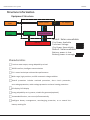
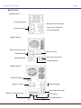
Hybrid Inverter
INSTALLATION AND OPERATION
USER MANUAL
Model number:XPI-Lxxxx-B series
Rev.1
Off Grid Solar Power system
Manual
1. Introduction
The manual includes the content of installation, operation and
application.
Please read the manual carefully before installation. All operation
MUST be taken by professional technician to ensure normal operation.
Keep the manual properly and take it as the reference at any time.
2. Mark and Symbol
Mark and symbol that referred in the manual.
! WARNING
△
Failure to follow the structions would harm personal safety, and
affect the reliability of the equipment or lose its data.
i
□
NOTE
Additional data and information
▲
Must step
Lists for Off Grid Solar Power system Model
Back View
Input Connection
Output
Connection
Battery
Connection
Back View-1
Input
Connection-1
Output
Connection-1
Battery
Connection-1
IG400-0120
Back View-2
Input
Connection-2
Output
Connection-2
Battery
Connection-2
IG400-0600
Back View-3
Input
Connection-3
Model
IG400-0080
Output
Connection-3
Battery
Connection-3
Off Grid Solar Power system
Manual
Content
Structure
Equipment Structure
--------------------------------------------------------------------------1
Safety
Proper Usage -------------------------------------------------------------------------------------2
Safety Caution -----------------------------------------------------------------------------------2
Emergency Situation ----------------------------------------------------------------------------3
Leakage Current --------------------------------------------------------------------------------3
Battery -------------------------------------------------------------------------------------------3
Repackage ----------------------------------------------------------------------------------------4
Transportion and Storage
Transportion-------------------------------------------------------------------------------------------------------5
Unpackage ---------------------------------------------------------------------------------------------------------5
Storage ------------------------------------------------------------------------------------------------------------ 5
Carriage ----------------------------------------------------------------------------------------------------------- 5
Back view
Back View-1 ------------------------------------------------------------------------------------------------ 6
Back View-2 ------------------------------------------------------------------------------------------------ 6
Installation
Environment ----------------------------------------------------------------------------------------------------7
Space Requirement --------------------------------------------------------------------------------------------7
----------------------------------------------------8
Max Current and Suggested Connection
External Protection Device -------------------------------------------------------------------8
Input Connection-1 ---------------------------------------------------------------------------9
Input Connection-2 ----------------------------------------------------------------------------9
Output Connection-1 --------------------------------------------------------------------------10
Output Connection-2 --------------------------------------------------------------------------10
Battery Connection-1 --------------------------------------------------------------------------11
Battery Connection-2 --------------------------------------------------------------------------11
Solar Panel Connection-1 ---------------------------------------------------------------------12
Solar Panel Connection-2 ---------------------------------------------------------------------12
Operation
Initial Operation ------------------------------------------------------------------------------13
Turn On Steps ---------------------------------------------------------------------------------13
Turn Off Steps ---------------------------------------------------------------------------------14
Function Test ----------------------------------------------------------------------------------14
Display Content Instruction
Display Content --------------------------------------------------------------------------------15
Maintenance
Battery Disposal -------------------------------------------------------------------------------16
Storage ----------------------------------------------------------------------------------------16
Cleaning ----------------------------------------------------------------------------------------17
Communication
Communication Interface Instruction
------------------------------------------------------18
---------------------------------------------------------------------19
Troubleshooting and Service
----------------------------------------------------------------------------20
Technical Specification
Off Grid Solar Power system
Manual
Structure information
Equipment Structure
▲
▲
Auto Switch
▲
AC Output
▲
City Power
Input
▲
Solar Panel
▲
Mppt solar
▲
Input
Charger
Charger/Inverter
▲
▲
State1: Solar unavailable
Battery
City Power Available
Transient Voltage
City Power Unavailable
State1: Solar available
Battery power is low
Battery power is enough
Characteristics
Ture sine wave output, strong adaptability to load
RS232 interface, Intelligent communication
CPU control technique with excellent performance
Wide range, high-precision, and full-automatic voltage stabilizer
Overall protection includes overload protection, short circuit protection,
over-voltage protection, under-voltage protection and over-heating protection.
LED display/ LCD display
Strong adaptability to city power, suitable for generator(optional)
Unattended function, can turn on/off automatically
Intelligent battery management, overcharging protection, as to extend the
battery working life
Off Grid Solar Power system
Safety
Proper Usage
1. The equipment supplies uninterrupted power for load
2. The equipment meets the information safety requirement, suitable
for office, home, commercial and bank etc.
3. With external battery can extend power supply time, external battery
connected as request.
WARNING
JFY takes the user’s personal safety in the most important position to
consider, therefore, the user or operator MUST read the steps carefully
and follow the rules strictly during operation.
Even if all switches have been turn off, there will be HIGH-VOLTAGE
DANGER inside the equipment. Any required operation to move and
open the protection plate MUST be finished by authorized technical
people.
Safety Caution
To make sure use the equipment safely, please follow instructions:
1. Please read the manual carefully before usage, overload usage is NOT
allowed.
2. If any fault, please cut off the power immediately and contact the
local agent.
3. If fire happened around, MUST use dry fire extinguisher. There will be
electric shock DANGER for using liquid fire extinguisher.
4. The equipment DOES NOT have switch for city power. JFY suggests
install a city power switch (>25A) in front of the equipment, in case to
cut down city power for emergency. Besides, connect the equipment
to the nearest socket in order to unplug to disconnect the equipment
and city power for emergency.
5. DO NOT place liquid container above the equipment, in order to avoid
the liquid pouring into cabinet and leads to short circuit, electric
shock or fire.
The equipment MUST be installed on good grounding environment to
ensure safety
Manual
Off Grid Solar Power system
Emergency situation
WARNING
All loads MUST be turned off before connecting to the equipment. When
fire happened to equipment, please DO NOT use water to put out the
fire.
Leakage Current
WARNING
Please connect grounding before other connection.
Wireless Interference
This equipment is A class Interference to other wireless products.
Equipment that sensitive to electromagnetic interference please DO NOT
get close to it, such as emitter, receiver, radar ,metal detector and so on.
Battery
Battery maintenance MUST be operated by authorized technician.
1. Internal or external battery both contains electrolyte. Normally,
please keep the battery dry. When battery damaged, the electrolyte
may leak out, and it’s harmful to eyes and skin. If that happened,
please flush immediately with plenty of clean water and go to hospital
for check.
2. The battery terminals have voltage, it will be DANGEROUS when
quantities of battery connect in series.
3. When battery terminal is short circuit or discharging of large current,
it will damage the battery and may cause fire.
4. Battery is sealed. It needs to charge the battery, even though full
charged in the past, after storage or NOT using for 6 months at 20ºC,
otherwise, it may cause battery failure. At this moment, it is required
to turn on the equipment to charge battery. If NOT following this
suggestion, it can NOT promise the normal working of it. We suggest
charge battery every 4 months.
Manual
Off Grid Solar Power system
Manual
5.After first charging, normally, the battery capacity is always less than
100%. It can only reach requirement after several times
charging/discharging cycle.
6.Avoid environment pollution, battery MUST be disposed according to
the rules and regulations for toxic or harmful waste
Repackage
Please follow below items for package:
6 hours after the final charging before package.
Place the equipment on the ventilative and bibulous material (like
100µm polyethylene)
Vacuum-packed NOT allowed
CH-4
Off Grid Solar Power system
Manual
Transport and Storage
Transport
It’s been fully checked before transport, please check if the package
damaged or NOT when receive the goods. If any damage or lackage,
please contact the local agent within 7 days after receiving.
Unpack
To avoid any damage, please be careful when carry the equipment and
check if all the packing materials complete or NOT.
Storage
After receiving the equipment, if it stays without use within 7 days,
please store it under storage condition, and ensure the equipment being
stored in a clean, dry environment with temperature 0ºC~35ºC.
Carriage
Equipment MUST be carried upright and carefully, any drop or fierce hit
may damage the equipment.
CH-5
Off Grid Solar Power system
Manual
Back View
Back View-1
Communication ...........
...........
Output Socket
...........
........... Battery Input Terminal
...........
Solar Input Terminal
...........
AC Input Socket
Back View-2
Battery Input Terminal ...........
Output Socket
...........
Battery Switch
...........
AC Input Socket ...........
Solar Input Terminal
Communication
Back View-3
Communication
Battery Switch
...........
...........
Output Socket
Solar Input Terminal
Battery Input Terminal
AC Output
AC Input Socket
CH-6
Off Grid Solar Power system
Manual
Installation
WARNING
The equipment
MUST be installed
by authorized
technician
in
compliance with local or national standard and law.
Environment
The equipment MUST be installed on the level shelf or ground, and with
proper temperature and humility.
NO materials placed on the equipment.
Working temperature for the equipment normally is 20 ºC ~ 35 ºC, ideal
is 15 ºC ~ 25 ºC and its Max. Continuous working hour is 8 hours when
reaches 40 ºC
Battery lifetime designed at the temperature 20 ºC , it will be decreased
to 50% when the temperature rises every 10 ºC.
Space Requirement
Leave a 25cm space on the upper part and around of the equipmen t to
ensure the ventilation.
25cm
25cm
25cm
Avoid direct sun
Avoid overheating
Avoid wet and liquid
Avoid dust
CH-7
Off Grid Solar Power system
Manual
Max. Current and recommended of cable’s diameter as following
( accoding to IEC-287 standard)
1)
PVC insulated copper wire (@70 ºC)
2)
Ambient temperature can be NOT higher than 40 ºC
3)
Larger cable MUST be used when can not meet the above 2 conditions
Max.Capacity(VA)
0.5KVA
Max.Capacity(KW)
0.4KW 5 0.6KW
Max.Input Current/A
.
0.7KVA 1KVA
2.8
1.5KVA
0.8KW 1.2KW
3.5
4.6
Input Diameter/mm²
Max.Output Current/A
1.8
2.5
3.6
Output Diameter/mm²
2KVA
1.5KW
2.5KW
7.5
9.2
13
1
1.5
1.5
5.5
7.2
10.9
1
1.5
1.5
1
1.5
1.5
3KVA
Grounding Wire Diameter
/mm ²
Table 1: The Max. Current of inverter and wiring specification
Max.Capacity(VA)
4KVA
5KVA
6KVA
7KVA
Max.Capacity(KW)
3.0KW
4.0KW
5.0KW
6.0KW
Max.Input Current/A
18
22
26
29
Input Diameter/mm²
2.5
4
6
6
Max.Output Current/A
14.5
18
21.8
25.4
Output Diameter/mm²
2.5
4
6
6
2.5
4
6
6
Grounding Wire Diameter
/mm ²
Table 2:
External Protection Device
External device MUST adopt appropriate breaker or fuse.
NOTE
The external battery MUST be near the equipment and adopt appropriate breaker
and fuse.
CH-8
Off Grid Solar Power system
Manual
Input Connection-1
Input Connection-2
Input Connection-3
CH-9
Off Grid Solar Power system
Manual
Output Connection -1
Output Connection -2
Output Connection -3
C H - 10
Off Grid Solar Power system
Manual
Batte「Y Connection -1
Batte「Y Connection -2
Batte「Y Connection -3
CH 11
Off Grid Solar Power system
Manual
Solar Panel Connection-1
Solar Panel Connection-2
Solar Panel Connection-3
CH 12
Off Grid Solar Power system
Manual
Operation
Initial Operation
Comply with following points before turning on the equipment to
supply the load:
Ensure a ventilative space
Ensure the earth wire well-connected
Ensure all the switches and switch of the external battery are in the
"OFF" position
Warning
Once the equipment is connected with city power, its output terminals
are all with electricity even not press key “ON” in the front.
DO NOT connect any loads that make the equipment overloaded,
especially the DC load, for example, hair drier and vacuum cleaner.
NOTE
If not follow the instruction strictly, it would lead to problem during
power supply
Turn on Steps
Turn the switch of the external battery to “ON”
Press key “ON” on the front board
Turn the switch of the city power to “ON”
Wait for at lest 30s until the output voltage is stable
Connect the equipment to the external loads one by one
Warning
If the equipment is overloaded, it will keep alarm, please take away some
loads and then start again
C H - 13
Off Grid Solar Power system
Manual
Turn Off Steps
NOTE
The following steps will shut down all the loads
Disconnect all the switches of the loads
Press key “OFF” in the front board
Turn the input switch to “OFF”
Turn the external battery switch to “OFF”
Ensure that every switch and breaker of the equipment is disconnected
Ensure that every indicator light goes out, and the equipment has been
shut down completely
Funtion Test
NOTE
Power during the test may be NOT stable, please DO NOT connect
primary loads to the equipment
While in test, break the city power to simulate interrupt, if the
equipment runs normally and there is a alarm, NOT from the inverter,
and sounds 4 times a minute while the battery discharges, and indicator
light for city power goes out, it means the equipment is running by
battery; If the alarm changes into one time per second, it means the
battery is short of power and will automatically turn off. During
emergency power supply, the load is powered by battery. Please NOTE
that charging the battery before operating the equipment.
C H - 14
Off Grid Solar Power system
Manual
Display Content Instruction
Indicator for Fault
Indicator for Inverter/Charger Work State
Indicator light for City Power
Battery Available
Load Display
Failure indication
LCD Display Content
INPUT: Voltage ; Frequency
BATTERY:
OUTPUT:
Voltage ;Battery percentage
Voltage ;Frequency
LOAD: Voltage ;Current
RE: PV Voltage ;Battery charging current
PV BAT Mode:PV mode
BAT Mode:Battery mode
AC Mode:City power mode
OV DC:Battery overvoltage
UV DC:Battery undervoltage
Over load :Over load
C H - 15
Off Grid Solar Power system
Manual
Maintenance
Battery Disposal
Battery in the equipment NO need the user to maintain. When the
battery reaches the end of the service life, it MUST be replaced by
customer service technician. The waste battery is poisonous and harmful
and MUST be disposed by the recycling center approved by local law.
Usually, service life of the battery is about 3 years under ambient
temperature 25℃, while at the same time, it is affected by the frequency
of city power interrupt and duration.
NOTE
To ensure the good condition of battery, and on the premise that there is
enough power of it, under common conditions, the battery should be
periodic tested every 4~6 months. The test is to discharge the battery to
the loads till shut down and then continuously charge the battery NOT
less than 12 hours. Please NOTE that to avoid deep discharge and
damage the battery, it MUST discharge with up to 50% load capacity.
Storage
For long-term storage, when the ambient temperature is ≤25℃, the
battery MUST be charged every 4 months, and no less than 12 hours
every time; when the ambient temperature is ≥25℃, the battery MUST
be charged every 2 months, and no less than 12 hours every time;
C H - 16
Off Grid Solar Power system
Manual
Cleaning
Press ON-OFF key to shut down the equipment and break the city power input
Use dry or wet cleaning cloth to clean the surface
Warning
DO NOT use cleaning mixture or corrosive solvent to clean the
equipment
DO NOT let the liquids flow into the equipment
Ensure the venthole unobstructed
C H - 17
Off Grid Solar Power system
Manual
Communication
RS232 communication interface is available for UPS in the equipment,
data exchange is achievable between device and PC. Request of it please
contact local distributor.
RS232 Interface Instruction (Limit to UPS model ONLY)
RS232 communication interface is available, the user can monitor input
power, state of the equipment and its running.
NOTE
Connection of the RS232 MUST adapt attached specialized cable
RS232 data
Baud Rate: 2400bps
Bits Length: 8bit
Cut-off: 1bit
Parity Bit: none
Following is the instruction for pin-out of DB-9
Pin-out
Instruction
Input
Output
Grounding
RS232 Connection pore
Sheet 3 RS232 pin-out instruction
C H - 18
Off Grid Solar Power system
Manual
Troubleshooting and Service
Please check the below items before contacting the customer service
technician when there is problem for the equipment.
If connection of the external battery is correct or NOT
If there is city power input , its voltage and frequency matches our
standard, or NOT
If the input fuse has been damaged or the breaker has been shut down,
or NOT
Please provide below information when contact the customer service
technician
Equipment information: model, order No and serial No. on its back
Detail of the problem, such as types of load, frequency of the problem,
indicator light and alarm situation
Service
NOTE: if the equipment needs to repair, please follow the blew steps.
Send it back to local agent if problem occurs again.
For general problems, please take troubleshooting for reference
If there is still problem, please contact the local agent
Record the model, serial No. and date of purchase of the equipment and
then contact the customer service technician for troubleshooting.
During warranty, no-artificial damage is free for repair, if \NOT, repair charges.
During the transportation, ensure it is well packed to avoid damage
NOTE: DO NOT use styrofoam pad for package. Damage during the
transportation is NOT guaranteed, please effect whole insurance for
the parcel.
C H - 19
Off Grid Solar Power system
Manual
Technical Specification
MODEL(IG)
0.5KVA 0.7KVA 1.0KVA
BatteryVoltage(dc)
BatteryConfiguration
OutputPower
1.5KVA
2.0KVA 3.0KVA 4.0KVA 5.0KVA 6.0KVA 7.0KVA
24V
Inside max.200AH*2pcs
or External
0.4KW 0.6KW 0.8KW
1.2KW
1.5KW
2.5KW 3.0KW
4.0KW 5.0KW 6.0KW
Charger Type
Rated PVInputPower
1440W
PVInputVoltageRange
30-90Vdc
MaxSolar Charge
Current
FloatCharge Voltage
5760W
2880W
27.2Vdc
EqualizationCharge
Voltage
28.8Vdc
AC InputVoltage
200 255
AC InputFrequency
ChargingCurrent
AC OutputVoltage
580*560*534
420*145*215
26.5/8
27.5/9
28.5/10
580*560*857
500*195*345
45/11
46/19
500*240*490
47/22
35
40
45
54