1
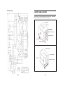
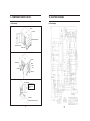
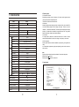
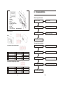
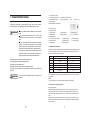
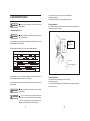
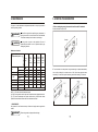
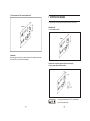
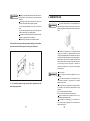
R
WUXI KIPOR POWER CO., LTD.
DIGITAL DIESEL
GENERATOR SET
ID6000
PREFACE
Thank you for purchasing our generators.
This manual covers operation and maintenance of ID6000 generator.
All information in this publication is based on the latest product information available at
the time of approval for printing.
We reserve the right to make changes at any time without notice and without incurring
any obligation.
No part of this publication may be reproduced without written permission.
This manual should be considered a permanent part of the generator and should be
reserved with it if it is resold.
Pay special attention to statements preceded by the following words:
DANGER
Failure to properly follow these precautions can result in
serious injury or DEATH!
WARNING
Failure to properly follow these precautions can result in
property damage, serious injury or DEATH!
CAUTION
The generators are designed to give safe and dependable
service if operated according to instructions. Failure to do so
could result in personal injury or equipment damage.
If a problem should arise, or if you have any questions about the generator, consult an
authorized dealer.
WARNING
Indicates a possibility of personal injury or equipment damage
if instructions are not followed.
Read and understand the Owner's Manual before operating
the generator.
Operate only in well ventilated areas. Exhaust gas contains
poisonous carbon monoxide, and can be deadly.
Always stop engine before refueling. Wait 5 minutes before
restarting.
Check for spilled fuel or leaks. Clean and/or repair before use.
Keep any sources of ignition away from fuel tank at all times.
CONTENTS
1. SAFETY INSTRUCTIONS
1
2. SAFETY LABEL LOCATIONS
3
3. COMPONENT IDENTIFICATION
4
4. PRE-OPERATION CHECK
8
5. STARTING THE ENGINE
11
6. GENERATOR USE
13
7. STOPPING THE ENGINE
17
8. MAINTENANCE
18
9. TRANSPORTING/STORAGE
22
10. TROUBLESHOOTING
23
11. SPECIFICATIONS
24
12. ELECTRICAL WIRING DIAGRAM
25
13. APPENDIX
26
2. The choice of the electric cable
The choice of the electric cable depends on the allowable current of the cable
and the distance between the load and the generator. And the cable section
should be big enough.
If the current in the cable is bigger than the allowable current, it will become over
hot and the cable will be burnt. If the cable is long and thin, the input voltage of
the electric appliance will be not enough, causing that the generator doesn't start.
In the following formula, you can calculate the value of the potential "e".
Potential (v) =
1
Length
58
Section area
Current (A)
1. SAFETY INSTRUCTION
WARNING
3
The relations among of the allowable current, and length, section of the Insulating
cable (single core, multi-core) are as follow:
(Presume that the use voltage is 220V and the potential is below 10V.
WARNING
Ambient temperature
25
Single core
Current capacity
(25 )(A)
Voltage
Drop
mv/M
Three cores
Current capacity
(25 )(A)
Voltage
Drop
mv/M
Four cores
Current capacity
(25 )(A)
Voltage
Drop
mv/M
No.
Copper
cables model
VV22
YJV22
VV22
YJV22
VV22
YJV22
VV22
1
1.5mm
2
20
25
30.86
13
18
30.86
13
13
20
2
2.5mm2
28
35
18.9
18
22
18.9
18
30
28
3
4mm2
38
50
11.76
24
32
11.76
25
32
38
2
4
6mm
48
60
7.86
32
41
7.86
33
42
48
5
10mm
2
65
85
4.67
45
55
4.67
47
56
65
6
16mm2
88
110
2.95
61
75
2.6
65
80
88
7
25mm2
113
157
1.87
85
105
1.6
86
108
113
8
35mm
2
142
192
1.35
105
130
1.2
108
130
142
9
50mm
2
171
232
1.01
124
155
0.87
137
165
171
10
70mm2
218
294
0.71
160
205
0.61
176
220
218
11
95mm2
265
355
0.52
201
248
0.45
217
265
265
12
120mm
2
305
410
0.43
235
292
0.36
253
310
305
13
150mm
2
355
478
0.36
275
343
0.3
290
360
355
14
185mm2
410
550
0.3
323
400
0.25
333
415
410
15
240mm2
490
660
0.25
381
480
0.21
400
495
490
WARNING
The generators are designed to give safe and dependable
service if operated according to instructions.
Read and understand the Owner's Manual before operating
the generator. Failure to do so could result in personal injury
or equipment damage.
Please use light diese. Gasoline and pafaffin is not allowed
to use
Exhaust gas contains poisonous carbon monoxide. Never
run the generator in an enclosed area. Be sure to provide
adequate ventilation.
Generator should be earthed with a wire to avoid electric
shock
The muffler becomes very hot during operation and
remains hot for a while after stopping the engine.
Be careful not to touch the muffler while it is hot.
Let the engine cool before storing the generator indoors.
The engine exhaust system will be heated during operation
and remain hot immediately after stopping the engine.To
prevent scalding, pay attention to the warning marks attached
to the generator.
Battery charge should be carried out in the place with good
ventilation. Smoke and spark is forbidden.
Note: The variation of temperature and the laying of cables will influence the current capacity
of cables, the table above is just used for reference.
-
-
- -
Ensure safe operation
WARNING
Gasoline is extremely flammable and explosive under
certain conditions. Refuel in a well ventilated area with
the engine stopped.
Keep away from cigarette, smoke and sparks when
refueling the generator, Always refuel in a well-ventilated
location.
Wipe up spilled gasoline at once.
13. APPENDIX
1. Modified coefficient table of ambient condition power
The conditions of generator rated output:
Altitude: 0 m
WARNING
WARNING
Connections for standby power to a building's
electrical system must be made by a qualified electrician
and must comply with all applicable laws and electrical
codes. Improper connections can allow electrical current
from the generator to back feed into the utility lines. Such
back feed may electrocute utility company workers or
others who contact the lines during a power outage, and
when utility power is restored, the generator may
explode, burn, or cause fires in the building's electrical
system.
Always make a pre-operation inspection before you
start the engine to prevent an accident or equipment
damage.
Place the generator at least 1m away from buildings
or other equipment during operation.
Operate the generator on a level surface. if the
generator is tiled, fuel spillage may result.
Know how to stop the generator quickly and
understand operation of all the controls. Never permit
anyone to operate the generator without proper
instructions.
Keep children and pets away from the generator
when it is in operation.
The generator is a potential source of electrical
shocks when misused; do not operate with wet hands.
Do not operate the generator in rain or snow and do
not let it get wet to avoid electric shock.
Ambient temperature: 25
Relative humidity: 30%
Ambient modified coefficient: C (Relative humidity 30%)
Ambient temperature (
Altitude
(m)
)
25
30
35
40
45
0
1
0.98
0.96
0.93
0.90
500
0.93
0.91
0.89
0.87
0.84
1000
0.87
0.85
0.82
0.80
0.78
2000
0.75
0.73
0.71
0.69
0.66
3000
0.64
0.62
0.6
0.58
0.56
4000
0.54
0.52
0.5
0.48
0.46
Note: When the relative humidity is 60%, the modified coefficient is C-0.01
When the relative humidity is 80%, the modified coefficient is C-0.02
When the relative humidity is 90%, the modified coefficient is C-0.03
When the relative humidity is 100%, the modified coefficient is C-0.04
Counting example:
When the rated power of generator is PN =5KW, altitude is 1000m, ambient
temperature is 35
P=PN
- -
(C-0.02) = 5
, relative humidity is 80%, the rated power of generator is:
(0.82-0.02) = 4KW
-
-
12.2 Single voltage
2. SAFETY LABEL LOCATION
These lables warn you potential hazards that can cause serious injury. Read the labels
and safety notes and precautions described in manual carefully.
Fuel use sticker
Hook sticker
Low oil pressure
warning sticker
Operation warning sticker
Battery power warning
Generator parameter sticker
Frequency sticker
Outdoor use sticker
Fuel warning sticker
Model sticker
High temperature sticker
-
-
- -
3. COMPONENT IDENTIFICATION
12. ELECTRIC DIAGRAM
1. Profile drawing
12.1 Dual voltage
Boom
Fuel filler
Muffler exhaust pipe
Maintenance door
Starter motor
Cover plate of fuel filler
Handle
Diesel filterr
Panel
Module
Battery
Air filter
Side door
Air filter sticker
1. Battery maintenance
cover plate
2. Battery fixing belt
3. Battery
Series No
Battery maintenance sticker
- -
-
-
2. Electric system
11. SPECIFICATION
Model
Rated frequency (Hz)
ID6000
50
60
Rated output (kVA)
5
Max. output (kVA)
5.5
Rated voltage (V)
115/230
Rated current (A)
43.5/21.7
120/240
41.7/20.8
1700-3300
Rated rotation speed (r/min)
Alternator
Model
KD70
Motor type/Converter type Multi-pole permanent magnet motor /IGBT digital converter
Loop type
Single phase three loops
Power factor(COS )
1
Insulation grade
F
Model
Cylinder type
KD186FGETi
Vertical single cylinder, four stroke, air cooled, direct injection
86
BoreXStroke
Displacement
Engine
Note:
Engine speed range should be according with the AC inverter total output power:
Rated low speed
zero load
Rated high speed
Rated max. output power
75
436
19.6 1
Compression ratio
Rated power
6.3/3600
Pressure splash
Lub. mode
Lubricant
Above CD grade or SAE10W 30
Lubricant capacity
3. Control panel
15W 40
1.65
Output indicator lamp (Green)
Starting system
Electric starter
Battery capacity
12V 36Ah
Fuel type
2.1 Elements and function
Digital diesel generator consists of alternator, AC inverter, electric regulator, electric
control system, harness and output/input units.
The functions of each units are listed as follow:
2.2 Alternator:
Alternator adopts permanent magnet generator, consisting of stator, rotor and shell. The
rotor without bearings adopts one piece design with engine£¨Fixed at one side of
crankshaft£©
, brushless and natural draft. The stator adopts multi-pole and multi-voltage
windings. It is rotates with the crankshaft to outuput three phase AC. The generator
features small volume, simple structure and high efficiency.
2.3 AC inverter:
AC voltage output by alternator is rectified and inverted for AC loads. AC inverter
module includes protection for overload, over voltage, over frequency, over heat etc.
2.4 Electric regulator:
Electric regulator features convenient installation, rapid response, good regulation and
safety.
It can automatically regulate the engine speed depending on the loads to ensure the
best economics
Diesel: 0 (summer), 10
Fuel consumption
(winter), 35
340
Fuel tank capacity
14.5
Continuous running time (hr) (at rated output)
6.5
62-69
Noise (zero load- full load)
875
Dimension (LxXWXH)
530
168
Net weight
750
Overload alarm lamp(Red)
Low oil level alarm lamp(Red)
(chilliness)
Over speed alarm lamp (Red)
1. Socket
2. Breaker
3. LCD monitor
4. Lamp
5. Electric lock (start switch)
6. Conjoined socket
7. Socket
8. Earthing end
9. Reset switch
10. Energy saving switch
Dual voltage panel
Silent
Structure
-
-
- -
10. TROUBLE SHOOTING
Output indicator lamp (Green)
Overload alarm lamp (Red)
Low oil level alarm lamp (Red)
Over speed alarm lamp (Red)
1. Socket
2. Breaker
3. LCD monitor
4. Lamp
5. Energy saving switch
6. Electric lock (start switch)
7. Earthing end
8. Socket
9. Reset switch
Single voltage panel
10. ATS option switch
When the engine will not start:
Is there fuel in the tank?
No
Refill the fuel tank.
Yes
Is there enough oil in the engine?
No
Add the recommended oil.
Yes
3.1. LCD instruction:
Is the battery voltage 12 to 15V?
No
Replace or charge the battery
Key
Screen
Yes
Take the generator to an authorized dealer.
The engine fails to run with load:
3.1.1 Instructions of dual voltage connector
Is the output indicator lamp on
No
Take the generator to an authorized dealer
No
Turn on the breaker.
Yes
Item
Function
Item
Function
Item
9
B phase current transformer input
10
B phase current transformer input
Function
1
A phase AC voltage input
5
2
B phase AC voltage input
6
5 6 out external switch,
Series connection when closed
Parallel connection when open
3
A phase AC voltage input
7
A phase current transformer input
11
External battery GND
4
B phase AC voltage input
8
A phase current transformer input
12
External battery 12V
Is the AC breaker switched on?
Yes
Is the overload indicator lamp on?
Is the electric appliance in good condition?
Function
Item
Function
Item
1
AC voltage input
4
Relay control signal output (+12v)
7
External battery GND
2
AC voltage input
5
Current transformer input
8
External battery 12V
3
Current transformer input
6
Relay control signal output (GND)
9
- -
Lower down the load or replace the generator for a larger one
Yes
3.1.2 Instructions of single voltage connector
Item
Yes
Function
Yes
Replace or charge the electric appliance
Yes
Take the generator to an authorized dealer.
-
-
9. TRANSPORTING/STORAGE
l spillage when transporting or during temporary storage, the genera-tor should be
secured upright in its normal operating position, When transporting the generator:
WARNING
Do not overfill the tank (there should be no fuel in the filler
neck)
Do not operate the generator while it is on a vehicle. Take
the generator off the vehicle and use it in a well ventilated
place.
Avoid a place exposed to direct sunlight when putting the
generator on a vehicle. If the generator is left in an enclosed
vehicle for many hours, high temperature in-side the vehicle
could cause fuel to vaporize resulting in a possible explosion.
?Do not drive on a rough road for an extended period with the
generator on board, if you must transport the generator on a
rough road, drain the fuel from the generator beforehand.
Before long while storag, the following items should be done:
(1) Run the generator for 5 minutes without any load.
(2) Drainage the oil and refill the new oil.
(3) Drainage the fuel to a clean container and clean the fuel tank.
(4) Clean the dirty in generator. Seal the generator with a plastic cover for safekeeping
in dry place.
WARNING
Fuel is explosive and flammable. Smoke, fire and spark are
forbidden.
1. For example LCD-230V
1---Genset output voltage (V); 2---Genset current with load (A);
3---Genset frequency (Hz);
4---Genset running time
Code
5---Battery voltage.
Shift the parameters by the button
2. LCD-120V / 240V
(1) Output in parallel:
1---output voltage;
4---output current;
7---Running time;
8---Battery voltage;
(2) Output in series:
1---Sum of A, B phase voltage;
2---A phase voltage;
4---A phase current;
5---B phase current;
7---Running time;
8---Battery voltage;
Parameter
Key
6---output frequency;
(2 3 5 are shielded)
3---B phase voltage;
6---output frequency;
3.1.3 Maintenance information
1. Maintenance will be reminded after specific running time. LCD lamp twinkles and the
codes will be displayed. If there is many codes, they may be displayed in turns at an
interval of 3 seconds if there is many codes.
Item
Maintenance information
Code
1
Oil
SV 1
2
Oil filter
SV 2
3
Air filter
SV 3
4
Nozzle pump
SV 4
5
Valve clearance
SV 5
6
Tank and filter
SV 6
2. Press the button to read the parameters. Release the key for 2 seconds to have the
maintenance
Remind.
3. Press the button for 5 seconds to clear the maintenance information.
3.2 Instruction of energy saving switch:
Energy saving switch
When Energy saving switch locates the side of "OFF" the speed of engine varies
when output power varies. Power increases while speed increases. Engine will run
under the low speed without any load; the total machine will work in perfect economic
state.
When Energy saving switch locates the side of "ON" Engine will run under the max.
speed. Inverter module reaches max. power. This mode must be used during sudden
load and unload.
-
-
- -
a. Open the left door, loose the hoop and remove the diesel filter
b. Replace the diesel filter
c. Reinstall the filter element. Fix the hoop and close the left door.
4. PRE-OPERATION CHECK
Be sure to check the generator on a level surface with the
engine stopped
WARNING
4. Pump maintenance:
Do not dismantle the pump randomly. Please contact KIPOR dealer if special tools are
required for pump replace and clean.
1. Check the engine oil level
Using nondetergent oil or 2-stroke engine oil could shorten
the engine's service life.
WARNING
Air filter sticker
1. battery maintenance
cover plate
2. battery fixing belt
3. battery
Use a high-detergent, premium quality 4-stroke engine oil. certified to meet CC or CD
grade SAE10W-30 oil is recommended.
Select the appropriate viscosity of oil according to the ambient temperature.
Viscosity---Ambient temperature
Single grade
Ambient
temperature -30
SAE40
50
SAE20 20W
SAE10W
-25
-20
-15
-10
SAE30
-5
0
5
10
15
20
25
30
Genset code
SAE10W/30
Multi grade
SAE15W/40
Battery maintenance sticker
SAE5W/20
SAE5W/30
SAE Viscosity grade table
Open the left door, Loose the cap and wipe the dipstick with a clean rag. Check the oil
level by inserting the dipstick in the filler hole after fastened.
If the oil level is below the end of the dipstick, refill the recommended oil up to the top of
the oil filler neck.
WARNING
CAUTION
5. Battery maintenance
a. Unscrew the bolts on cover plate, remove the cover plate
b. Remove the fixing belt
c. Replace the battery and fasten the fixing belt, install the cover plate, fasten the bolts
and close the side door.
Running the engine with insufficient oil can cause serious
engine damage.
The Low Oil Alarm System will automatically stop the
engine before the oil level falls below the safe limit. However,
to avoid the inconvenience of an unexpected shutdown, it is
still advisable to visually inspect the oil level regularly
- -
-
-
For enviroment protection, we recommend that the waste
oil should be kept in seal containers and send to the repair
agency and recycling center. Do not drain the oil to the ground
or rubbish.
CAUTION
Dipstick
Upper level
Oil filler
2. AIR CLEANER SERVICE
Lower
level
A dirty air cleaner will restrict air flow to the engine cylinder. To prevent it, service the air
cleaner regularly. Service more frequently when operating the generator in extremely
dusty areas.
Do not use gasoline or low flash point solvents for cleaning.
They are flammable and explosive under certain conditions.
Please replace the filter element if power is reduced or
exhaust smoke color is abnormal.
Do not run generator without air cleaner for causing engine
accelerated wear.
CAUTION
2. Check the fuel level
a. Open the side door.
b. Loose the nut on filter cap, disconnect the cap.
c. Take out the air filter
d. Clean the dirty on filter element, but detergent is not allowed.
e. Re-install the filter element, lock the cap and close the side door.
Use automotive light diesel.
If the fuel level is low, refuel the fuel tank until the level increased to the specified mark.
Never use an oil/diesel mixture or dirty diesel.
Avoid getting dirt, dust or water in the fuel tank.
After refueling, tighten the oil rule seurely.
WARNING
Air filter bottom shell
Air filter bottom seal
Air filter element
Seal ring of air filter shell
Air filter cap
Thumb nut
Diesel is extremely flammable and is explosive under
certain conditions.
Refuel in a well-ventilated area with the engine stopped. Do
not smoke or allow flames or sparks in the area where the
engine is refueled or where fuel is stored.
Do not overfill the fuel tank (there should be no fuel above
the upper limit mark). After refueling, make sure the tank cap is
closed properly and securely.
Be careful not to spill fuel when refueling. Spilled fuel or fuel
vapor may ignite, If any fuel is spilled, make sure the area is
dry before starting the engine.
Avoid repeated or prolonged contact with skin or breathing
of vapor. KEEP OUT OF REACH OF CHILDREN
3. Fuel filter maintenance
A dirty fuel filter will restrict fuel flow to pump. To prevent it, service the fuel filter
regularly.
-
-
- -
a. Open side door, unscrew the dipstick.
b. Drain the dirty oil to a container
Cover plate of fuel filler
Tank cap
Tank cap
Upper level
Oil level indicator
Filter net
c. Refill the recommended oil to the oil filler level and check it
d. screw the dipstick and close the side door
Oil capacity: KD186FGETi
Engine: 1.65 L.
Oil dipstick
3. Check the air cleaner
Check the air cleaner element to be sure it is clean and in good condition.
Open the right door, loose the nut and remove the cap to check the filter element.
Clean or replace the element if necessary.
Oil drainage hole
Oil drainage bolt
Air filter bottom shell
Air filter bottom seal
Air filter element
Seal ring of air filter shell
Dipstick
Upper limit
Air filter cap
Oil filler
Thumb nut
Lower
limit
CAUTION
Never run the engine without the air cleaner. Rapid engine
wear will result from contaminants.¡£
4. Check fuel filter
Check the fuel filter to be sure it is clean and in good condition. Open the left door,
check the filter element. Clean or replace the element if necessary.
-
-
-
-
8. MAINTENANCE
5. STARTING THE GENERATOR
The purpose of the maintenance and adjustment schedule is to keep the generator in
the best operating condition.
1. Before starting the genset, disconnect the load from the DC terminals.
Ensure the breaker is kept at "OFF"
Shut off the engine before performing any maintenance. If
the engine must be run, make sure the area is well ventilated.
The exhaust contains poisonous carbon monoxide gas.
WARNING
Breaker
Use genuine our parts or their equivalent. The use of
replacement parts which are not of equivalent qual-ity may
damage the generator.
CAUTION
Maintenance Schedule
Item
Regular service period
First
month
or
20 hours
Each
use
Every 3
months
or
50 hours
Every 6
months
or 100
hours
Every
year
or 200
hours
(after second time)
(after second time)
2. Turn the switch to the start position, then generator begins to preheat automatically.
(Replace)
Loose it after all lamps lit, the switch returns to "ON", which means generator starts
successfully. For start failure, please restart the generator after waiting for 10 minutes.
Check
Oil
Replace
Oil filter
Air filter
Nozzle pump
(first time)
Check and replace
Check
(2)
Clean
(3)
Clean adjust
(3)
Valve clearance Check adjust
Tank and filter
Clean or replace
Oil circuit
Check
Every 2 years(replace if necessary)(3)
NOTE: (1) "O" means normal maintenance interval
(2) "O(2)" means generator used in dirty area. Please shorten the maintenance interval
(3) "O(3)" means maintenance and repair should taken by KIPOR dealer unless
professionals are available. Please refer to the maintenance manual.
1. CHANGING OIL
Run generator for 3
heated.
WARNING
5 minutes and stop it. Drain the oil quickly when the generator is
Ensure the generator is stopped before drainage.
-
-
-
-
3. Turn the breaker to "ON", connect with the loads.
7. STOPPING THE ENGINE
To stop the engine in an emergency, turn the engine switch to the OFF position.
Breaker
IN NORMAL USE:
1. Turn the breaker to "OFF".
Breaker
4. Instruction:
Engine can keep the rated power in standard ambient. If the ambient varies, please
refer to GB/T6072.1 for power and fuel consumption.
2. Switch off the connected equipment and pull the inserted plug.
3.Turn the engine switch to the OFF position.
Turn the generator start switch to "OFF", cut off the battery
power for a long while storage
-
-
-
-
WARNING
Battery is easily flammable and vaporized. Keep away from
the spark and fire. Charge the battery in the place with good
ventilation.
Electrolyte contains sulfuric acid which may burn the skin
and eyes. Please wear mask and protective clothes.
(1) If the electrolyte splashes to skin, wash off by water at
once
(2) If the electrolyte splashes to eyes, please wash it by water
at least 15 minutes, then go to hospital quickly.
If electrolyte is swallowed, please drink much water and milk,
magnesia or vegetable oil and go to hospital.
Please charge in the place out of the reach of children.
6. GENERATOR USE
WARNING
To prevent electrical shock from faulty appliances, the
generator should be earthed. Connect a length of heavy wire
between the generator's earth terminal and an external ground
source.
6.3 Overload DC circuit may result in the protector tripping. In this condition,
please disconnect DC load and press the reset key on control panel.
ON
Connections for standby power to a building's electrical
system must be made by a qualified electrician and must
comply with all applicable laws and electrical codes. Improper
connections can allow electrical current from the generator to
backfeed into the utility lines. Such backfeed may electrocute
utility company workers or others who contact the lines during
a power outage, and when utility power is restored, the
generator may explode, burn, or cause fires in the building's
electrical system.
OFF
WARNING
6.4 For electrical equipment, Large current will be generated when the
motor drving system starts.
-
-
Do not overload.
Do not exceed the current limit specified for any one
receptacle.
Do not connect the generator to a household circuit. This
could cause the damage to the generator or to electrical
appliances in the house.
Do not modify or use the generator for other purposes than
it is intended for. Also observe the following when using the
generator.
A. Do not connect generators in parallel.
B. Do not connect an extension to the exhaust pipe.
When an extension cable is required, be sure to use a
tough rubber sheathed flexible cable.
Limit length of extension cables: 60 m for cables if 1.5
mm2 100m for cables of larger than 2.5 mm2 and the current
capacity within 5A/ mm2.
-
-
CAUTION
Keep the generator away from other electric cables or wires
such as commercial power supply lines.
DC receptacle is availabe for DC power
The total power shouldn't exceed the sum of AC and DC
power if AC and DC power are used at same time.
For most equipment, the motor needs the power higher
than rated value for starting
If red lamp is on, stop the engine and find out the reason.
Check the load condition before they are connected to the
WARNING
generator
Red and green lamp may be on at the same time during
geneartor starting. If red lamp is off after 4 seconds, it means
the generator is in normal; if the red lamp still keeps on,
please contact KIPOR dealer.
6.1 AC applications
1. Start the engine and make sure the output indicator light (green) comes on.
2. Confirm that the appliance to be used is switched off, and plug in the appliance.
WARNING
Overload indicator lamp (red) is on for a long while,
generator may be damaged; although overload indicator lamp
is on a short while, the generator service lift may still be
shortened.
Be sure that all appliances are in good working order
before connecting them to the generator. If an appliance
begins to operate abnormally, becomes sluggish, or stops
suddenly, turn off the generator engine switch immediately.
Then disconnect the appliance, and examine it for signs of
malfunction.
3. Low oil level alarm
This system is designed for protecting engine due to lackage of oil. It will stop the
engine automatically if the oil level of crankshaft box is below the safe value. (generator
switch still keeps in "ON" position). If customers restart the engine, the alarm lamp(red)
will twinkle, and the engine can't be started. Please add the oil in this condition.
Ouput indicator lamp (green)
Overload alarm lamp(red)
Low oil level alarm lamp(red)
Over speed alarm lamp (red)
4. Over speed alarm
Generator will stop at once and alarm lamp will be on if engin is over speed for (0.5
seconds).
Ouput indicator lamp (green)
6.2 Output and Overload Indicators
Overload alarm lamp(red)
1. In normal condition, ouput indicator lamp (green) is on
Low oil level alarm lamp(red)
Ouput indicator lamp (green)
3
Over speed alarm lamp (red)
Overload alarm lamp(red)
Low oil level alarm lamp(red)
WARNING
Over speed alarm lamp (red)
2. If generator overloads (more than 5.5kVA), or loads have short circuit
ouput
indicator lamp (green) will be off while overload lamp(red) will be on. At this time the
current to loads will be cut off
To avoid spark, please connect the charge cable to
generator first, then connect the battery. During dismantling,
remove the battery first.
Do not confuse the + and - pole, or the generator and
battery will be damaged.
Ouput indicator lamp (green)
Overload alarm lamp(red)
Low oil level alarm lamp(red)
DANGER
Over speed alarm lamp (red)
-
-
For car battery charge application, disconnect the battery
earth cable before connecting to the generator. During
dismantling, disconnect the charge cable before earthing,
which will prevent the short circuit and spark.
Do not start the car if the genetor sill keep connecting with
the car.
-
-