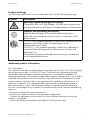
1
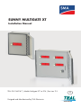
SUNNY MULTIGATE XT Installation Manual TEAL PN 1060147 | Models Multigate XT1 to XT4 | Revision 2.5 Designed and Manufactured by TEAL Electronics US TEAL Electronics 2 SMA America, LLC Installation Manual - TEAL PN 1060147 rev 2.5 TEAL Electronics SMA America, LLC Copyright © 2013 TEAL Electronics. All rights reserved. Some portions of this document are protected under Copyright © 2012 and 2013 SMA America, LLC. All rights reserved. No part of this document may be reproduced, stored in a retrieval system, or transmitted, in any form or by any means, electronic, mechanical, photographic, magnetic or otherwise, without the prior written permission of SMA America, LLC and TEAL Electronics. Neither SMA America, LLC nor TEAL Electronics makes representations, express or implied, with respect to this documentation or any of the equipment and/or software it may describe, including (with no limitation) any implied warranties of utility, merchantability, or fitness for any particular purpose. All such warranties are expressly disclaimed. Neither SMA America, LLC nor its distributors or dealers nor TEAL Electronics nor its distributors or dealers shall be liable for any indirect, incidental, or consequential damages under any circumstances. (The exclusion of implied warranties may not apply in all cases under some statutes, and thus the above exclusion may not apply.) Specifications are subject to change without notice. Every attempt has been made to make this document complete, accurate and up-to-date. Readers are cautioned, however, that SMA America, LLC and TEAL Electronics reserve the right to make changes without notice and shall not be responsible for any damages, including indirect, incidental or consequential damages, caused by reliance on the material presented, including, but not limited to, omissions, typographical errors, arithmetical errors or listing errors in the content material. All trademarks are recognized even if these are not marked separately. Missing designations do not mean that a product or brand is not a registered trademark. SMA America, LLC 3801 N. Havana Street Denver, CO 80239 U.S.A. TEAL Electronics 10350 Sorrento Valley Road San Diego, CA 92121 U.S.A. Installation Manual - TEAL PN 1060147 rev 2.5 3 TEAL Electronics SMA America, LLC IMPORTANT SAFETY INSTRUCTIONS SAVE THESE INSTRUCTIONS This manual contains important instructions for the Multigate XT enclosure product family. This manual must be followed during installation and maintenance. The products are designed and tested according to international safety requirements, but as with all electrical and electronic equipment, certain precautions must be observed when installing and/ or operating the products. To reduce the risk of personal injury and to ensure the safe installation and operation of the products, you must carefully read and follow all instructions, cautions and warnings in this manual. Warnings in this document A warning describes a hazard to equipment or personnel. It calls attention to a procedure or practice, which, if not correctly performed or adhered to, could result in damage to or destruction of part or all of the SMA equipment and/or other equipment connected to the SMA equipment or personal injury. Symbol Description DANGER indicates a hazardous situation which, if not avoided, will result in death or serious injury. WARNING indicates a hazardous situation which, if not avoided, could result in death or serious injury. CAUTION indicates a hazardous situation which, if not avoided, could result in minor or moderate injury. NOTICE is used to address practices not related to personal injury. 4 Installation Manual - TEAL PN 1060147 rev 2.5 TEAL Electronics SMA America, LLC Product markings The following symbols are used as product markings with the following meanings. Symbol Description Warning regarding dangerous voltage The product works with high voltages. All work on the product must only be performed as described in the documentation of the product. Observe the operating instructions Read the documentation of the product before working on it. Follow all safety precautions and instructions as described in the documentation. UL-1741 is the standard applied by Underwriters Laboratories to the product to certify that it meets the requirements of the National Electrical Code®. UL-61010-1 is the standard applied by Underwriters Laboratories to specify Electrical Equipment For Measurement, Control, and Laboratory Use. The product has been certified by Intertek as being in accordance with the applicable directives. Additional product information FCC Information: This equipment has been tested and found to comply with the limits for a Class B digital device, pursuant to part 15 of the FCC Rules. These limits are designed to provide reasonable protection against harmful interference in a residential installation. This equipment generates, uses and can radiate radio frequency energy and, if not installed and used in accordance with the instructions, may cause harmful interference to radio communications. However, there is no guarantee that interference will not occur in a particular installation. If this equipment does cause harmful interference to radio or television reception, which can be determined by turning the equipment off and on, the user is encouraged to try to correct the interference by one or more of the following measures: —Reorient or relocate the receiving antenna. —Increase the separation between the equipment and receiver. —Connect the equipment into an outlet on a circuit different from that to which the receiver is connected. —Consult the dealer or an experienced radio/TV technician for help. Installation Manual - TEAL PN 1060147 rev 2.5 5 TEAL Electronics SMA America, LLC General Warnings General Warnings All electrical installations must be done in accordance with the local and National Electrical Code® or ANSI/NFPA 70. This document does not and is not intended to replace any local, state, provincial, federal or national laws, regulation or codes applicable to the installation and use of the product, including without limitation applicable electrical safety codes. All installations must conform with the laws, regulations, codes and standards applicable in the jurisdiction of installation. Neither SMA nor TEAL assumes responsibility for the compliance or noncompliance with such laws or codes in connection with the installation of the product. The product contains no user-serviceable parts. For all repair and maintenance, always contact an authorized SMA Service Center. Before installing or using the product, read all of the instructions, cautions, and warnings in this manual. Before connecting the product to the electrical utility grid, contact the local utility company. This connection must be made only by qualified personnel. Wiring of the product must be made by qualified personnel only. 6 Installation Manual - TEAL PN 1060147 rev 2.5 TEAL Electronics SMA America, LLC Table of Contents Table of Figures . . . . . . . . . . . . . . . . . . . . . . . . . . . . . . . . . . . 8 1 Information on this Document . . . . . . . . . . . . . . . . . . . . . . . . 9 2 Safety . . . . . . . . . . . . . . . . . . . . . . . . . . . . . . . . . . . . . . . . . . 10 2.1 Intended Use . . . . . . . . . . . . . . . . . . . . . . . . . . . . . . . . . . . . . . . . . . . 10 2.2 Skills of Qualified Persons . . . . . . . . . . . . . . . . . . . . . . . . . . . . . . . . . . 11 2.3 Safety Precautions . . . . . . . . . . . . . . . . . . . . . . . . . . . . . . . . . . . . . . . . 12 3 Scope of Delivery . . . . . . . . . . . . . . . . . . . . . . . . . . . . . . . . . . 13 4 Product Description . . . . . . . . . . . . . . . . . . . . . . . . . . . . . . . . 14 4.1 Multigate XT . . . . . . . . . . . . . . . . . . . . . . . . . . . . . . . . . . . . . . . . . . . . 14 4.2 Multigate XT Models . . . . . . . . . . . . . . . . . . . . . . . . . . . . . . . . . . . . . 14 4.3 Type Label and Stickers . . . . . . . . . . . . . . . . . . . . . . . . . . . . . . . . . . . . 20 4.4 Communication . . . . . . . . . . . . . . . . . . . . . . . . . . . . . . . . . . . . . . . . . 22 5 Mounting . . . . . . . . . . . . . . . . . . . . . . . . . . . . . . . . . . . . . . . . 23 5.1 Selecting the Multigate XT Mounting Location . . . . . . . . . . . . . . . . . . . . . 23 5.2 Mounting the Multigate XT . . . . . . . . . . . . . . . . . . . . . . . . . . . . . . . . . . 24 5.3 Mounting and Dimensional Details . . . . . . . . . . . . . . . . . . . . . . . . . . . . 25 6 Electrical Connection . . . . . . . . . . . . . . . . . . . . . . . . . . . . . . . . 31 6.1 Safety during Electrical Connection . . . . . . . . . . . . . . . . . . . . . . . . . . . . 31 6.2 Connection Areas . . . . . . . . . . . . . . . . . . . . . . . . . . . . . . . . . . . . . . . . 32 6.2.1 Multigate XT1E . . . . . . . . . . . . . . . . . . . . . . . . . . . . . . . . . . . . . . . . . . 34 6.2.2 Multigate XT2E . . . . . . . . . . . . . . . . . . . . . . . . . . . . . . . . . . . . . . . . . . 35 6.2.3 Multigate XT2S . . . . . . . . . . . . . . . . . . . . . . . . . . . . . . . . . . . . . . . . . . 36 6.2.4 Multigate XT3S . . . . . . . . . . . . . . . . . . . . . . . . . . . . . . . . . . . . . . . . . . 37 6.2.5 Multigate XT4S . . . . . . . . . . . . . . . . . . . . . . . . . . . . . . . . . . . . . . . . . . 38 7 Product Specifications . . . . . . . . . . . . . . . . . . . . . . . . . . . . . . . 39 Installation Manual - TEAL PN 1060147 rev 2.5 7 TEAL Electronics Table 1 2 3 4 5 6 7 8 9 10 11 12 13 14 15 16 17 18 19 20 21 22 23 24 25 26 27 28 29 30 31 32 33 34 35 36 8 SMA America, LLC of Figures Design of a PV plant with Sunny Boy 240-US and Multigate XT . . . . . . . . . . . . . . 10 Elements included in the scope of delivery of the Multigate XT . . . . . . . . . . . . . . 13 Multigate XT1E . . . . . . . . . . . . . . . . . . . . . . . . . . . . . . . . . . . . . . . . . . . 14 Multigate XT1E shown with touch-safe cover removed . . . . . . . . . . . . . . . . . . . 15 Multigate XT1E shown with touch-safe door open and touch-safe cover in place . . . 15 Multigate XT2E . . . . . . . . . . . . . . . . . . . . . . . . . . . . . . . . . . . . . . . . . . . 16 Multigate XT2E shown with touch-safe cover removed . . . . . . . . . . . . . . . . . . . . 16 Multigate XT2S . . . . . . . . . . . . . . . . . . . . . . . . . . . . . . . . . . . . . . . . . . . 17 Multigate XT2S shown with touch-safe cover removed . . . . . . . . . . . . . . . . . . . 17 Multigate XT3S . . . . . . . . . . . . . . . . . . . . . . . . . . . . . . . . . . . . . . . . . . . 18 Multigate XT3S shown with touch-safe cover removed . . . . . . . . . . . . . . . . . . . 18 Multigate XT4S . . . . . . . . . . . . . . . . . . . . . . . . . . . . . . . . . . . . . . . . . . . 19 Multigate XT4S shown with touch-safe cover removed . . . . . . . . . . . . . . . . . . . 19 Example of the Multigate XT Type Label . . . . . . . . . . . . . . . . . . . . . . . . . . . . 20 Example of the PIC/RID Label supplied with each Multigate . . . . . . . . . . . . . . . . 21 Example of the Multigate XT Door Label . . . . . . . . . . . . . . . . . . . . . . . . . . . . . . . 21 Example of a PV plant with micro inverters and Multigate XT with network connection via Speedwire/Webconnect . . . . . . . . . . . . . . . . . . . . . . . . . . . . 22 Multigate XT wall mounted in the vertical position, confirmed by SMA Logo label located in upper right corner of mounted unit . . . . . . . . . . . . . . . . . . . . . 24 Multigate XT wall mounting kit, included with each Multigate XT . . . . . . . . . . . . . 24 Multigate XT wall mounting kit, shown installed on Multigate XT . . . . . . . . . . . . . 24 Dimensions of the Multigate XT1E . . . . . . . . . . . . . . . . . . . . . . . . . . . . . . . . 25 Mounting Dimensions of the Multigate XT1E . . . . . . . . . . . . . . . . . . . . . . . . . 26 Dimensions of the Multigate XT2E and XT2S . . . . . . . . . . . . . . . . . . . . . . . . . 27 Mounting Dimensions of the Multigate XT2E and XT2S . . . . . . . . . . . . . . . . . . . 28 Dimensions of the Multigate XT3S and XT4S . . . . . . . . . . . . . . . . . . . . . . . . . 29 Mounting Dimensions of the Multigate XT3S and XT4S . . . . . . . . . . . . . . . . . . . 30 XT1E Input Wiring . . . . . . . . . . . . . . . . . . . . . . . . . . . . . . . . . . . . . . . . . 34 XT1E Connections . . . . . . . . . . . . . . . . . . . . . . . . . . . . . . . . . . . . . . . . . 34 XT2E Speedwire Connections . . . . . . . . . . . . . . . . . . . . . . . . . . . . . . . . . . 35 XT2E Connections . . . . . . . . . . . . . . . . . . . . . . . . . . . . . . . . . . . . . . . . . 35 XT2S Speedwire Connections . . . . . . . . . . . . . . . . . . . . . . . . . . . . . . . . . . . . . . 36 XT2S Connections . . . . . . . . . . . . . . . . . . . . . . . . . . . . . . . . . . . . . . . . . 36 XT3S Speedwire Connections . . . . . . . . . . . . . . . . . . . . . . . . . . . . . . . . . . 37 XT3S Connections . . . . . . . . . . . . . . . . . . . . . . . . . . . . . . . . . . . . . . . . . 37 XT4S Speedwire Connections . . . . . . . . . . . . . . . . . . . . . . . . . . . . . . . . . . 38 XT4S Connections . . . . . . . . . . . . . . . . . . . . . . . . . . . . . . . . . . . . . . . . . 38 Installation Manual - TEAL PN 1060147 rev 2.5 TEAL Electronics 1 SMA America, LLC Information on this Document Validity This document is valid for the following device types: • MG-XT1E-US-10 - referred to as Multigate XT1E • MG-XT2E-US-10 - referred to as Multigate XT2E • MG-XT2S-US-10 - referred to as Multigate XT2S • MG-XT3S-US-10 - referred to as Multigate XT3S • MG-XT4S-US-10 - referred to as Multigate XT4S Target Group This document is intended for qualified persons. Only personnel with the appropriate skills are allowed to perform the tasks set forth in this document (see section 2.2 “Skills of Qualified Persons”, page 11). Additional Information Links to additional information can be found at www.SMA-Solar.com: Document title Document type Micro Inverters in Sunny Portal User manual Sunny Explorer User manual Sunny Boy 240-US / Sunny Multigate-US Installation manual Nomenclature Complete designation Designation in this document SMA America Production, LLC SMA SMA Solar Technology Canada Inc. SMA SMA Speedwire/Webconnect Speedwire/Webconnect Sunny Boy 240-US* Sunny Boy, inverter, micro inverter* Sunny Multigate-US Sunny Multigate * The terms “Sunny Boy”, “Sunny Boy 240-US”, “micro inverter” and “inverter” are synonymous in this document. Installation Manual - TEAL PN 1060147 rev 2.5 9 TEAL Electronics 2 SMA America, LLC Safety 2.1 Intended Use Multigate XT The Multigate XT is an outdoor rated enclosure containing between 1 and 4 Sunny Multigates, associated terminal blocks for inputs from each string of Sunny Boy micro inverters, associated terminal blocks for outputs of each Sunny Multigate to the AC Grid connection point, and associated hardware for Speedwire/Webconnect (related to Ethernet) connection for monitoring system performance over the internet. Multigate XT Figure 1: Design of a PV plant with Sunny Boy 240-US and Multigate XT The Multigate XT contains between 1 to 4 Sunny Multigates, each of which are a communication unit that forms the connection point of the PV plant with a maximum of twelve micro inverters to the utility grid. The Multigate XT is connected between the Sunny Boy 240-US micro inverter and the utility grid to feed the alternating current converted by the inverters collectively into the utility grid. The Multigate XT is designed for split-phase operation only. The Multigate XT must be operated in conjunction with SMA Sunny Boy 240-US. 10 Installation Manual - TEAL PN 1060147 rev 2.5 TEAL Electronics SMA America, LLC The Multigate XT is designed in a dust-tight and water-tight industrial enclosure complying with the fire protection class 5VA and pollution degree 3. The enclosure must comply at a minimum with UL50 Type 3 when conduits are installed. For safety reasons, it is forbidden to modify the product or install components that are not explicitly recommended for this product. Only use the Multigate XT in accordance with the information provided in the enclosed documentation. Any other use can result in personal injury or property damage. • Each Multigate XT contains from 1 to 4 Sunny Multigates. The model number designation contains the number of Sunny Multigates in each Multigate XT. Model XT1 contains 1 Sunny Mulitgate. Model XT2 contains 2 Sunny Multigates. Model XT3 contains 3 Sunny Multigates. Model XT4 contains 4 Sunny Multigates. • A maximum of twelve micro inverters can be connected to each Sunny Multigate. • No loads may be connected between the Sunny Multigate and the circuit breaker. • The grounding conductor of the AC cable from the inverter must be connected to the corresponding Sunny Multigate grounding terminal in the Multigate XT. • The output grounding conductor of the Multigate XT must be connected to the equipotential bonding of the AC distribution board. • The Sunny Multigate must not be opened. The enclosed documentation is an integral part of this product. • Read and observe the documentation. • Keep the documentation in a convenient place for future reference. 2.2 Skills of Qualified Persons The tasks described in this document must be performed by qualified persons only. Qualified persons must have the following skills: • Knowledge of how an inverter works and is operated • Training in how to deal with the dangers and risks associated with installing and using electrical devices and plants • Training in the installation and commissioning of electrical devices and plants • Knowledge of the applicable standards and guidelines • Knowledge of and observance of this document and all safety precautions Installation Manual - TEAL PN 1060147 rev 2.5 11 TEAL Electronics 2.3 SMA America, LLC Safety Precautions Str Danger to life from electric shock due to high voltages In the live components of the Multigate XT, high voltages are present that can cause fatal electric shocks if touched. • Do not open the Sunny Multigate. • Do not touch any live components of the Multigate XT. • Prior to performing any work on the Multigate XT, disconnect it from any voltage sources. • Observe the safety messages on the inverter and the Sunny Multigate. Danger to life from electric shock due to ground fault If a ground fault has occurred, parts of the plant that are supposedly grounded may in fact be live. Death or serious injuries can occur from contact with live components. • Prior to touching any components, always disconnect the Multigate XT from any voltage sources. Danger to life from electric shock due to damaged devices Operating a damaged Multigate XT can lead to hazardous situations that result in death or serious injuries due to electric shock. • Only operate the Multigate XT providing that it is in safe and full working order. • Regularly check for visible damage. Damage to the Multigate XT from moisture and dust intrusion Dust or moisture intrusion can damage the Multigate XT and impair its functionality. The Multigate XT must always be installed in compliance with UL50E. This ensures that the Sunny Multigate is protected against dust and moisture and is suitable for indoor and outdoor operation. • The Multigate XT must be installed in compliance with a Type 4 industrial enclosure with pollution degree 3. • Use only conduit fittings, hubs, or connectors that also meet the requirements of a Type 4 industrial enclosure with pollution degree 3. 12 Installation Manual - TEAL PN 1060147 rev 2.5 TEAL Electronics 3 SMA America, LLC Scope of Delivery Check the scope of delivery for completeness and any externally visible damage. Contact your specialty retailer if the scope of delivery is incomplete or damaged. Multigate XT A C F E Figure 2: B D Elements included in the scope of delivery of the Multigate XT Item Quantity Designation A 1 Multigate XT (Model Specific) B 1 Enclosure Wall Mount Kit C 1 2 3 4 D 1 Installation Manual for Multigate XT E 1 Installation Manual for Sunny Boy 240-US / Multigate-US F 1 2 3 4 for for for for for for for for XT1 XT2 XT3 XT4 XT1 XT2 XT3 XT4 Multigate Accessory Kit - Quantity varies by model Connection Terminals for micro inverter connection to input cabling of the Multigate XT PIC and RID Labels - Quantity varies by model - For logging the PIC and RID numbers during installation Installation Manual - TEAL PN 1060147 rev 2.5 13 TEAL Electronics 4 4.1 SMA America, LLC Product Description Multigate XT The Multigate XT is an outdoor rated enclosure containing between 1 and 4 Sunny Multigates, associated terminal blocks for inputs from each string of Sunny Boy micro inverters, associated terminal blocks for outputs of each Sunny Multigate to the AC Grid connection point, and associated hardware for Speedwire (related to Ethernet) connection for monitoring system performance over the internet. Each Sunny Multigate installed in the Multigate XT is a communication unit that forms the connection point of the PV plant with a maximum of twelve micro inverters to the utility grid. The Multigate XT is connected between the micro inverter and the utility grid to feed the alternating current converted by the inverters collectively into the utility grid. The Multigate XT is designed for split-phase operation only. The Multigate XT must be operated in conjunction with SMA Sunny Boy 240-US. 4.2 Multigate XT Models Model XT1E: For systems with up to 12 Sunny Boy 240-US micro inverters, handling up to 2880W of AC power at 240VAC. Contains 1 Sunny Multigate with a 2-pole 15A output circuit breaker. Input connections are direct to the input terminals of the Sunny Multigate. Output connections are to the output circuit breaker and associated ground terminal. RJ-45 Ethernet connection is directly on the Sunny Multigate to connect the SMA Speedwire/Webconnect system. Multigate XT1E Shown with Door Open and Touch Safe Cover in place Figure 3: 14 Multigate XT1E. Installation Manual - TEAL PN 1060147 rev 2.5 TEAL Electronics SMA America, LLC FRONT VIEW - DEAD FRONT COVER REMOVED CUSTOMER CONNECTION POINT OUTPUT TB TORQUE TO 22 LB-IN CUSTOMER CONNECTION POINT INPUT TB - TORQUE TO 5.3 LB-IN SMA MULTIGATE MODULE VARIABLE DEPTH CORNER MOUNTING KITS (x4) MULTIGATE OUTPUT CIRCUIT BREAKER 2-POLE 15A CUSTOMER CONNECTION POINT GROUND TERMINAL -TORQUE TO 5.7 LB-IN Inverter L1 L2 Inverter Communication DIN RAIL TO MOUNTING BRACKETS MOUNTING POINTS (x2) SUNNY MULTIGATE L1 L2 GROUND WIRE Grid L2 WIRE L1 WIRE INPUT POWER CONDUIT Figure 4: OUTPUT POWER CONDUIT OUTPUT DATA CONDUIT MOUNTING BRACKETS (x2) CUSTOMER CONNECTION (ETHERNET) POINT - SPEEDWIRE SPEEDNET (ETHERNET) Multigate XT1E shown with touch-safe cover removed. 80 MIL PVC ACRYLIC ALLOY DEAD FRONT COVER Figure 5: FRONT - DOOR OPENED Multigate XT1E shown with touch-safe door open and touch-safe cover in place. Installation Manual - TEAL PN 1060147 rev 2.5 15 TEAL Electronics SMA America, LLC Model XT2E: For systems with up to 24 Sunny Boy 240-US micro inverters (2 strings of up to 12), handling up to 5760W of AC power at 240VAC. Contains 2 Sunny Multigates, each with a 2-pole 15A output circuit breaker. Input connections are to the input terminal blocks. Output connections are to the output terminal blocks. RJ-45 Ethernet connection is to the 2 Ethernet couplers to connect the SMA Speedwire/Webconnect system. Multigate XT2E Shown with Door Open and Touch Safe Cover in place Figure 6: Multigate XT2E. FRONT VIEW - DEAD FRONT COVER REMOVED OUTPUT CIRCUIT BREAKER (x2) 2-POLE 15A CB (x4) SMA MULTIGATE MODULE (x2) DEAD FRONT TO CORNER KIT MOUNTING (x4) DIN RAIL MOUNTING BRACKETS ELEVATED 4.9" FROM BACK OF ENCLOSURE Inverter L1 L2 G MULTIGATE OUTPUT GROUND TERMINAL (x2) Inverter B BRACKET TO CORNER KIT MOUNTING (x4) DIN RAIL MOUNTING BRACKETS (x2) Communication SUNNY MULTIGATE L1 L2 G Grid RECESSED DIN RAIL GROUND TERMINAL CABLE DUCT RJ-45 COUPLERS (x2) FOR CONNECTION SPEEDWIRE TO SMA SPEEDNET DEVICES (ETHERNET) CUSTOMER CONNECTION POINTS Inverter L1 L2 G DIN RAIL TO MOUNTING BRACKET MOUNTING POINTS (x6) A Inverter Communication SUNNY MULTIGATE L1 L2 G CABLE DUCT CLIP (x2) Grid MOUNTING RAIL MOUNTING RAIL INPUT OUTPUT POWER POWER CONDUITS CONDUIT TORQUE TO 5.7 LB-IN OUTPUT TB CUSTOMER CONNECTION POINTS OUTPUT DATA CONDUIT RECESSED DIN RAIL FOR COUPLERS GROUND TERMINAL TO RECESSED RAIL - TORQUE TO 5.7 LB-IN CUSTOMER CONNECTION POINT VARIABLE DEPTH CORNER MOUNTING KITS (x4) TORQUE TO 5.7 LB-IN INPUT TB CUSTOMER CONNECTION POINTS Figure 7: 16 Multigate XT2E shown with touch-safe cover removed. Installation Manual - TEAL PN 1060147 rev 2.5 TEAL Electronics SMA America, LLC Model XT2S: For systems with up to 24 Sunny Boy 240-US micro inverters (2 strings of up to 12), handling up to 5760W of AC power at 240VAC. Contains 2 Sunny Multigates, each with a 2-pole 15A output circuit breaker. Input connections are to the input terminal blocks. Output connections are to the output terminal blocks. RJ-45 Ethernet connection is to a 5 port Ethernet Switch to connect the SMA Speedwire/ Webconnect system, with a 15W power supply for the switch. Multigate XT2S Shown with Door Open and Touch Safe Cover in place Figure 8: VARIABLE DEPTH CORNER MOUNT KIT (x4) OUTPUT CIRCUIT BREAKER (x2) 2-POLE 15A CB (x4) MULTIGATE OUTPUT GROUND TERMINAL (X2) Multigate XT2S. SMA MULTIGATE (x2) MODULES (x4) DIN RAIL MOUNTING BRACKETS ELEVATED 4.9" FROM BACK OF ENCLOSURE Inverter L1 L2 G Inverter B DIN RAIL MOUNTING BRACKETS (x2) Communication SUNNY MULTIGATE L1 L2 G Grid RECESSED DIN RAIL GROUND TERMINAL CABLE DUCT 5-PORT ETHERNET SWITCH MOUNTED ON RECESSED DIN RAIL - CUSTOMER CONNECTION POINT Inverter L1 L2 G DIN RAIL TO MOUNTING BRACKET MOUNTING POINTS (x6) A Inverter Communication SUNNY MULTIGATE L1 L2 G 24V DC POWER SUPPLY FOR ETHERNET SWITCH Grid CABLE DUCT CLIP (x2) POWER SUPPLY INPUT CIRCUIT BREAKER 1-POLE 10A CB MOUNTING RAIL INPUT POWER CONDUITS Figure 9: OUTPUT POWER CONDUIT GROUND TERMINAL TO RECESSED RAIL - TORQUE TO 5.7 LB-IN CUSTOMER CONNECTION POINT OUTPUT DATA CONDUIT OUTPUT TERMINAL BLOCKS TORQUE TO 5.7 LB-IN CUSTOMER CONNECTION POINT INPUT TERMINAL BLOCKS TORQUE TO 5.7 LB-IN CUSTOMER CONNECTION POINT CUSTOMER GROUND LANDING DEAD FRONT TO CORNER KIT MOUNTING (x4) Multigate XT2S shown with touch-safe cover removed. Installation Manual - TEAL PN 1060147 rev 2.5 17 TEAL Electronics SMA America, LLC Model XT3S: For systems with up to 36 Sunny Boy 240-US micro inverters (3 strings of up to 12), handling up to 8640W of AC power at 240VAC. Contains 3 Sunny Multigates, each with a 2-pole 15A output circuit breaker. Input connections are to the input terminal blocks. Output connections are to the output terminal blocks. RJ-45 Ethernet connection is to a 5 port Ethernet Switch to connect the SMA Speedwire/ Webconnect system, with a 15W power supply for the switch. Multigate XT3S Shown with Door Open and Touch Safe Cover in place Figure 10: VARIABLE DEPTH CORNER MOUNTING KIT (x4) OUTPUT CIRCUIT BREAKER 2-POLE 15A CB (x3) CABLE DUCT (x2) Multigate XT3S. SMA MULTIGATE MODULES (x3) DIN RAIL GROUND TERMINAL Inverter GROUND WIRE (x4) L1 L2 G Inverter B Communication SUNNY MULTIGATE L1 L2 G L1 WIRE (x3) Grid L2 WIRE (x3) Inverter Inverter L1 L2 G L1 L2 G A CABLE DUCT CLIP (x4) Inverter C Communication SUNNY MULTIGATE SUNNY MULTIGATE L1 L2 G L1 L2 G Inverter Communication DIN RAIL MOUNTING BRACKETS (x2) Grid Grid DIN RAIL MOUNTING BRACKETS ELEVATED 4.9" FROM BACK OF ENCLOSURE RECESSED DIN RAIL GROUND TERMINAL INPUT POWER CONDUITS INPUT TERMINAL BLOCKS TORQUE TO 5.7 LB-IN CUSTOMER CONNECTION POINT Figure 11: 18 OUTPUT POWER CONDUIT OUTPUT TERMINAL BLOCKS TORQUE TO 11.5 LB-IN CUSTOMER CONNECTION POINT 5-PORT ETHERNET SWITCH MOUNTED ON RECESSED DIN RAIL - CUSTOMER CONNECTION POINT OUTPUT DATA CONDUIT CUSTOMER GROUND LANDING 24V DC POWER SUPPLY FOR ETHERNET SWITCH GROUND TERMINAL TO RECESSED RAIL - TORQUE TO 5.7 LB-IN POWER SUPPLY INPUT CIRCUIT BREAKER 1-POLE 10A CB Multigate XT3S shown with touch-safe cover removed. Installation Manual - TEAL PN 1060147 rev 2.5 TEAL Electronics SMA America, LLC Model XT4S: For systems with up to 48 Sunny Boy 240US micro inverters (4 strings of up to 12), handling up to 11520W of AC power at 240VAC. Contains 4 Sunny Multigates, each with a 2-pole 15A output circuit breaker. Input connections are to the input terminal blocks. Output connections are to the output terminal blocks. RJ-45 Ethernet connection is to a 5 port Ethernet Switch to connect the SMA Speedwire/ Webconnect system, with a 15W power supply for the switch. Multigate XT4S Shown with Door Open and Touch Safe Cover in place Figure 12: VARIABLE DEPTH CORNER MOUNTING KIT (x4) OUTPUT CIRCUIT BREAKER 2-POLE 15A CB (x4) CABLE DUCT (x2) Multigate XT4S. SMA MULTIGATE MODULES (x4) DIN RAIL GROUND TERMINAL Inverter GROUND WIRE (x4) Inverter L1 L2 G L1 L2 G Inverter B SUNNY MULTIGATE SUNNY MULTIGATE L1 L2 G L1 L2 G L1 WIRE (x4) Inverter D Communication Grid Grid Inverter Inverter Communication L2 WIRE (x4) L1 L2 G L1 L2 G A CABLE DUCT CLIP (x4) Inverter C Communication SUNNY MULTIGATE SUNNY MULTIGATE L1 L2 G L1 L2 G Grid Inverter DIN RAIL MOUNTING BRACKETS ELEVATED 4.9" FROM BACK OF ENCLOSURE Communication DIN RAIL MOUNTING BRACKETS (x2) Grid RECESSED DIN RAIL GROUND TERMINAL INPUT POWER CONDUITS INPUT TERMINAL BLOCKS TORQUE TO 5.7 LB-IN CUSTOMER CONNECTION POINT Figure 13: OUTPUT POWER CONDUIT OUTPUT TERMINAL BLOCKS TORQUE TO 11.5 LB-IN CUSTOMER CONNECTION POINT 5-PORT ETHERNET SWITCH MOUNTED ON RECESSED DIN RAIL - CUSTOMER CONNECTION POINT OUTPUT DATA CONDUIT CUSTOMER GROUND LANDING 24V DC POWER SUPPLY FOR ETHERNET SWITCH GROUND TERMINAL TO RECESSED RAIL - TORQUE TO 5.7 LB-IN POWER SUPPLY INPUT CIRCUIT BREAKER 1-POLE 10A CB Multigate XT4S shown with touch-safe cover removed. Installation Manual - TEAL PN 1060147 rev 2.5 19 TEAL Electronics 4.3 SMA America, LLC Type Labels and Stickers Multigate XT The type label provides a unique identification of the Multigate XT. The product specific data type label is located on the left-hand side of the enclosure, opposite to the hinge. A B C E D Item Description A Product Name and Model Code B Multigate XT Part Number C Multigate XT Serial Number D Multigate XT Date of Manufacture E Device Specific Characteristics The information on the type label is required for both safe operation of the Multigate XT and for customer support from the SMA Service Line. The type label must be permanently affixed to the Multigate XT. Figure 14: Example of the Multigate XT Type Label. 20 Installation Manual - TEAL PN 1060147 rev 2.5 Installation Manual - TEAL PN 1060147 rev 2.5 B L1|L2| C C L1|L2| L1|L2| INPUTS L1|L2| A L1|L2| L1|L2| B INPUTS Output Wire Size #20 to #6AWG Input Wire Size #22 to #10AWG A Current Rating 36A Specification Table: Model Voltage Rating XT3s 240VAC ∩∪ INPUT TERMINAL BLOCKS TORQUE TO 5.7 LB-IN CUSTOMER CONNECTION POINTS CABLE DUCT CLIP (x4) L2 WIRE (x3) L1 WIRE (x3) B Inverter Grid A Inverter L1 L1 A|B|C| C Grid OUTPUTS L2 | PS A | B | C | D L2 N N CUSTOMER GROUND LANDING OUTPUT DATA CONDUIT OUTPUTS OUTPUT POWER CONDUIT L1 L2 SUNNY MULTIGATE Inverter Inverter SMA MULTIGATE MODULES (x3) 24V DC POWER SUPPLY FOR ETHERNET SWITCH 5-PORT ETHERNET SWITCH MOUNTED ON RECESSED DIN RAIL - CUSTOMER CONNECTION POINTS RECESSED DIN RAIL GROUND TERMINAL DIN RAIL MOUNTING BRACKETS (x2) DIN RAIL MOUNTING BRACKETS ELEVATED 4.9" FROM BACK OF ENCLOSURE PS A|B|C|D Figure 16: Example of the Multigate XT Door Label. TEAL PN 0610770, rev 1.2 (TOWARD MULTIGATES) POWER SUPPLY INPUT CIRCUIT BREAKER GROUND TERMINAL TO 1-POLE 10A CB RECESSED RAIL - TORQUE TO 5.7 LB-IN - CUSTOMER CONNECTION POINTS Communication Designed and Manufactured exclusively for SMA by TEAL Electronics www.teal.com - 10350 Sorrento Valley Road, San Diego, CA 92121 - 858-558-9000 Field Connections Inverter Communication INPUT POWER CONDUITS Grid Inverter Communication OUTPUT TERMINAL BLOCKS TORQUE TO 11.5 LB-IN CUSTOMER CONNECTION POINTS L1 L2 SUNNY MULTIGATE L1 L2 SUNNY MULTIGATE CABLE DUCT (x2) FRONT VIEW - DEAD FRONT COVER REMOVED OUTPUT CIRCUIT BREAKER 2-POLE 15A CB (x3) Factory Connections - To/From Multigate Modules - See diagram for Customer Connection Points and torque specifications of each customer connection point. - See diagram for layout of major components. - Use 75C rated Copper conductors only, do not use fine stranded wires. - Use only the provided conduit holes or knock-outs to attach conduits with NEMA 4 fittings only. - Seal unused holes with NEMA 4 fittings only. - For commissioning and operating instructions, refer to user manual. - Refer to Multigate Manual for LEDs meanings. - Attach safety cover hardware to finger-tight only. GROUND WIRE (x4) DIN RAIL GROUND TERMINAL VARIABLE DEPTH CORNER MOUNTING KIT (x4) Installation Guide for SMA Multigate XT - Model XT3s - TEAL PN 6900007 L1 L2 - All electrical installations must be done in accordance with the local and National Electrical Code® or ANSI/NFPA 70. This document does not replace any local, state, provincial, federal or national laws, regulation or codes applicable to the installation and use of the product. All installations must conform with the laws, regulations, codes and standards applicable in the jurisdiction of installation. - Before connecting the product to the electrical utility grid, contact the local utility company. This connection must be made by qualified personnel only. - Wiring of the product must be made by qualified personnel only. L1 L2 L1 L2 Warning: PIC / RID Label for Multigate C PIC / RID Label for Multigate B PIC / RID Label for Multigate A TEAL Electronics SMA America, LLC Figure 15: Example of the PIC/RID Label supplied with each Multigate. 21 TEAL Electronics 4.4 SMA America, LLC Communication Communication between inverter and Sunny Multigate The inverters are connected to the Multigate XT, and consequently the Sunny Multigate, via the AC cable. The communication and data transmission between the Sunny Multigate and the inverters takes place via a Powerline interface. Communication between Sunny Multigate and other communication products Communication between the Sunny Multigate and other SMA communication products (e.g. Sunny Portal, Sunny Explorer) takes place via Speedwire. Speedwire is an Ethernet-based type of communication. You can connect the Sunny Multigate to your network via Speedwire. The Webconnect function enables data exchange between Sunny Multigate and Sunny Portal. Sunny Portal is an Internet portal for the monitoring of plants as well as for the visualization and presentation of plant data. In order to establish a connection to Sunny Portal, the Sunny Multigate must be connected to a router with Internet connection and be integrated into your network. To enable data exchange between Sunny Multigate and Sunny Portal, you must register the PV plant in Sunny Portal (see user manual of Webconnect plants in Sunny Portal at www.SMA-Solar. com). For this purpose, you will need the access data, identification key (PIC) and registration ID (RID) which are located on the type label of the Sunny Multigate and the inside of the door of the Multigate XT. Once you have registered the Sunny Multigate, you will be able to monitor your PV plant in Sunny Portal. Multigate XT Figure 17: Example of a PV plant with micro inverters and Multigate XT with network connection via Speedwire/Webconnect. 22 Installation Manual - TEAL PN 1060147 rev 2.5 TEAL Electronics 5 SMA America, LLC Mounting 5.1 Selecting the Multigate XT Mounting Location Requirements for the mounting location: Danger to life due to fire or explosion Despite careful construction, electrical devices can cause fires. • Do not mount the Multigate XT on flammable construction materials. • Do not mount the Multigate XT in areas where highly flammable materials are stored. • Do not mount the Multigate XT in a potentially explosive atmosphere. • Risk of Electric Shock. Do not Remove Cover. No User Serviceable Parts Inside. Refer Servicing To Qualified Service Personnel. • Hazardous Voltage remains for 5 minutes after disconnecting main power supply. The mounting location must be inaccessible to children. The Multigate XT mounting location must not be exposed to direct solar irradiation. Direct solar irradiation can cause the Multigate XT to overheat, and as a result the inverter system will reduce its power to 0W. The Multigate XT must be properly mounted on the wall, preferrably mounted to the framework underneath the wall surface. In living areas, make sure that the building ground is not made of plasterboard or similar. When in use, the Sunny Multigate may make noises which can be perceived as a nuisance in a living area. The mounting location must be suitable for the weight and dimensions of the Multigate XT. Model XT1 weighs a maximum of 12 lbs. Models XT2 weigh a maximum of 22 lbs. Models XT3 and XT4 weigh a maximum of 35 lbs. The ambient temperature must be between –40°F and +113°F (–40°C and +45°C). This ensures optimal operation of the Multigate XT. After installation, any unused conduit holes must use a plug that complies with at least NEMA 4 rating. Use supplied non-metallic mounting feet provided to mount the Multigate XT to the wall. Use a mounting hardware type suitable for the material the Multigate XT is being mounted to, and install the unit in compliance with all applicable building codes. Use appropriate torque value to secure mounting hardware. Over-torquing of mounting hardware may result in cracking or breakage of the mounting feet. Use appropriately sized hardware to mount the enclosures, recommended 1/4” hardware. Installation Manual - TEAL PN 1060147 rev 2.5 23 TEAL Electronics SMA America, LLC 5.2 Mounting the Multigate XT a. Tools required - Philips head screwdriver to attach mounting feet to enclosure. Other tools as needed to attach mounting feet and enclosure to wall (this can vary by installation depending on the wall material, thickness, etc.). b NOTICE All Multigate XT models are designed to be wall mounted in a vertical position. Orientation is confirmed with the SMA Logo label in the upper right corner when mounted as shown in Figure 18. c. The wall mounting kit is included with each Multigate XT enclosure, and includes a package of 4 non-metallic mounting feet brackets and 4 screws as shown in Figure 19. d. Attach the mounting feet brackets to the back of the Multigate XT enclosure as shown in Figure 20. e. XT1E mounting: Refer to Figure 22 for mounting template for model XT1E mounting feet locations. f. XT2E and XT2S mounting: Refer to Figure 24 for mounting template for models XT2E and XT2S mounting feet locations. g. XT3S and XT4S mounting: Refer to Figure 26 for mounting template for models XT3S and XT4S mounting feet locations. Figure 18: Multigate XT wall mounted in the vertical position, confirmed by SMA Logo label located in upper right corner of mounted unit. Figure 19: Multigate XT wall mounting kit, included with each Multigate XT. 24 Figure 20: Multigate XT wall mounting kit, shown installed on Multigate XT. Installation Manual - TEAL PN 1060147 rev 2.5 TEAL Electronics SMA America, LLC 5.3 Mounting and Dimensional Details Dimensions of the Multigate XT1 7.6” [194mm] Figure 21: Dimensions of the Multigate XT1E 9.0” [229mm] Mount SMA Logo Side Up 13.3” [339mm] 3/4" Trade Size Knockout (x3) ∅ 1.109” [28.17mm] 15.5” [393mm] Installation Manual - TEAL PN 1060147 rev 2.5 6.5” [165mm] 3.0” [76mm] 2.1” [53mm] 0” [0mm] 0” [0mm] 25 TEAL Electronics SMA America, LLC Dimensions for mounting: Models: XT1 0.3” [8mm] DETAIL A 0.7” [18mm] Mount SMA Logo Side Up 0.3” [8mm] Mounting Foot Hole Size Mounting Foot Material Thickness A Hole Locations and Dimensions for Wall Mounting 10.0” [254mm] MOUNTING FEET QTY. 4 BOTTOM OF SLOTS 14.6” [371mm] TOP OF SLOTS 15.4” [391mm] Figure 22: Mounting Dimensions of the Multigate XT1E 26 Installation Manual - TEAL PN 1060147 rev 2.5 TEAL Electronics SMA America, LLC Dimensions of the Multigate XT2 18.8” [479mm] 1.6” [42mm] 8.7” [222mm] 7.8” [198mm] 1.9” [48mm] Rear of enclosure showing mounting hardware hole locations 14.3” [363mm] Figure 23: Dimensions of the Multigate XT2E and XT2S 13.0” [330mm] Mount SMA Logo Side Up 17.8” [453mm] 22.1” [562mm] 3/4" Trade Size Knockout (x4) ∅ 1.109” [28.17mm] 8.0” [203mm] 5.5” [140mm] 3.0” [76mm] 3.1” [78mm] Installation Manual - TEAL PN 1060147 rev 2.5 0” [0mm] 0” [0mm] 27 TEAL Electronics SMA America, LLC Dimensions for mounting: Models: XT2E and XT2S 0.3” [8mm] DETAIL A 0.7” [18mm] Mount SMA Logo Side Up 0.3” [8mm] Mounting Foot Hole Size Mounting Foot Material Thickness A Hole Locations and Dimensions for Wall Mounting 14.0” [356mm] MOUNTING FEET QTY. 4 BOTTOM OF SLOTS 20.6 [522] TOP OF SLOTS 21.4 [543] Figure 24: Mounting Dimensions of the Multigate XT2E and XT2S 28 Installation Manual - TEAL PN 1060147 rev 2.5 TEAL Electronics SMA America, LLC Dimensions of the Multigate XT3 and Multigate XT4 Rear of enclosure showing mounting hardware hole locations 18.0” [457mm] 1.8” [45mm] 21.5” [546mm] Mount SMA Logo Side Up 26.4” [669mm] 21.8” [553mm] 1" Trade Size Conduit Thru Hole Ø 1.315” [33.40mm] 7.8” [199mm] 8.8” [222mm] 1.6” [42mm] 3/4" Trade Size Conduit Thru Hole (x5) Ø 1.050” [26.67mm] 22.8” [580mm] Figure 25: Dimensions of the Multigate XT3S and XT4S 14.5” [368mm] 10.5” [267mm] 8.0” [203mm] 5.5” [140mm] 3.0” [76mm] 3.1” [78mm] Installation Manual - TEAL PN 1060147 rev 2.5 0” [0mm] 0” [0mm] 29 TEAL Electronics SMA America, LLC Mounting Foot Hole Size Dimensions for mounting: Models: XT3S and XT4S 0.3” [8mm] OPTIONAL ORIENTATION either vertical or horizontal DETAIL A 0.7” [18mm] Mounting Foot Material Thickness 25.4” [644mm] TOP OF SLOTS Hole Locations and Dimensions for Wall Mounting 22.0” [558mm] Mount SMA Logo Side Up A 24.6” [624mm] BOTTOM OF SLOTS 0.3” [8mm] MOUNTING FEET QTY. 4 Shown in both vertical and horizontal mounting positions 18.0” [457mm] BOTTOM OF SLOTS 20.6” [523mm] TOP OF SLOTS 21.4” [543mm] Figure 26: Mounting Dimensions of the Multigate XT3S and XT4S 30 Installation Manual - TEAL PN 1060147 rev 2.5 TEAL Electronics 6 SMA America, LLC Electrical Connection 6.1 Safety during Electrical Connection Danger to life due to electric shock - Do not disconnect under load PV plug connections must not be disconnected while under load. They can be placed in a no load state. • Ensure that the two-pole circuit breaker is switched off and cannot be reconnected. • Ensure that the PV modules are covered. Risk of electric shock by contact with live components when opening the Sunny Multigate There are live components inside the Sunny Multigate. There is a risk of electric shock if you open the Sunny Multigate. • Never open the Sunny Multigate. Risk of fire • To reduce the risk of fire, connect only to a circuit provided with appropriately rated branch-circuit overcurrent protection in accordance with the National Electrical Code® (NE, ANSI/NFPA 70). • For the Model XT1, please use a 15A maximum branch-circuit overcurrent device. • For the Model XT2, please use a 30A maximum branch-circuit overcurrent device. • For the Model XT3, please use a 45A maximum branch-circuit overcurrent device. • For the Model XT4, please use a 60A maximum branch-circuit overcurrent device. Electrical Installations All electrical installations must be made in accordance with the local electrical standards and the National Electrical Code® (NEC) or ANSI/NFPA70. This document does not replace any local, state, provincial, federal or national laws, regulation or codes applicable to the installation and use of the product. All installations must conform with the laws, regulations, codes and standards applicable in the jurisdiction of installation. • Before connecting the product to the electrical utility grid, contact the local utility company. This connection must be made by qualified personnel only. • Wiring of the product must be made by qualified personnel only. • Use 75C rated Copper conductors only. • Do not use fine stranded wires. • Do not use wire nuts for electrical connections. • Ensure that no cables used for electrical connection are damaged. • Each inverter string is to be connected with it’s own 3 conductor cable consisting of L1, L2, and PE. It is prohibited to merge different PE conductors. Installation Manual - TEAL PN 1060147 rev 2.5 31 TEAL Electronics 6.2 SMA America, LLC Connection Areas Step by Step Input (Inverter) Connection Instructions: a. All electrical installations must be made in accordance with the locally applicable electrical standards and the National Electrical Code® (NE, ANSI/NFPA 70) (see National Electrical Code®, section 690.8). b. Tools required - Slotted screwdriver (blade width: 3.5 mm). c. Do not use “wire nuts”. d. Connection from Inverter: to life due to electric shock. Do not disconnect under load. 1. PV plug connections must not be disconnected while under load. They can be placed in a no load state. 2. Ensure that the two-pole circuit breaker is switched off and cannot be reconnected. 3. Ensure that the PV modules are covered. 4. Route the AC cable(s) of the inverters through the knockout(s) or holes at the bottom of the Multigate XT enclosure to the Input terminals of the Multigate XT located at the bottom of the enclosure (or directly to the Multigate terminals for the model XT1E), one inverter string per conduit. Each inverter string is to be connected with it’s own 3 conductor cable consisting of L1, L2, and PE. It is prohibited to merge different PE conductors. 5. Strip 3⁄8 in. (10 mm) insulation off each of the input AC cable wires. 6. NOTICE - If the grounding conductor and L1 or L2 are swapped, the Sunny Multigate could be damaged during commissioning. 7. Be sure to observe the terminal labels on the Multigate XT, shown on the door label. 8. Connect all conductors according to the terminal labels as shown on the door label. 9. Connect the grounding conductor(s) of the AC cable(s) to the GND terminal(s) of the Multigate XT. Make sure that each conductor is inserted into the terminal right up to the stop. 10. Connect the L1 conductor(s) of the AC cable(s) to the L1 terminal(s) of the Multigate XT. Make sure that each conductor is inserted into the terminal right up to the stop. 11. Connect the L2 conductor(s) of the AC cable(s) to the L2 terminal(s) of the Multigate XT. Make sure that each conductor is inserted into the terminal right up to the stop. 12. Tighten all terminal screws of the connecting terminal(s) using a slotted screwdriver to the specified torque values on the door label or in the instruction manual, Section 6.2. 13. Ensure that all conductors are connected properly and securely in place. 32 Installation Manual - TEAL PN 1060147 rev 2.5 TEAL Electronics SMA America, LLC Step by Step Output (Grid) Connection Instructions: a. All electrical installations must be made in accordance with the locally applicable electrical standards and the National Electrical Code® (NE, ANSI/NFPA 70) (see National Electrical Code®, section 690.8). b. Tools required - Slotted screwdriver (blade width: 3.5 mm). c. Do not use “wire nuts”. d. Connection from Inverter: to life due to electric shock. Ensure that the two-pole circuit breaker is switched off and cannot be reconnected. 1. Route the AC cable of the utility grid through the knockout(s) or holes at the bottom of the enclosure to the Output terminal(s) of the Multigate XT located at the bottom of the enclosure (or directly to the Multigate terminals for the model XT1E). 2. Strip 3⁄8 in. (10 mm) insulation off each of the input AC cable wires. 3. NOTICE - If the grounding conductor and L1 or L2 are swapped, the Sunny Multigate could be damaged during commissioning. 4. Route the AC cable(s) of the inverters through the knockout(s) or holes at the bottom of the Multigate XT enclosure to the Input terminals of the Multigate XT located at the bottom of the enclosure (or directly to the Multigate terminals for the model XT1E), one inverter string per conduit. Each inverter string is to be connected with it’s own 3 conductor cable consisting of L1, L2, and PE. It is prohibited to merge different PE conductors. 5. Connect all conductors according to the terminal labels as shown on the door label. 6. Connect the grounding conductor of the AC cable(s) to the terminal(s) of the Multigate XT. Make sure that the conductor is inserted into the terminal(s) right up to the stop. 7. Connect the L1 conductor(s) of the AC cable(s) to the L1 terminal(s) of the Multigate XT. Make sure that each conductor is inserted into the terminal right up to the stop. 8. Connect the L2 conductor(s) of the AC cable(s) to the L2 terminal(s) of the Multigate XT. Make sure that each conductor is inserted into the terminal right up to the stop. 9. Tighten all terminal screws of the connecting terminal(s) using a slotted screwdriver to the specified torque values on the door label or in the instruction manual, Section 6.2. 10. Ensure that all conductors are connected properly and securely in place. Installation Manual - TEAL PN 1060147 rev 2.5 33 TEAL Electronics SMA America, LLC 6.2.1Model MG-XT1E-US-10 Inverter and Grid Connection: The input wiring from the inverter is to be connected to the Sunny Multigate “Inverter” input terminal as shown. The output wiring to the Grid is to be connected to the output terminals of the output Circuit Breaker and the Ground terminal as shown. Figure 27: XT1E Input Wiring Speedwire/Webconnect Connection: The RJ-45 jack on the Sunny Multigate is for connection to the SMA Speedwire/Webconnect connection for communication of data through an Ethernet cable to a router (not included). CUSTOMER CONNECTION POINT OUTPUT TB TORQUE TO 22 LB-IN CUSTOMER CONNECTION POINT INPUT TB - TORQUE TO 5.3 LB-IN SMA MULTIGATE MODULE INPUT FROM INVERTER: GND L2 L1 MULTIGATE OUPUT 15A CIRCUIT BREAKER OUTPUT TO GRID: GND L1 L2 Inverter L1 L2 CUSTOMER CONNECTION POINT GROUND TERMINAL -TORQUE TO 5.7 LB-IN Inverter Communication SUNNY MULTIGATE L1 L2 Grid Recommended Input Wire Sizes: #14 to #10AWG Recommended Output Wire Sizes: #14 to #10AWG Figure 28: XT1E Connections 34 INPUT POWER CONDUIT OUTPUT POWER CONDUIT OUTPUT DATA CONDUIT CUSTOMER CONNECTION POINT - SPEEDNET SPEEDWIRE(ETHERNET) (ETHERNET) Installation Manual - TEAL PN 1060147 rev 2.5 TEAL Electronics SMA America, LLC 6.2.2Model MG-XT2E-US-10 Inverter and Grid Connection: The input wiring from the inverter is to be connected to the INPUT terminals as shown. The output wiring to the Grid is to be connected to the OUTPUT terminals as shown. The wiring configuration is a 2-phase 3-wire + Ground connection. Speedwire/Webconnect Connection: The RJ-45 jacks on the RJ-45 couplers located on the lower DIN rail are for connection to the SMA Speedwire/Webconnect connection for communication of data through Ethernet cables to a router (not included). Inverter L1 L2 G Inverter Communication RJ-45 COUPLERS (x2) FOR CONNECTION TO SMA SPEEDWIRE DEVICES (ETHERNET) SUNNY MULTIGATE L1 L2 G Grid SPEEDWIRE CUSTOMER CONNECTION POINTS Recommended Input Wire Size: #14 to #10AWG Recommended Output Wire Size: #10AWG Front View Showing 2 each RJ-45 Couplers for SMA Speedwire Connections Figure 29: XT2E Speedwire Connections INPUTS A L1|L2| B L1|L2| L1 OUTPUTS L2 N A|B|PS A| B A |B| PS Factory Connections (TOWARD MULTIGATES) L1|L2| AB L1|L2| B INPUTS L1 L2 N OUTPUTS Field Connections Figure 30: XT2E Connections Installation Manual - TEAL PN 1060147 rev 2.5 35 TEAL Electronics SMA America, LLC 6.2.3Model MG-XT2S-US-10 Inverter and Grid Connection: The input wiring from the inverter is to be connected to the INPUT terminals as shown. The output wiring to the Grid is to be connected to the OUTPUT terminals as shown. The wiring configuration is a 2-phase 3-wire + Ground connection. Speedwire/Webconnect Connection: The 5-port Ethernet Switch located on the lower DIN rail is for connection to the SMA Speedwire/Webconnect connection for communication of data through an Ethernet cable to a router (not included). NOTE: The Neutral Terminal (OUTPUT N) must be connected to a grounded conductor for proper operation of the power supply. Inverter L1 L2 G Inverter Communication L1 L2 G Grid 24V DC POWER SUPPLY FOR ETHERNET SWITCH POWER SUPPLY INPUT CIRCUIT BREAKER 1-POLE 10A CB Recommended Input Wire Size: #14 to #10AWG Front View Showing Ethernet Switch and Power Supply - Touch Safe Cover Removed Recommended Output Wire Size: #10AWG Figure 31: XT2S Speedwire Connections INPUTS A L1|L2| 5-PORT ETHERNET SWITCH MOUNTED ON RECESSED DIN RAIL - CUSTOMER CONNECTION POINT SUNNY MULTIGATE B L1|L2| L1 OUTPUTS L2 N A|B|PS A| B A |B| PS Factory Connections (TOWARD MULTIGATES) L1|L2| AB L1|L2| B INPUTS L1 L2 N OUTPUTS Field Connections Figure 32: XT2S Connections 36 Installation Manual - TEAL PN 1060147 rev 2.5 Recommended Input Wire Sizes: #14 to #10AWG Figure 34: XT3S Connections A L1|L2| L1|L2| A INPUTS B L1|L2| C L1|L2| L1|L2| L1|L2| B C 37 INPUTS POWER SUPPLY INPUT CIRCUIT BREAKER Front View Showing Ethernet Switch and 1-POLE 10A CB Power Supply - Touch Safe Cover Removed Factory Connections - To/From Multigate Modules Field Connections L1 A|B|C| L1 OUTPUTS L2 | PS A | B | C | D L2 OUTPUTS (TOWARD MULTIGATES) SMA America, LLC Speedwire/Webconnect Connection: The 5-port Ethernet Switch located on the lower DIN rail is for connection to the SMA Speedwire/Webconnect connection for communication of data through an Ethernet cable to a router (not included). 24V DC POWER SUPPLY FOR ETHERNET SWITCH TEAL Electronics NOTE: The Neutral Terminal (OUTPUT N) must be connected to a grounded conductor for proper operation of the power supply. 5-PORT ETHERNET SWITCH MOUNTED ON RECESSED DIN RAIL - CUSTOMER CONNECTION POINT 6.2.4Model MG-XT3S-US-10 The output wiring to the Grid is to be connected to the OUTPUT terminals as shown. The wiring configuration is a 2-phase 3-wire + Ground connection. Figure 33: XT3S Speedwire Connections Installation Manual - TEAL PN 1060147 rev 2.5 Inverter and Grid Connection: The input wiring from the inverter is to be connected to the INPUT terminals as shown. Recommended Output Wire Sizes: #8 to #6AWG N PS A|B|C|D N Installation Manual - TEAL PN 1060147 rev 2.5 Recommended Input Wire Sizes: #14 to #10AWG Figure 36: XT4S Connections INPUTS A L1|L2| L1|L2| A B C D L1|L2| L1|L2| L1|L2| L1|L2| L1|L2| L1|L2| B C D INPUTS Front View Showing Ethernet Switch and Power Supply - Touch Safe Cover Removed Factory Connections -To/From Multigate Modules Field Connections L1 OUTPUTS L2 A | B | C | D |PS A | B | C | D L1 L2 OUTPUTS POWER SUPPLY INPUT CIRCUIT BREAKER 1-POLE 10A CB (TOWARD MULTIGATES) SMA America, LLC Speedwire/Webconnect Connection: The 5-port Ethernet Switch located on the lower DIN rail is for connection to the SMA Speedwire/Webconnect connection for communication of data through an Ethernet cable to a router (not included). 24V DC POWER SUPPLY FOR ETHERNET SWITCH TEAL Electronics NOTE: The Neutral Terminal (OUTPUT N) must be connected to a grounded conductor for proper operation of the power supply. 5-PORT ETHERNET SWITCH MOUNTED ON RECESSED DIN RAIL - CUSTOMER CONNECTION POINT 6.2.5Model MG-XT4S-US-10 The output wiring to the Grid is to be connected to the OUTPUT terminals as shown. The wiring configuration is a 2-phase 3-wire + Ground connection. Figure 35: XT4S Speedwire Connections 38 Inverter and Grid Connection: The input wiring from the inverter is to be connected to the INPUT terminals as shown. Recommended Output Wire Size: #6AWG N N PS A|B|C|D TEAL Electronics 7.0 SMA America, LLC Product Specifications The Multigate XT is a family of support products for SMA residential solar photovoltaic inverter systems. The Multigate XT provides an input interface from the SMA micro inverters, routes the input power through a set of internal controllers (called “Multigates”), and combines the outputs into a single interface for connection to the residential utility panel. It also provides a communication interface from the micro inverters to the internet, via various connection options. The Multigate XT product is rated for split-phase 240VAC and from 12A to 48A depending on the number of Multigates it contains. Product Configurations: There are 5 specific configurations in the Multigate XT product family. TEAL PN SMA PN Model # of AC Inputs Communication Option Enclosure Trade Size [inches, HxWxD] Output Current [A] Output Breaker Size [A] 6900001 MG-XT1E-US-10 XT1E 1 Ethernet Jack 14x12x7 12 15 6900003 MG-XT2E-US-10 XT2E 2 Ethernet Couplers 20x16x8 24 30 6900004 MG-XT2S-US-10 XT2S 2 Ethernet Switch 20x16x8 24 30 6900007 MG-XT3S-US-10 XT3S 3 Ethernet Switch 20x24x8 36 45 6900010 MG-XT4S-US-10 XT4S 4 Ethernet Switch 20x24x8 48 60 TEAL PN SMA PN Model # of AC Inputs Enclosure Height, inches [mm] Enclosure Width, inches [mm] Enclosure Depth, inches [mm] 6900001 MG-XT1E-US-10 XT1E 1 15.5” [393mm] 13.3” [339mm] 7.6” [194mm] 6900003 MG-XT2E-US-10 XT2E 2 22.1” [562mm] 17.8” [453mm] 8.7” [222mm] 6900004 MG-XT2S-US-10 XT2S 2 22.1” [562mm] 17.8” [453mm] 8.7” [222mm] 6900007 MG-XT3S-US-10 XT3S 3 21.8” [553mm] 26.4” [669mm] 8.8” [223mm] 6900010 MG-XT4S-US-10 XT4S 4 21.8” [553mm] 26.4” [669mm] 8.8” [223mm] Installation Manual - TEAL PN 1060147 rev 2.5 39 SMA Solar Technology SMA America, LLC www.SMA-Solar.com