1
SUMMA CANISTER
CLEANING PROCEDURES
1.0
0.2 ppbv, the canister is determined clean. Clean
canisters are leak-tested by pressurizing with nitrogen
for 24 hours. Canisters that have been determined
clean and without leaks are evacuated. These
canisters are logged in as cleaned and certified and are
stored in the evacuated state with brass cap fittings
until needed for sampling.
SCOPE AND APPLICATION
This standard operating procedure (SOP) is intended
for use when cleaning Summa polished stainless steel
canisters. Summa canisters provide a medium to
sample gas-phase Volatile Organic Compounds
(VOCs) on-site at concentrations of one part per
billion by volume (ppbv) and greater. This procedure
is to assure that canisters have been sufficiently
cleaned prior to sampling, to the extent that no VOC
contamination is present at concentrations greater than
0.2 ppbv.
These are standard (i.e., typically applicable)
operating procedures which may be varied or changed
as required, dependent on site conditions, equipment
limitations or limitations imposed by the procedure or
other procedure limitations. In all instances, the
ultimate procedures employed should be documented
and associated with the final report.
Mention of trade names or commercial products does
not constitute U.S. EPA endorsement or
recommendation for use.
2.0
SOP#: 1703
DATE: 09/01/94
REV. #: 0.0
METHOD SUMMARY
After use, canisters are logged in and physically
inspected. These canisters are vented to the outside
air under an operating exhaust hood. Canisters are
connected to a manifold which is attached to a
vacuum pump via a cryogenic trap. The canisters and
lines are evacuated and then the canisters are heated
to an elevated temperature for a prescribed time
period. During the heating period, the canisters are
filled with humidified nitrogen and pressurized. The
process is repeated. The filling and pressurizing
functions are followed by evacuation and heating and
are performed a total of three times.
Canisters are confirmed free of VOC contamination
by pressurizing the canisters with ultra high purity
nitrogen and analyzing on the GC/MS. If no VOC
contamination is present at concentrations greater than
1
3.0
SAMPLE
PRESERVATION,
CONTAINERS, HANDLING
AND STORAGE
3.1
Canister Receipt
1.
The overall condition of each sample canister
is observed. Any canister having physical
defects requires corrective action.
2.
Each canister should be observed for an
attached sample identification number.
3.
Each canister is recorded in the dedicated
laboratory logbook by its Summa canister
number.
3.2
Canister Storage
1.
Canisters are stored in an evacuated state of
less than 0.05 mm Hg and with a brass cap in
place. The canisters remain in this state until
needed.
2.
An identification tag is attached to the neck
of each canister for field notes and to
complete the chain of custody record.
3.
Each canister is recorded in the dedicated
laboratory logbook stating the canister status
and storage location. Also noted on the
identification tag are the date cleaned and
date certified clean, as well as the initials of
the operator.
4.0
Isothermal oven - a system for heating canisters
(Fisher Scientific, Pittsburgh, PA, Model 349) or
equivalent.
INTERFERENCE
AND
POTENTIAL PROBLEMS
Contamination may occur in the sample canisters if
they are not properly cleaned before use. All other
equipment used in this process must be sufficiently
clean. All gases and solvents used must be certified
99.99% pure to avoid contamination. Canisters must
be stored with the valve closed and the brass caps in
place to avoid vacuum loss.
6.0
REAGENTS
Gas cylinders of nitrogen, ultra high purity grade.
Cryogen - liquid nitrogen (bp -195EC).
Distilled, deionized water, ultra high purity.
5.0
EQUIPMENT/APPARATUS
5.1
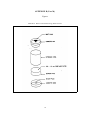
Canister
7.0
PROCEDURE
7.1
System Set-Up
1.
All connections in the vacuum system except
the canisters and manifold are sealed. All
connections, lines, and valves are checked
for leaks by pressurizing the line to 30 psig
and using a soap solution. The septum is
checked for leaks by visual inspection.
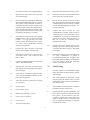
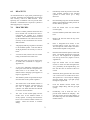
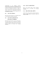
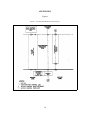
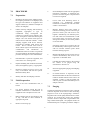
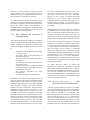
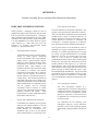
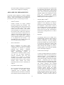
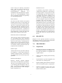
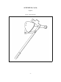
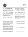
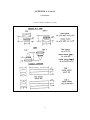
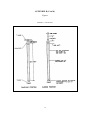
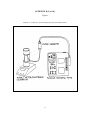
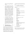
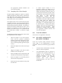
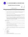
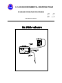
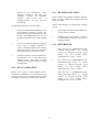
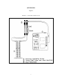
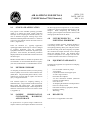
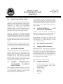
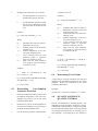
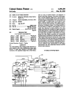
Canister Cleaning System (Figure
1, Appendix A)
2.
The liquid nitrogen is added to the cryogenic
trap and allowed to equilibrate.
Vacuum pump - capable of evacuating sample
canister(s) to an absolute pressure of <0.05 mm Hg.
3.
Check the pump to assure proper working
order by achieving a vacuum of 0.05 mm Hg
in the line that normally attaches to the
manifold but is now capped. Valve A is
open and Valve B is closed. After the
vacuum test is completed, turn the pump off
and remove the cap to break the vacuum.
4.
Check the oven to assure proper working
order by heating the oven to 100EC and
measuring the internal temperature with a
thermometer.
Cryogenic trap - stainless steel U-shaped open tubular
trap cooled with liquid nitrogen to prevent
contamination from back diffusion of oil from vacuum
pump.
5.
Check reagents to assure proper purity.
6.
Set the back pressure on the nitrogen to 30
psig.
Stainless steel two-stage pressure regulator 0-690 kPa
(0-100 psig) to regulate nitrogen pressure.
7.2
Cleaning
1.
All canisters are vented to the outside air
under an operating exhaust hood.
2.
Connect the canisters (with the valves closed
on the canisters) to the manifold by the
Swagelok fittings. Connect the manifold to
Sample canister - Leak-free stainless steel pressure
vessels at desired volume (e.g., 6L), with valve and
Summa passivated interior surfaces (Scientific
Instrumentation Specialists, Inc., P.O. Box 8941,
Moscow, ID, 83843 or Anderson Samplers, Inc.,
4215-C Wendell Dr., Atlanta, GA, 30336), or
equivalent.
5.2
Manifold - stainless steel manifold with connections
for simultaneously cleaning several canisters.
Shutoff valve(s) - two on/off toggle valves (Valves A,
and B).
Stainless steel vacuum gauge (pressure gauge) capable of measuring vacuum in the manifold to an
absolute pressure of <0.05 mm Hg or less.
Teflon tee with a septum port - an injection port
capable of introducing distilled, deionized water to
provide moisture to the nitrogen supply line.
2
the vacuum system by the Swagelok fitting.
18.
Disconnect manifold from cleaning system.
3.
Open Valve A, assure Valve B is closed, and
start vacuum pump.
19.
Disconnect canisters from the manifold and
place a brass cap on each canister.
4.
Once a vacuum (0.05 mm Hg) is obtained in
the line and the manifold, Valve A is closed.
The system is then examined for leaks by
comparing the initial vacuum reading and a
second vacuum reading three minutes later.
If the vacuum deteriorates more than 5 mm
Hg, a leak exists and corrective action, such
as tightening all fittings, is necessary.
20.
Choose the one canister of this set of four,
that was analyzed as being the most highly
contaminated previous to cleaning. Fill this
canister with ultra high purity nitrogen to a
pressure of 30 psig.
21.
Analyze the above canister for VOC
contamination by GC/MS. If this canister is
sufficiently clean to the extent that no VOC
contamination is present at concentrations
greater than 0.2 ppbv, then all canisters in
that set of four are considered clean.
Document the results.
22.
Evacuate the above canister again to 0.05
mm Hg, cap it with a brass fitting, and store
it with the other three of the lot. Document
the location.
23.
If the above canister is not sufficiently clean
(i.e. VOC contamination is present at
concentrations greater than 0.2 ppbv), then
all canisters in that lot must be cleaned again
until the canisters meet the prescribed
criteria. Document the results.
7.3
Leak-Testing
1.
Once the canister lot is determined as being
clean, the canisters are pressurized to 30 psig
with nitrogen.
2.
The initial pressure is measured via the
pressure gauge, the canister valve is closed,
and the brass cap is replaced. Document the
time and pressure.
3.
After 24 hours, the final pressure is checked.
Document the time and pressure.
4.
If leak tight, the pressure should not vary
more than ±13.8 kPa (±2 psig) over the 24hour period. If this criterion is met, the
canister is capped with a brass fitting and
stored. If a leak is present, corrective action
such as tightening all fittings, is required.
Document the results.
5.
If no leaks are observed, Valve A is opened
and the Canister 1 valve is opened. Evacuate
Canister 1 to 0.05 mm Hg, then close
Canister 1 valve. By evacuating one canister
at a time, cross contamination between
canisters is minimized.
6.
Evacuate all other canisters in the same
manner as described in the above step.
7.
After all four canisters are evacuated, open
all canister valves. Turn on the oven and
heat to 100EC.
8.
Continue evacuating canisters for one hour at
100EC. Document the time.
9.
After one hour, Valve A is closed and Valve
B is opened, with the regulator metering the
flow of nitrogen.
10.
Inject 100 µL of distilled, deionized water
via a syringe through the humidity injector
port in the nitrogen line.
11.
Allow the canisters to pressurize to 30 psig
for 15 minutes.
12.
Close Valve B.
13.
Close canister valves.
14.
Repeat steps 5 through 13, twice.
15.
Close valves on canisters.
16.
Close Valve A.
17.
Turn off vacuum pump.
3
8.0
either case, the results will be documented.
CALCULATIONS
There are no calculations for this SOP.
10.
All canisters will be leak-tested for 24 hours
and the results will be documented.
9.0
11.
All canisters will be stored evacuated and
capped with a brass fitting. The pressure and
location will be documented.
10.0
DATA VALIDATION
QUALITY
ASSURANCE/
QUALITY CONTROL
The following specific quality assurance/quality
control procedures are applicable for Summa canister
cleaning:
1.
All connections, lines, and valves are
checked to assure no leaks are present.
2.
The septum is checked, to assure no leaks are
present, by removing the septum and visually
examining it.
3.
The pump is checked to assure proper
working order by achieving a vacuum of 0.05
mm Hg prior to cleaning.
4.
The oven is checked to assure proper
working order by comparing the oven setting
at 100EC to the internal temperature with a
thermometer.
5.
This section is not applicable to this SOP.
11.0
When working with potentially hazardous materials,
follow U.S. EPA, OSHA or corporate health and
safety practices. More specifically, liquid nitrogen is
used to cool the cryogenic trap. Its boiling point is
-196EC. Insulated gloves, lab coat, face shield, and
safety glasses must be worn when using this material.
Liquid nitrogen must be transported only in properly
constructed containers.
Ultra high purity nitrogen is used to clean the
canisters and must be labeled properly. All cylinders
must be securely fastened to a stationary object. The
cylinder valve should only be opened by hand. The
proper regulator must be used and set correctly.
The reagents are checked to assure sufficient
purity.
6.
All canisters are to be evacuated to 0.05 mm
Hg during each cycle of the cleaning process
and the results are to be documented.
7.
All canisters are to be evacuated at 100EC
for one hour during each cycle of the
cleaning process.
Results are to be
documented.
8.
All canisters are to be evacuated, heated, and
pressurized three times during the cleaning
process. Document each cycle.
9.
The selected canister from the cleaning lot to
be tested must be analyzed by GC/MS as
shown to be sufficiently cleaned to the extent
that no VOC contamination is present at
concentrations greater than 0.2 ppbv for the
canister lot to be considered cleaned. If the
VOC contamination is greater than 0.2 ppbv,
the canister lot must be cleaned again. In
HEALTH AND SAFETY
The oven is set to a temperature of 100EC. Insulated
gloves should be worn when handling items heated to
this temperature.
Prior to cleaning, canisters are to be vented to the
atmosphere under an operating exhaust hood. The
hood must be in proper working order.
Canisters are pressurized during the cleaning
operation. No canister is to be pressurized above 30
psig. The maximum pressure limit for the Summa
canisters is 40 psig.
12.0
REFERENCES
ASTM Standards D1356-73A - Standard Definitions
of Terms and Relating to Atmospheric Sampling and
Analysis.
Compendium of Methods for the Determination of
Toxic Organic Compounds in Ambient Air
EPA/600/4-87/006, September 1986, Method TO-14
4
- Determination of Volatile Organic Compounds
(VOCs) in Ambient Air Using Summa Canister
Sampling and Gas Chromatographic Analysis.
5
APPENDIX A
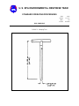
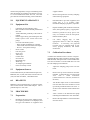
Figure
FIGURE 1. Canister Cleaning System
6
SUMMA CANISTER SAMPLING
1.0
is drawn through a sampling train comprised of
components that regulate the rate and duration of
sampling into a pre-evacuated Summa passivated
canister. Alternatively, subatmospheric pressure
sampling may be performed using a fixed orifice,
capillary, or adjustable micrometering valve in lieu of
the mass flow controller/vacuum pump arrangement
for taking grab samples or short duration
time-integrated samples. Usually, the alternative
types of flow controllers are appropriate only in
situations where screening samples are taken to assess
for future sampling activities.
SCOPE AND APPLICATION
The purpose of this standard operating procedure
(SOP) is to describe a procedure for sampling of
volatile organic compounds (VOCs) in ambient air.
The method is based on samples collected as whole
air samples in Summa passivated stainless steel
canisters. The VOCs are subsequently separated by
gas chromatography (GC) and measured by
mass-selective detector or multidetector techniques.
This method presents procedures for sampling into
canisters at final pressures both above and below
atmospheric pressure (respectively referred to as
pressurized and subatmospheric pressure sampling).
3.0
This method is applicable to specific VOCs that have
been tested and determined to be stable when stored in
pressurized and subatmospheric pressure canisters.
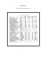
The organic compounds that have been successfully
collected in pressurized canisters by this method are
listed in the Volatile Organic Compound Data Sheet
(Appendix A). These compounds have been measured
at the parts per billion by volume (ppbv) level.
SAMPLE
PRESERVATION,
CONTAINERS,
HANDLING,
AND STORAGE
After the air sample is collected, the canister valve is
closed, an identification tag is attached to the canister,
and the canister is transported to a laboratory for
analysis. Upon receipt at the laboratory, the canister
tag data is recorded. Sample holding times and
expiration should be determined prior to initiating
field activities.
These are standard (i.e., typically applicable)
operating procedures which may be varied or changed
as required, dependent on site conditions, equipment
limitations or limitations imposed by the procedure or
other procedure limitations. In all instances, the
ultimate procedures employed should be documented
and associated with the final report.
4.0
INTERFERENCES
A ND
POTENTIAL PROBLEMS
Contamination may occur in the sampling system if
canisters are not properly cleaned before use.
Additionally, all other sampling equipment (e.g.,
pump and flow controllers) should be thoroughly
cleaned.
Mention of trade names or commercial products does
not constitute U.S. EPA endorsement or
recommendation for use.
2.0
SOP#: 1704
DATE: 07/27/95
REV. #: 0.1
5.0
METHOD SUMMARY
EQUIPMENT/APPARATUS
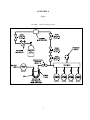
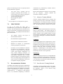
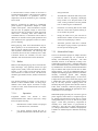
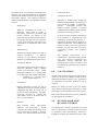
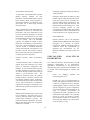
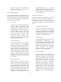
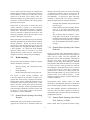
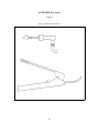
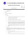
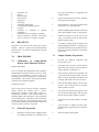
The following equipment/apparatus (Figure 1,
Appendix B) is required:
Both subatmospheric pressure and pressurized
sampling modes use an initially evacuated canister.
Both modes may also use a mass flow
controller/vacuum pump arrangement to regulate flow.
With the above configuration, a sample of ambient air
1
5.1
Subatmospheric Pressure Sampling
Equipment
1.
VOC canister sampler - whole air sampler
capable of filling an initially evacuated
canister by action of the flow controlled
pump from vacuum to near atmospheric
pressure. (Andersen Samplers Inc., Model
87-100 or equivalent).
2.
Sampling inlet line - stainless steel tubing to
connect the sampler to the sample inlet.
3.
Sample canister - leak-free stainless steel
pressure vessels of desired volume with
valve and Summa passivated interior
surfaces
(Scientific
Instrumentation
Specialist, Inc., ID 83843, Andersen
Samplers, Inc., or equivalent).
4.
5.
6.
surfaces
(Scientific
Instrumentation
Specialist, Inc., ID 83843, Andersen
Samplers, Inc., or equivalent).
Fixed orifice, capillary, or adjustable
micrometering valve - used in lieu of the
electronic flow controller/vacuum pump for
grab
samples
or
short
duration
time-integrated samples.
1.
VOC canister sampler - whole air sampler
capable of filling an initially evacuated
canister by action of the flow controlled
pump from vacuum to near atmospheric
pressure. (Andersen Samplers Inc., Model
87-100).
2.
Sampling inlet line - stainless steel tubing to
connect the sampler to the sample inlet.
3.
Sample canister - leak-free stainless steel
pressure vessels of desired volume with
valve and Summa passivated interior
5.
Chromatographic grade stainless steel tubing
and fittings - for interconnections (Alltech
Associates, Cat. #8125, or equivalent). All
materials in contact with sample, analyte,
and support gases should be chromatographic
grade stainless steel.
6.0
REAGENTS
7.0
PROCEDURE
7.1
Subatmospheric Pressure Sampling
7.1.1 Sampling Using a Fixed Orifice,
Capillary,
or
Adjustable
Micrometering Valve
Chromatographic grade stainless steel tubing
and fittings - for interconnections (Alltech
Associates, Cat. #8125, or equivalent). All
materials in contact with sample, analyte,
and support gases should be chromatographic
grade stainless steel.
Pressurized Sampling Equipment
Particulate matter filter - 2-µm sintered
stainless steel in-line filter (Nupro Co.,
Model SS-2F-K4-2, or equivalent).
This section is not applicable to this SOP.
Particulate matter filter - 2-µm sintered
stainless steel in-line filter (Nupro Co.,
Model SS-2F-K4-2, or equivalent).
5.2
4.
2
1.
Prior to sample collection, the appropriate
information is completed on the Canister
Sampling Field Data Sheet (Appendix C).
2.
A canister, which is evacuated to 0.05 mm
Hg and fitted with a flow restricting device,
is opened to the atmosphere containing the
VOCs to be sampled.
3.
The pressure differential causes the sample
to flow into the canister.
4.
This technique may be used to collect grab
samples (duration of 10 to 30 seconds) or
time-integrated samples (duration of 12 to 24
hours). The sampling duration depends on
the degree to which the flow is restricted.
5.
A critical orifice flow restrictor will have a
decrease in the flow rate as the pressure
approaches atmospheric.
6.
Upon sample completion at the location, the
appropriate information is recorded on the
Canister Sampling Field Data Sheet.
VOCs to be sampled.
7.1.2 Sampling Using a Mass Flow
Controller/Vacuum
Pump
Arrangement (Andersen Sampler
Model 87-100)
3.
A whole air sample is drawn into the system
through a stainless steel inlet tube by a direct
drive blower motor assembly.
4.
A small portion of this whole air sample is
pulled from the inlet tube by a specially
modified inert vacuum pump in conjunction
with a mass flow controller.
1.
Prior to sample collection the appropriate
information is completed on the Canister
Sampling Field Data Sheet (Appendix C).
2.
A canister, which is evacuated to 0.05 mm
Hg and connected in line with the sampler, is
opened to the atmosphere containing the
VOCs to be sampled.
5.
The initially evacuated canister is filled by
action of the flow controlled pump to a
positive pressure not to exceed 25 psig.
6.
A whole air sample is drawn into the system
through a stainless steel inlet tube by a direct
drive blower motor assembly.
A digital time-programmer is used to
pre-select sample duration and start and stop
times.
7.
Upon sample completion at the location, the
appropriate information is recorded on the
Canister Sampling Field Data Sheet.
8.0
CALCULATIONS
1.
A flow control device is chosen to maintain
a constant flow into the canister over the
desired sample period. This flow rate is
determined so the canister is filled to about
88.1 kPa for subatmospheric pressure
sampling or to about one atmosphere above
ambient pressure for pressurized sampling
over the desired sample period. The flow
rate can be calculated by:
3.
4.
A small portion of this whole air sample is
pulled from the inlet tube by a specially
modified inert vacuum pump in conjunction
with a mass flow controller.
5.
The initially evacuated canister is filled by
action of the flow controlled pump to near
atmospheric pressure.
6.
A digital time-program is used to pre-select
sample duration and start and stop times.
7.
Upon sample completion at the location, the
appropriate information is recorded on the
Canister Sampling Field Data Sheet.
7.2
F '
(P)(V)
(T)(60)
Pressurized Sampling
where:
7.2.1 Sampling Using a Mass Flow
Controller/Vacuum
P u mp
Arrangement (Anderson Sampler
Model 87-100)
1.
2.
Prior to sample commencement at the
location, the appropriate information is
completed on the Canister Sampling Field
Data Sheet.
F
P
=
=
V
=
T
=
flow rate (cm3/min)
final canister pressure,
atmospheres absolute
volume of the canister
(cm3)
sample period (hours)
For example, if a 6-L canister is to be filled to 202
kPa (two atmospheres) absolute pressure in 24 hours,
the flow rate can be calculated by:
A canister, which is evacuated to 0.05 mm
Hg and connected in line with the sampler, is
opened to the atmosphere containing the
3
F '
2.
11.0
(2)(6000)
' 8.3cm 3/min
(24)(60)
When working with potentially hazardous materials,
follow U.S. EPA, OSHA, and corporate health and
safety practices. Specifically, pressurizing of Summa
canisters should be performed in a well ventilated
room, or preferably under a fume hood. Care must be
taken not to exceed 40 psi in the canisters. Canisters
are under pressure, albeit only 20-30 psi, and should
not be dented or punctured. They should be stored in
a cool dry place and always be placed in their plastic
shipping boxes during transport and storage.
If the canister pressure is increased, a
dilution factor (DF) is calculated and
recorded on the sampling data sheet.
DF '
HEALTH AND SAFETY
Ya
Xa
where:
Xa
Ya
=
=
canister pressure (kPa,
psia) absolute before
dilution.
canister pressure (kPa,
psia)
absolute
after
dilution.
After sample analysis, detected VOC concentrations
are multiplied by the dilution factor to determine
concentration in the sampled air.
9.0
12.0
REFERENCES
1.
Ralph M. Riggin, Technical Assistance
Document for Sampling and Analysis of
Toxic Organic Compounds in Ambient Air,
EPA-600/4-83-027 U. S. Environmental
Protection Agency, Research Triangle Park,
NC, 1983.
2.
W. A. McClenny, J. D. Pleil, T. A. Lumpkin
and K. D. Oliver, "Update on Canister-Based
Samplers for VOCs," Proceedings of the
1987
EPA/APCA
Symposium
on
Measurement of Toxic and Related Air
Pollutants, May, 1987 APCA Publication
VIP-8, EPA 600/9-87-010.
3.
J. F. Walling, "The Utility of Distributed Air
Volume Sets When Sampling Ambient Air
Using Solid Adsorbents," Atmospheric
Environ., 18:855-859, 1984.
4.
J. F. Walling, J. E. Bumgarner, J. D.
Driscoll,C. M. Morris, A. E. Riley, and L. H.
Wright, "Apparent Reaction Products
Desorbed From Tenax Used to Sample
Ambient Air," Atmospheric Environ.,
20:51-57, 1986.
5.
Portable Instruments User's Manual for
Monitoring
VOC
S o u r c e s,
EPA-340/1-88-015, U.S. Environmental
Protection Agency, Office of Air Quality
Planning and Standards, Washington, D.C.,
June 1986.
QUALITY
ASSURANCE/
QUALITY CONTROL
The following general quality assurance procedures
apply:
1.
All data must be documented on standard
chain of custody records, field data sheets, or
site logbooks.
2.
All instrumentation must be operated in
accordance with operating instructions as
supplied by the manufacturer, unless
otherwise specified in the work plan.
Equipment checkout and calibration
activities
must
occur
prior
to
sampling/operation, and they must be
documented.
10.0
DATA VALIDATION
This section is not applicable to this SOP.
4
6.
R. A. Rasmussen and J. E. Lovelock,
Atmospheric Measurements Using Canister
Technology, J. Geophys. Res., 83:
8369-8378, 1983.
7.
R. A. Rasmussen and M. A. K. Khalil,
"Atmospheric Halocarbon: Measurements
and Analysis of Selected Trace Gases," Proc.
NATO ASI on Atmospheric Ozone, BO:
209-23l.
8.
5
EPA Method TO-14 "Determination of
Volatile Organic Compounds (VOC's) in
Ambient Air Using Summa Passivated
Canister Sampling and Gas Chromatographic
Analysis", May 1988.
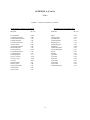
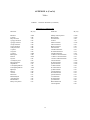
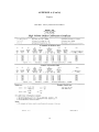
APPENDIX A
Volatile Organic Compound Data Sheet
6
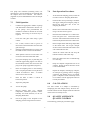
APPENDIX B
FIGURE 1. Subatmospheric/Pressurized Sampling Equipment
7
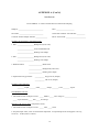
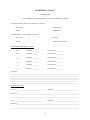
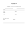
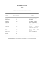
APPENDIX C
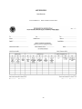
Canister Sampling Field Data Sheet
Page
of
SUMMA AIR SAMPLING WORK SHEET
Site#:
Work Assignment Manager:
Project Leader:
Site:
Samplers:
Date:
Sample #
Location
SUMMA ID
Orifice Used
Analysis/Method
Time (Start)
Time (Stop)
Total Time
SUMMA WENT TO
AMBIENT
YES/NO
YES/NO
Pressure Gauge
Pressure Gauge
Flow Rate (Pre)
Flow Rate (Post)
Flow Rate (Average)
MET Station On-site? Y / N
General Comments:
8
YES/NO
YES/NO
YES/NO
SUMMA CANISTER
FIELD STANDARDS
1.0
SOP#: 1706
DATE: 09/12/94
REV. #: 0.0
are used. In addition, the needle valve on the Summa
canister must be completely closed when not in use.
When transporting and storing, the Summa canister is
placed in a plastic shipping container. This will
protect the canister from accidental punctures or
dents.
SCOPE AND APPLICATION
The objective of this procedure is to establish standard
operating practices for the use of Summa canisters.
Summa polished canisters are used to store calibration
gas standards for transport to field sampling sites.
These standards contained in the Summa canisters
will be used for calibration of field instrumentation .
In addition, a series of different concentrations of gas
standards, or dilutions in the field of a single canister,
can be used to construct calibration curves and to
ascertain minimum detection limits on various field
instrumentation currently used by EPA/ERT.
4.0
INTERFERENCES
A ND
POTENTIAL PROBLEMS
Mention of trade names or commercial products does
not constitute U.S. EPA endorsement or
recommendation for use.
As long as the gas standards and all transfer lines are
clean, no interferences are expected. The initial
pressure of the Summa canister should be recorded
after filling. In addition, the pressure should be
recorded after each use. A dramatic drop in pressure
(i.e., five psi or more) may invalidate the use of that
canister.
2.0
5.0
EQUIPMENT/APPARATUS
C
Summa Canister, 6-liter total volume
Cat # 87-300, Anderson Samplers, Inc.
4215 Wendell Drive, Atlanta, GA 30376
PN # 0650, SIS, P.O. Box 8941, 815
Courtney St., Moscow, Idaho 83843
C
Certified gas standard from Scott Gas,
Matheson or other reliable manufacturer
C
Hamilton gas tight syringe with Teflon seal
plugs in various sizes
C
Clean Teflon tubing, 1/4" O.D.
C
Swagelok "tee" 1/4" O.D. Teflon
C
1/4" Teflon swagelok nuts & ferrules
C
9-mm septa, preferably Teflon backed
C
Swagelok on/off or needle valve, 1/4" O.D.
stainless steel
METHOD SUMMARY
A clean evacuated Summa canister is obtained. A
certified gas standard cylinder is selected and a
delivery pressure of 20-30 psi is set. The lines are
bled with the gas standard. Then, the Summa canister
is opened while still attached to the gas standard line,
and is charged to 20-30 psi with the certified gas
standard cylinder. The Summa canister is closed and
the gas standard lines are removed. A "tee" with a
septum is attached onto the Swagelok fitting of the
Summa canister. The "tee" is purged with the
contents of the Summa canister. The Summa canister
valve is opened and samples can be taken via a gas
tight syringe through the septum on the "tee". The
valve is closed when not in use. Tedlar bags can also
be filled from the "tee".
3.0
SAMPLE
PRESERVATION,
CONTAINERS,
HANDLING,
AND STORAGE
Samples and gas standards can be kept several months
in the Summa polished canisters. Care must be taken
to ensure no leaks occur when the "tee" and septu m
1
9.
All standards must be vapor phase pressurized gas
cylinders, certified by the manufacturer to be within
±2% accuracy, and to be NBS traceable. Scott
Specialty Gas or Matheson Gas can provide these
standards. If field dilution is required, a cylinder of
ultra high purity air is required.
Periodically check the pressure on the dual
stage regulator attached to the standard
cylinder to ensure 20-30 psi is being
delivered.
10.
Once the hissing stops, the canister should be
filled to approximately the same pressure as
the line delivery pressure.
7.0
PROCEDURES
11.
Close the needle valve on the Summa
canister tightly.
1.
Obtain a Summa polished canister that has
been cleaned and evacuated and select a
compressed gas cylinder of a certified
standard. This standard should be certified
by the manufacturer to be within ±2% for the
accuracy of the concentration level and be
NBS traceable.
12.
Close the standard cylinder and vent the feed
lines.
13.
Remove the feed line from the top of the
Teflon "tee".
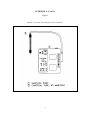
14.
Place a Swagelok back ferrule, in the
inverted position, on the top of the "tee".
This will provide a flat surface on which a
Teflon-backed septum can be placed.
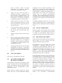
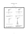
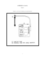
15.
Place the Teflon-backed septum, Teflon side
down. The septum should create a gas tight
fit once a 1/4" Swagelok nut is tightened
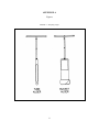
onto the top of the "tee" (Figures 3 and 4,
Appendix A).
6.0
2.
REAGENTS
A high purity dual stage regulator is attached
to the standard cylinder. This must deliver
20-30 psi pressure at an accuracy of ±10% or
better.
3.
A section of clean, unused 1/4" O.D. Teflon
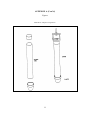
tubing is attached to the Teflon "tee".
4.
The side port of the "tee" has an on/off valve
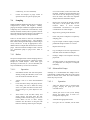
or needle valve connected to it (Figure 1,
Appendix A).
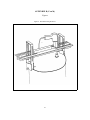
16.
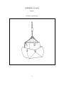
A vent line is temporally connected to the
outlet port of the side valve and placed in a
fume hood or on an outside vent. The
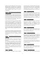
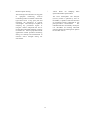
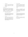
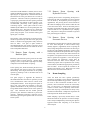
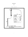
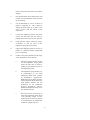
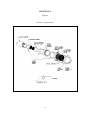
Summa canister charging system appears in
Figure 2 (Appendix A).
Open the needle valve on the Summa
canister to check for leaks throughout the
"tee", particularly in the septum fitting. Do
this with the valve on the side of the "tee"
closed.
17.
Afterwards, slowly open the side valve of the
"tee" and vent for 1/2 minute and re-close.
The septum "tee" is now ready for sampling
from the canister using a gas tight syringe
through the septum seal.
18.
Close the Summa canister needle valve
between sample taking with the gas tight
syringe.
19.
Periodically, vent or flush the "tee" to
provide fresh standard for sampling. The
side valve can also be used, after flushing, to
fill Tedlar bags with the standard from the
Summa canister.
5.
6.
The standard cylinder is opened at 20-30 psi
from the outlet of the cylinder regulator.
7.
The needle valve on the Summa canister is
still closed at this point. The side valve on
the "tee" is opened and the standard
cylinder's 1/4" Teflon feed lines are allowed
to vent for one-two minutes.
8.
The valve is then closed tightly and the
needle valve on the Summa canister is
slowly opened. A hissing noise should be
heard. Do not fill the Summa canisters too
rapidly. Allow the canister to continue
filling.
2
8.0
CALCULATIONS
10.0
The procedure for performing field dilutions of the
standards from the Summa canisters must be
documented. This allows for the recalculation of
concentrations of standards if any discrepancies arise
in the calibration of the field instrumentation. Simple
volumetric dilutions using Hamilton gas tight
syringes, are performed using Tedlar bags with ultra
high purity air as the diluent.
9.0
DATA VALIDATION
This section is not applicable to this SOP.
11.0
HEALTH AND SAFETY
Pressurizing of Summa canisters should be performed
in a well ventilated room, or preferably under a fume
hood. Care must be taken not to exceed 40 psi in the
canisters. Canisters are under pressure, albeit only
20-30 psi, and should not be dented or punctured.
They should be stored in a cool dry place and always
be placed in their plastic shipping boxes during
transport and storage.
QUALITY
ASSURANCE/
QUALTIY CONTROL
The concentration levels of the certified gas standards
must be recorded. The vendor typically provides the
analysis of certification with each standards cylinder;
a copy should be provided with the Summa canister.
12.0
REFERENCES
This section is not applicable to this SOP.
As previously stated, the pressure of the canister along
with the date and time, should be recorded at the
initial filling and at the end of each use of the canister.
A drop in pressure of 5-10 psi in between usages may
invalidate the canister for use as a calibration
standard. Certification of canister cleaning and
evacuation should be noted prior to filling with
standards.
3
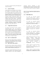
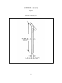
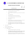
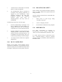
APPENDIX A
Figures
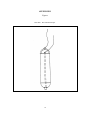
FIGURE 1. Teflon "Tee" Setup
4
APPENDIX A - (Con't)
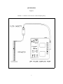
Figures
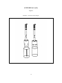
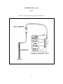
FIGURE 2. Summa Canister Charging System
5
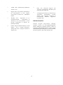
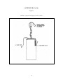
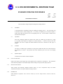
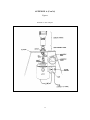
APPENDIX A - (Con’t)
Figures
FIGURE 3. Septum "Tee" Setup
6
APPENDIX A - (Con't)
Figures
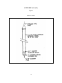
FIGURE 4. Teflon Nut with Septum
7
GENERAL FIELD
SAMPLING GUIDELINES
1.0
material under investigation.
SCOPE AND APPLICATION
The extent to which valid inferences can be drawn
from a sample depends on the degree to which the
sampling effort conforms to the project's objectives.
For example, as few as one sample may produce
adequate, technically valid data to address the
project's objectives. Meeting the project's objectives
requires thorough planning of sampling activities, and
implementation of the most appropriate sampling and
analytical procedures. These issues will be discussed
in this procedure.
The purpose of this Standard Operating Procedure
(SOP) is to provide general field sampling guidelines
that will assist REAC personnel in choosing sampling
strategies, location, and frequency for proper
assessment of site characteristics. This SOP is
applicable to all field activities that involve sampling.
These are standard (i.e., typically applicable)
operating procedures which may be varied or changed
as required, dependent on site conditions, equipment
limitations or limitations imposed by the procedure. In
all instances, the ultimate procedures employed should
be documented and associated with the final report.
3.0
Mention of trade names or commercial products does
not constitute U.S. EPA endorsement or
recommendation for use.
2.0
SOP#: 2001
DATE: 08/11/94
REV. #: 0.0
SAMPLE
PRESERVATION,
CONTAINERS,
HANDLING,
AND STORAGE
The amount of sample to be collected, and the proper
sample container type (i.e., glass, plastic), chemical
preservation, and storage requirements are dependent
on the matrix being sampled and the parameter(s) of
interest. Sample preservation, containers, handling,
and storage for air and waste samples are discussed in
the specific SOPs for air and waste sampling
techniques.
METHOD SUMMARY
Sampling is the selection of a representative portion of
a larger population, universe, or body. Through
examination of a sample, the characteristics of the
larger body from which the sample was drawn can be
inferred. In this manner, sampling can be a valuable
tool for determining the presence, type, and extent of
contamination by hazardous substances in the
environment.
4.0
INTERFERENCES
AND
POTENTIAL PROBLEMS
The nature of the object or materials being sampled
may be a potential problem to the sampler. If a
material is homogeneous, it will generally have a
uniform composition throughout. In this case, any
sample increment can be considered representative of
the material. On the other hand, heterogeneous
samples present problems to the sampler because of
changes in the material over distance, both laterally
and vertically.
The primary objective of all sampling activities is to
characterize a hazardous waste site accurately so that
its impact on human health and the environment can
be properly evaluated. It is only through sampling and
analysis that site hazards can be measured and the job
of cleanup and restoration can be accomplished
effectively with minimal risk. The sampling itself
must be conducted so that every sample collected
retains its original physical form and chemical
composition. In this way, sample integrity is insured,
quality assurance standards are maintained, and the
sample can accurately represent the larger body of
Samples of hazardous materials may pose a safety
threat to both field and laboratory personnel. Proper
health and safety precautions should be implemented
when handling this type of sample.
1
Environmental conditions, weather conditions, or
non-target chemicals may cause problems and/or
interferences when performing sampling activities or
when sampling for a specific parameter. Refer to the
specific SOPs for sampling techniques.
5.0
The importance of making the distinction between
environmental and hazardous samples is two-fold:
Personnel safety requirements: Any sample
thought to contain enough hazardous
materials to pose a safety threat should be
designated as hazardous and handled in a
manner which ensures the safety of both field
and laboratory personnel.
(2)
Transportation requirements: Hazardous
samples must be packaged, labeled, and
shipped according to the International Air
Transport Association (IATA) Dangerous
Goods Regulations or Department of
Transportation (DOT) regulations and U.S.
EPA guidelines.
7.2
Sample Collection Techniques
EQUIPMENT/APPARATUS
The equipment/apparatus required to collect samples
must be determined on a site specific basis. Due to the
wide variety of sampling equipment available, refer to
the specific SOPs for sampling techniques which
include lists of the equipment/apparatus required for
sampling.
6.0
(1)
REAGENTS
Reagents may be utilized for preservation of samples
and for decontamination of sampling equipment. The
preservatives required are specified by the analysis to
be performed.
Decontamination solutions are
specified in ERT SOP #2006, Sampling Equipment
Decontamination.
7.0
PROCEDURE
7.1
Types of Samples
In general, two basic types of sample collection
techniques are recognized, both of which can be used
for either environmental or hazardous samples.
Grab Samples
A grab sample is defined as a discrete aliquot
representative of a specific location at a given point in
time. The sample is collected all at once at one
particular point in the sample medium.
The
representativeness of such samples is defined by the
nature of the materials being sampled. In general, as
sources vary over time and distance, the
representativeness of grab samples will decrease.
In relation to the media to be sampled, two basic types
of samples can be considered: the environmental
sample and the hazardous sample.
Environmental samples are those collected from
streams, ponds, lakes, wells, and are off-site samples
that are not expected to be contaminated with
hazardous materials. They usually do not require the
special handling procedures typically used for
concentrated wastes. However, in certain instances,
environmental samples can contain elevated
concentrations of pollutants and in such cases would
have to be handled as hazardous samples.
Composite Samples
Composites are nondiscrete samples composed of
more than one specific aliquot collected at various
sampling locations and/or different points in time.
Analysis of this type of sample produces an average
value and can in certain instances be used as an
alternative to analyzing a number of individual grab
samples and calculating an average value. It should
be noted, however, that compositing can mask
problems by diluting isolated concentrations of some
hazardous compounds below detection limits.
Hazardous or concentrated samples are those collected
from drums, tanks, lagoons, pits, waste piles, fresh
spills, or areas previously identified as contaminated,
and require special handling procedures because of
their potential toxicity or hazard. These samples can
be further subdivided based on their degree of hazard;
however, care should be taken when handling and
shipping any wastes believed to be concentrated
regardless of the degree.
Compositing is often used for environmental samples
and may be used for hazardous samples under certain
conditions. For example, compositing of hazardous
waste is often performed after compatibility tests have
2
been completed to determine an average value over a
number of different locations (group of drums). This
procedure generates data that can be useful by
providing an average concentration within a number
of units, can serve to keep analytical costs down, and
can provide information useful to transporters and
waste disposal operations.
C
concentration),
and
basis
of
the
information/data.
Technical approach including media/matrix
to be sampled, sampling equipment to be
used, sample equipment decontamination (if
necessary), sampling design and rationale,
and SOPs or description of the procedure to
be implemented.
Project management and reporting, schedule,
project organization and responsibilities,
manpower and cost projections, and required
deliverables.
QA objectives and protocols including tables
summarizing field sampling and QA/QC
analysis and objectives.
For sampling situations involving hazardous wastes,
grab sampling techniques are generally preferred
because grab sampling minimizes the amount of time
sampling personnel must be in contact with the
wastes, reduces risks associated with compositing
unknowns, and eliminates chemical changes that
might occur due to compositing.
C
7.3
Note that this list of QAWP components is not allinclusive and that additional elements may be added
or altered depending on the specific requirements of
the field investigation. It should also be recognized
that although a detailed QAWP is quite important, it
may be impractical in some instances. Emergency
responses and accidental spills are prime examples of
such instances where time might prohibit the
development of site-specific QAWPs prior to field
activities. In such cases, investigators would have to
rely on general guidelines and personal judgment, and
the sampling or response plans might simply be a
strategy based on preliminary information and
finalized on site. In any event, a plan of action should
be developed, no matter how concise or informal, to
aid investigators in maintaining a logical and
consistent order to the implementation of their task.
C
Types of Sampling Strategies
The number of samples that should be collected and
analyzed depends on the objective of the investigation.
There are three basic sampling strategies: random,
systematic, and judgmental sampling.
Random sampling involves collection of samples in a
nonsystematic fashion from the entire site or a specific
portion of a site. Systematic sampling involves
collection of samples based on a grid or a pattern
which has been previously established. When
judgmental sampling is performed, samples are
collected only from the portion(s) of the site most
likely to be contaminated. Often, a combination of
these strategies is the best approach depending on the
type of the suspected/known contamination, the
uniformity and size of the site, the level/type of
information desired, etc.
7.4
7.5
The data derived from sampling activities are often
introduced as critical evidence during litigation of a
hazardous waste site cleanup. Legal issues in which
sampling data are important may include cleanup cost
recovery, identification of pollution sources and
responsible parties, and technical validation of
remedial design methodologies. Because of the
potential for involvement in legal actions, strict
adherence to technical and administrative SOPs is
essential during both the development and
implementation of sampling activities.
QA Work Plans (QAWP)
A QAWP is required when it becomes evident that a
field investigation is necessary. It should be initiated
in conjunction with, or immediately following,
notification of the field investigation. This plan should
be clear and concise and should detail the following
basic components, with regard to sampling activities:
C
C
C
C
Legal Implications
Objective and purpose of the investigation.
Basis upon which data will be evaluated.
Information known about the site including
location, type and size of the facility, and
length of operations/abandonment.
Type and volume of contaminated material,
contaminants of concern (including
Technically valid sampling begins with thorough
planning and continues through the sample collection
and analytical procedures.
Administrative
requirements
involve
thorough,
accurate
3
documentation
of
all
sampling
activities.
Documentation requirements include maintenance of
a chain of custody, as well as accurate records of field
activities and analytical instructions. Failure to
observe these procedures fully and consistently may
result in data that are questionable, invalid and
non-defensible in court, and the consequent loss of
enforcement proceedings.
Refer to the specific SOPs for data validation
activities that are associated with sampling
techniques.
8.0
When working with potentially hazardous materials,
follow U.S. EPA, OSHA, and corporate health and
safety procedures.
10.0
11.0
CALCULATIONS
Refer to the specific SOPs for any calculations which
are associated with sampling techniques.
9.0
QUALITY ASSURANCE/
QUALITY CONTROL
Refer to the specific SOPs for the type and frequency
of QA/QC samples to be analyzed, the acceptance
criteria for the QA/QC samples, and any other QA/QC
activities which are associated with sampling
techniques.
4
DATA VALIDATION
HEALTH AND SAFETY
SAMPLING EQUIPMENT
DECONTAMINATION
1.0
water wash to facilitate residuals removal. The
second step involves a tap water rinse and a
distilled/deionized water rinse to remove the
detergent. An acid rinse provides a low pH media for
trace metals removal and is included in the
decontamination process if metal samples are to be
collected. It is followed by another distilled/deionized
water rinse. If sample analysis does not include
metals, the acid rinse step can be omitted. Next, a
high purity solvent rinse is performed for trace
organics removal if organics are a concern at the site.
Typical solvents used for removal of organic
contaminants include acetone, hexane, or water.
Acetone is typically chosen because it is an excellent
solvent, miscible in water, and not a target analyte on
the Priority Pollutant List. If acetone is known to be
a contaminant of concern at a given site or if Target
Compound List analysis (which includes acetone) is
to be performed, another solvent may be substituted.
The solvent must be allowed to evaporate completely
and then a final distilled/deionized water rinse is
performed. This rinse removes any residual traces of
the solvent.
SCOPE AND APPLICATION
The purpose of this Standard Operating Procedure
(SOP) is to provide a description of the methods used
for
preventing,
minimizing,
or
limiting
cross-contamination of samples due to inappropriate
or inadequate equipment decontamination and to
provide general guidelines for developing
decontamination procedures for sampling equipment
to be used during hazardous waste operations as per
29 Code of Federal Regulations (CFR) 1910.120.
This
SOP
does
not
address
personnel
decontamination.
These are standard (i.e. typically applicable) operating
procedures which may be varied or changed as
required, dependent upon site conditions, equipment
limitation, or limitations imposed by the procedure.
In all instances, the ultimate procedures employe d
should be documented and associated with the final
report.
Mention of trade names or commercial products does
not constitute U.S. Environmental Protection Agency
(U.S. EPA) endorsement or recommendation for use.
2.0
SOP#: 2006
DATE: 08/11/94
REV. #: 0.0
The decontamination procedure described above may
be summarized as follows:
METHOD SUMMARY
1.
2.
3.
4.
5.
6.
7.
8.
9.
Removing or neutralizing contaminants from
equipment minimizes the likelihood of sample cross
contamination, reduces or eliminates transfer of
contaminants to clean areas, and prevents the mixing
of incompatible substances.
Gross contamination can be removed by physical
decontamination procedures. These abrasive and
non-abrasive methods include the use of brushes, air
and wet blasting, and high and low pressure water
cleaning.
Physical removal
Non-phosphate detergent wash
Tap water rinse
Distilled/deionized water rinse
10% nitric acid rinse
Distilled/deionized water rinse
Solvent rinse (pesticide grade)
Air dry
Distilled/deionized water rinse
If a particular contaminant fraction is not present at
the site, the nine (9) step decontamination procedure
specified above may be modified for site specificity.
For example, the nitric acid rinse may be eliminate d
if metals are not of concern at a site. Similarly, th e
solvent rinse may be eliminated if organics are not of
The first step, a soap and water wash, removes all
visible particulate matter and residual oils and grease.
This may be preceded by a steam or high pressure
1
concern at a site. Modifications to the standard
procedure should be documented in the site specific
work plan or subsequent report.
3.0
bristle scrub brushes or long-handled bottle brushes
can be used to remove contaminants.
Large
galvanized wash tubs, stock tanks, or buckets can hold
wash and rinse solutions. Children's wading pools can
also be used. Large plastic garbage cans or other
similar containers lined with plastic bags can help
segregate contaminated equipment. Contaminated
liquid can be stored temporarily in metal or plastic
cans or drums.
SAMPLE
PRESERVATION,
CONTAINERS,
HANDLING,
AND STORAGE
The amount of sample to be collected and the proper
sample container type (i.e., glass, plastic), chemical
preservation, and storage requirements are dependent
on the matrix being sampled and the parameter(s) o f
interest.
More specifically, sample collection and analysis o f
decontamination waste may be required before
beginning proper disposal of decontamination liquids
and solids generated at a site. This should be
determined prior to initiation of site activities.
4.0
INTERFERENCES
AND
POTENTIAL PROBLEMS
C
The use of distilled/deionized water
commonly available from commercial
vendors
may
be
acceptable
for
decontamination of sampling equipment
provided that it has been verified by
laboratory analysis to be analyte free
(specifically for the contaminants of
concern).
C
The use of an untreated potable water supply
is not an acceptable substitute for tap water.
Tap water may be used from any municipal
or industrial water treatment system.
C
The following standard materials and equipment ar e
recommended for decontamination activities:
Damage can be incurred by acid and solvent
washing of complex and sophisticated
sampling equipment.
5.0
EQUIPMENT/APPARATUS
Decontamination Solutions
C
C
C
C
Non-phosphate detergent
Selected solvents (acetone, hexane, nitric
acid, etc.)
Tap water
Distilled or deionized water
5.2
Decontamination Tools/Supplies
C
C
C
C
C
C
C
C
Long and short handled brushes
Bottle brushes
Drop cloth/plastic sheeting
Paper towels
Plastic or galvanized tubs or buckets
Pressurized sprayers (H 2O)
Solvent sprayers
Aluminum foil
5.3
Health and Safety Equipment
Appropriate personal protective equipment (i.e., safety
glasses or splash shield, appropriate gloves, aprons or
coveralls, respirator, emergency eye wash)
If acids or solvents are utilized in
decontamination they raise health and safety,
and waste disposal concerns.
C
5.1
Decontamination equipment, materials, and supplies
are generally selected based on availability. Othe r
considerations include the ease of decontaminating or
disposing of the equipment. Most equipment and
supplies can be easily procured. For example, soft-
5.4
Waste Disposal
C
C
C
C
Trash bags
Trash containers
55-gallon drums
Metal/plastic buckets/containers for storage
and disposal of decontamination solutions
6.0
REAGENTS
There are no reagents used in this procedure aside
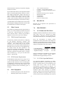
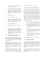
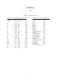
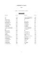
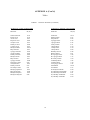
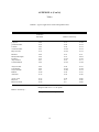
from the actual decontamination solutions. Table 1
(Appendix A) lists solvent rinses which may be
required for elimination of particular chemicals. In
2
general, the following solvents are typically utilized
for decontamination purposes:
contaminants by neutralization, chemical reaction,
disinfection, or sterilization.
C
Physical decontamination techniques can be grouped
into two categories:
abrasive methods and
non-abrasive methods, as follows:
10% nitric acid is typically used for
inorganic compounds such as metals. An
acid rinse may not be required if inorganics
are not a contaminant of concern.
Acetone (pesticide grade) (1)
Hexane (pesticide grade) (1)
Methanol(1)
C
C
C
(1)
7.1.1 Abrasive Cleaning Methods
Abrasive cleaning methods work by rubbing and
wearing away the top layer of the surface containing
the contaminant. The mechanical abrasive cleanin g
methods are most commonly used at hazardous waste
sites. The following abrasive methods are available:
- Only if sample is to be analyzed for organics.
7.0
PROCEDURES
As part of the health and safety plan, a
decontamination plan should be developed and
reviewed. The decontamination line should be set up
before any personnel or equipment enter the areas of
potential exposure. The equipment decontamination
plan should include:
Mechanical
C
The number, location, and layout of
decontamination stations.
Mechanical methods of decontamination include using
metal or nylon brushes. The amount and type of
contaminants removed will vary with the hardness of
bristles, length of time brushed, degree of brush
contact, degree of contamination, nature of the surface
being cleaned, and degree of contaminant adherence
to the surface.
C
Decontamination equipment needed.
Air Blasting
C
Appropriate decontamination methods.
C
Methods for disposal of contaminated
clothing, equipment, and solutions.
C
Procedures can be established to minimize
the potential for contamination. This may
include: (1) work practices that minimize
contact with potential contaminants; (2)
using remote sampling techniques; (3)
covering monitoring and sampling equipment
with plastic, aluminum foil, or other
protective material; (4) watering down dusty
areas; (5) avoiding laying down equipment in
areas of obvious contamination; and (6) use
of disposable sampling equipment.
Air blasting equipment uses compressed air to force
abrasive material through a nozzle at high velocities.
The distance between nozzle and surface cleaned, air
pressure, time of application, and angle at which the
abrasive strikes the surface will dictate cleaning
efficiency. Disadvantages of this method are the
inability to control the amount of material removed
and the large amount of waste generated.
7.1
Wet Blasting
Wet blast cleaning involves use of a suspended fine
abrasive. The abrasive/water mixture is delivered by
compressed air to the contaminated area. By using a
very fine abrasive, the amount of materials removed
can be carefully controlled.
Decontamination Methods
7.1.2 Non-Abrasive Cleaning Methods
All samples and equipment leaving the contaminated
area of a site must be decontaminated to remove any
contamination that may have adhered to equipment.
Various decontamination methods will remove
contaminants by: (1) flushing or other physical
action, or (2) chemical complexing to inactivate
Non-abrasive cleaning methods work by forcing the
contaminant off a surface with pressure. In general,
the equipment surface is not removed using
non-abrasive methods.
3
Low-Pressure Water
7.2
This method consists of a container which is filled
with water. The user pumps air out of the container to
create a vacuum. A slender nozzle and hose allow the
user to spray in hard-to-reach places.
Field
Sampling
Equipment
Decontamination Procedures
The decontamination line is setup so that the first
station is used to clean the most contaminated item.
It progresses to the last station where the least
contaminated item is cleaned. The spread of
contaminants is further reduced by separating each
decontamination station by a minimum of three (3)
feet. Ideally, the contamination should decrease as the
equipment progresses from one station to another
farther along in the line.
High-Pressure Water
This method consists of a high-pressure pump, an
operator controlled directional nozzle, and a highpressure hose. Operating pressure usually ranges
from 340 to 680 atmospheres (atm) and flow rates
usually range from 20 to 140 liters per minute.
Damp Cloth Removal
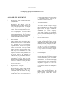
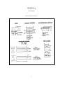
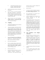
A site is typically divided up into the following
boundaries: Hot Zone or Exclusion Zone (EZ), the
Contamination Reduction Zone (CRZ), and the
Support or Safe Zone (SZ). The decontamination line
should be setup in the Contamination Reduction
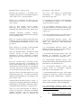
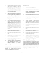
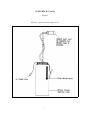
Corridor (CRC) which is in the CRZ. Figure 1
(Appendix B) shows a typical contaminant reduction
zone layout. The CRC controls access into and out of
the exclusion zone and confines decontamination
activities to a limited area. The CRC boundaries
should be conspicuously marked. The far end is the
hotline, the boundary between the exclusion zone and
the contamination reduction zone. The size of the
decontamination corridor depends on the number of
stations in the decontamination process, overall
dimensions of the work zones, and amount of space
available at the site. Whenever possible, it should be
a straight line.
In some instances, due to sensitive, non-waterproof
equipment or due to the unlikelihood of equipment
being contaminated, it is not necessary to conduct an
extensive decontamination procedure. For example,
air sampling pumps hooked on a fence, placed on a
drum, or wrapped in plastic bags are not likely to
become heavily contaminated. A damp cloth should
be used to wipe off contaminants which may have
adhered to equipment through airborne contaminants
or from surfaces upon which the equipment was set .
Anyone in the CRC should be wearing the level of
protection designated for the decontamination crew.
Another corridor may be required for the entry and
exit of heavy equipment. Sampling and monitoring
equipment and sampling supplies are all maintained
outside of the CRC. Personnel don their equipment
away from the CRC and enter the exclusion zone
through a separate access control point at the hotline.
One person (or more) dedicated to decontaminating
equipment is recommended.
Ultra-High-Pressure Water
This system produces a water jet that is pressured
from 1,000 to 4,000 atmospheres.
This
ultra-high-pressure spray can remove tightly-adhered
surface films. The water velocity ranges from 500
meters/second (m/s) (1,000 atm) to 900 m/s (4,000
atm). Additives can be used to enhance the cleaning
action.
Rinsing
Contaminants are removed by rinsing through
dilution, physical attraction, and solubilization.
Disinfection/Sterilization
7.2.1 Decontamination Setup
Disinfectants are a practical means of inactivating
infectious agents.
Unfortunately, standard
sterilization methods are impractical for large
equipment. This method of decontamination is
typically performed off-site.
Starting with the most contaminated station, the
decontamination setup should be as follows:
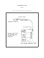
Station 1: Segregate Equipment Drop
Place plastic sheeting on the ground (Figure 2,
Appendix B). Size will depend on amount of
4
equipment to be decontaminated. Provide containers
lined with plastic if equipment is to be segregated.
Segregation may be required if sensitive equipment or
mildly contaminated equipment is used at the same
time as equipment which is likely to be heavily
contaminated.
pool with tap water. Several bottle and bristle brushes
should be dedicated to this station. Approximately
10-50 gallons of water may be required initially
depending upon the amount of equipment to
decontaminate and the amount of gross contamination.
Station 5: Low-Pressure Sprayers
Station 2: Physical Removal With A High-Pressure
Washer (Optional)
Fill a low-pressure sprayer with distilled/deionize d
water. Provide a 5-gallon bucket or basin to contain
the water during the rinsing process. Approximately
10-20 gallons of water may be required initially
depending upon the amount of equipment to
decontaminate and the amount of gross contamination.
As indicated in 7.1.2, a high-pressure wash may be
required for compounds which are difficult to remove
by washing with brushes. The elevated temperature of
the water from the high-pressure washers is excellent
at removing greasy/oily compounds. High pressur e
washers require water and electricity.
Station 6: Nitric Acid Sprayers
A decontamination pad may be required for the highpressure wash area. An example of a wash pad may
consist of an approximately 1 1/2 foot-deep basin
lined with plastic sheeting and sloped to a sump at one
corner. A layer of sand can be placed over the plastic
and the basin is filled with gravel or shell. The sump
is also lined with visqueen and a barrel is placed in the
hole to prevent collapse. A sump pump is used to
remove the water from the sump for transfer into a
drum.
Fill a spray bottle with 10% nitric acid. An acid rinse
may not be required if inorganics are not a
contaminant of concern. The amount of acid will
depend on the amount of equipment to be
decontaminated. Provide a 5-gallon bucket or basin to
collect acid during the rinsing process.
Station 7: Low-Pressure Sprayers
Fill a low-pressure sprayer with distilled/deionize d
water. Provide a 5-gallon bucket or basin to collect
water during the rinsate process.
Typically heavy machinery is decontaminated at the
end of the day unless site sampling requires that the
machinery be decontaminated frequently. A separate
decontamination pad may be required for heavy
equipment.
Station 8: Organic Solvent Sprayers
Fill a spray bottle with an organic solvent. After each
solvent rinse, the equipment should be rinsed with
distilled/deionized water and air dried. Amount of
solvent will depend on the amount of equipment to
decontaminate. Provide a 5-gallon bucket or basin to
collect the solvent during the rinsing process.
Station 3: Physical Removal With Brushes And A
Wash Basin
Prior to setting up Station 3, place plastic sheeting on
the ground to cover areas under Station 3 through
Station 10.
Fill a wash basin, a large bucket, or child's swimming
pool with non-phosphate detergent and tap water.
Several bottle and bristle brushes to physically remove
contamination should be dedicated to this station .
Approximately 10 - 50 gallons of water may be
required initially depending upon the amount of
equipment to decontaminate and the amount of gross
contamination.
Solvent rinses may not be required unless organics are
a contaminant of concern, and may be eliminated from
the station sequence.
Station 9: Low-Pressure Sprayers
Fill a low-pressure sprayer with distilled/deionize d
water. Provide a 5-gallon bucket or basin to collect
water during the rinsate process.
Station 4: Water Basin
Station 10: Clean Equipment Drop
Fill a wash basin, a large bucket, or child's swimming
Lay a clean piece of plastic sheeting over the bottom
5
plastic layer. This will allow easy removal of the
plastic in the event that it becomes dirty. Provide
aluminum foil, plastic, or other protective material to
wrap clean equipment.
Using a spray bottle rinse sampling equipment with
nitric acid. Begin spraying (inside and outside) at one
end of the equipment allowing the acid to drip to the
other end into a 5-gallon bucket. A rinsate blank may
be required at this station. Refer to Section 9.
7.2.2 Decontamination Procedures
Station 7: Low-Pressure Sprayers
Station 1: Segregate Equipment Drop
Rinse sampling equipment with distilled/deionized
water with a low-pressure sprayer.
Deposit equipment used on-site (i.e., tools, sampling
devices and containers, monitoring instruments radios,
clipboards, etc.) on the plastic drop cloth/sheet or in
different containers with plastic liners. Each will be
contaminated to a different degree. Segregation at the
drop reduces the probability of cross contamination .
Loose leaf sampling data sheets or maps can be placed
in plastic zip lock bags if contamination is evident.
Station 8: Organic Solvent Sprayers
Rinse sampling equipment with a solvent. Begin
spraying (inside and outside) at one end of the
equipment allowing the solvent to drip to the other
end into a 5-gallon bucket. Allow the solvent to
evaporate from the equipment before going to the next
station. A QC rinsate sample may be required at this
station.
Station 2: Physical Removal With A High-Pressure
Washer (Optional)
Station 9: Low-Pressure Sprayers
Use high pressure wash on grossly contaminated
equipment. Do not use high- pressure wash on
sensitive or non-waterproof equipment.
Rinse sampling equipment with distilled/deionized
water with a low-pressure washer.
Station 3: Physical Removal With Brushes And A
Wash Basin
Station 10 : Clean Equipment Drop
Lay clean equipment on plastic sheeting. Once ai r
dried, wrap sampling equipment with aluminum foil,
plastic, or other protective material.
Scrub equipment with soap and water using bottle and
bristle brushes. Only sensitive equipment (i.e., radios,
air monitoring and sampling equipment) which is
waterproof should be washed. Equipment which is
not waterproof should have plastic bags removed and
wiped down with a damp cloth. Acids and organic
rinses may also ruin sensitive equipment. Consult the
manufacturers for recommended decontamination
solutions.
7.2.3 Post Decontamination Procedures
1.
Collect high-pressure pad and heavy
equipment decontamination area liquid and
waste and store in appropriate drum or
container. A sump pump can aid in the
collection process. Refer to the Department
of Transportation (DOT) requirements for
appropriate containers based on the
contaminant of concern.
2.
Collect high-pressure pad and heavy
equipment decontamination area solid waste
and store in appropriate drum or container.
Refer to the DOT requirements for
appropriate containers based on the
contaminant of concern.
3.
Empty soap and water liquid wastes from
basins and buckets and store in appropriate
Station 4: Equipment Rinse
Wash soap off of equipment with water by immersing
the equipment in the water while brushing. Repeat as
many times as necessary.
Station 5: Low-Pressure Rinse
Rinse sampling equipment with distilled/deionized
water with a low-pressure sprayer.
Station 6: Nitric Acid Sprayers ( required only if
metals are a contaminant of concern)
6
drum or container. Refer to the DOT
requirements for appropriate containers
based on the contaminant of concern.
4.
Empty acid rinse waste and place in
appropriate container or neutralize with a
base and place in appropriate drum. pH
paper or an equivalent pH test is required for
neutralization. Consult DOT requirements
for appropriate drum for acid rinse waste.
equipment to test for residual contamination. The
blank water is collected in sample containers for
handling, shipment, and analysis. These samples are
treated identical to samples collected that day. A
rinsate blank is used to assess cross contamination
brought about by improper decontamination
procedures. Where dedicated sampling equipment is
not utilized, collect one rinsate blank per day per type
of sampling device samples to meet QA2 and QA 3
objectives.
5.
Empty solvent rinse sprayer and solvent
waste into an appropriate container. Consult
DOT requirements for appropriate drum for
solvent rinse waste.
If sampling equipment requires the use of plastic
tubing it should be disposed of as contaminated and
replaced with clean tubing before additional sampling
occurs.
6.
Using low-pressure sprayers, rinse basins,
and brushes. Place liquid generated from
this process into the wash water rinse
container.
10.0
7.
Empty low-pressure sprayer water onto the
ground.
8.
Place all solid waste materials generated
from the decontamination area (i.e., gloves
and plastic sheeting, etc.) in an approved
DOT drum. Refer to the DOT requirements
for appropriate containers based on the
contaminant of concern.
9.
Write appropriate labels for waste and make
arrangements for disposal. Consult DOT
regulations for the appropriate label for each
drum generated from the decontamination
process.
8.0
CALCULATIONS
DATA VALIDATION
Results of quality control samples will be evaluated
for contamination. This information will be utilize d
to qualify the environmental sample results in
accordance with the project's data quality objectives.
11.0
HEALTH AND SAFETY
When working with potentially hazardous materials ,
follow OSHA, U.S. EPA, corporate, and other
applicable health and safety procedures.
Decontamination can pose hazards under certain
circumstances.
Hazardous substances may be
incompatible with decontamination materials. For
example, the decontamination solution may react with
contaminants to produce heat, explosion, or toxic
products.
Also, vapors from decontamination
solutions may pose a direct health hazard to workers
by inhalation, contact, fire, or explosion.
A rinsate blank is one specific type of quality control
sample associated with the field decontamination
process. This sample will provide information on the
effectiveness of the decontamination process
employed in the field.
The decontamination solutions must be determined to
be acceptable before use. Decontamination materials
may degrade protective clothing or equipment; some
solvents can permeate protective clothing.
If
decontamination materials do pose a health hazard,
measures should be taken to protect personnel or
substitutions should be made to eliminate the hazard.
The choice of respiratory protection based on
contaminants of concern from the site may not be
appropriate for solvents used in the decontamination
process.
Rinsate blanks are samples obtained by running
analyte free water over decontaminated sampling
Safety considerations should be addressed when using
abrasive
and
non-abrasive
decontamination
This section is not applicable to this SOP.
9.0
QUALITYASSURANCE/
QUALITY CONTROL
7
equipment. Maximum air pressure produced by
abrasive equipment could cause physical injury.
Displaced material requires control mechanisms.
12.0
REFERENCES
Field Sampling Procedures Manual, New Jersey
Department of Environmental Protection, February,
1988.
Material generated from decontamination activities
requires proper handling, storage, and disposal.
Personal Protective Equipment may be required for
these activities.
A Compendium of Superfund Field Operations
Methods, EPA 540/p-87/001.
Material safety data sheets are required for all
decontamination solvents or solutions as required by
the Hazard Communication Standard (i.e., acetone ,
alcohol, and trisodiumphosphate).
Engineering Support Branch Standard Operating
Procedures and Quality Assurance Manual, USEPA
Region IV, April 1, 1986.
In some jurisdictions, phosphate containing detergents
(i.e., TSP) are banned.
Guidelines for the Selection of Chemical Protective
Clothing, Volume 1, Third Edition, American
Conference of Governmental Industrial Hygienists,
Inc., February, 1987.
Occupational Safety and Health Guidance Manual for
Hazardous
Waste
Site
Activities,
NIOSH/OSHA/USCG/EPA, October, 1985.
8
APPENDIX A
Table
Table 1. Soluble Contaminants and Recommended Solvent Rinse
TABLE 1
Soluble Contaminants and Recommended Solvent Rinse
SOLVENT (1)
EXAMPLES OF
SOLVENTS
SOLUBLE
CONTAMINANTS
Water
Deionized water
Tap water
Low-chain hydrocarbons
Inorganic compounds
Salts
Some organic acids and other polar
compounds
Dilute Acids
Nitric acid
Acetic acid
Boric acid
Basic (caustic) compounds (e.g., amines
and hydrazines)
Dilute Bases
Sodium bicarbonate (e.g.,
soap detergent)
Acidic compounds
Phenol
Thiols
Some nitro and sulfonic compounds
Alcohols
Ethers
Ketones
Aromatics
Straight chain alkalines
(e.g.,
hexane)
Common petroleum
products
(e.g., fuel, oil,
kerosene)
Nonpolar compounds (e.g., some
organic compounds)
Hexane
PCBs
Organic Solvents
(2)
Organic Solvent (2)
(1)
-
Material safety data sheets are required for all decontamination solvents or solutions as required
by the Hazard Communication Standard
(2)
-
WARNING: Some organic solvents can permeate and/or degrade the protective clothing
9
APPENDIX B
Figures
Figure 1. Contamination Reduction Zone Layout
10
APPENDIX B (Cont’d.)
Figures
Figure 2. Decontamination Layout
11
GROUNDWATER WELL
SAMPLING
1.0
and need not be the same as the device used for
purging. Care should be taken when choosing the
sampling device as some will affect the integrity of
the sample. Sampling should occur in a progression
from the least to most contaminated well, if this
information is known.
SCOPE AND APPLICATION
The objective of this standard operating procedure
(SOP) is to provide general reference information on
sampling of ground water wells. This guideline is
primarily concerned with the collection of water
samples from the saturated zone of the subsurface.
Every effort must be made to ensure that the sample
is representative of the particular zone of water being
sampled. These procedures are designed to be used in
conjunction with analyses for the most common types
of ground water contaminants (e.g., volatile and semivolatile organic compounds, pesticides, metals,
biological parameters).
The growing concern over the past several years over
low levels of volatile organic compounds in water
supplies has led to the development of highly
sophisticated analytical methods that can provide
detection limits at part per trillion levels. While the
laboratory methods are extremely sensitive, well
controlled and quality assured, they cannot
compensate for a poorly collected sample. The
collection of a sample should be as sensitive, highly
developed and quality assured as the analytical
procedures.
These are standard (i.e., typically applicable)
operating procedures which may be varied or changed
as required, dependent upon site conditions,
equipment limitations or limitations imposed by the
procedure. In all instances, the ultimate procedures
employed should be documented and associated with
the final report.
3.0
Mention of trade names or commercial products does
not constitute U.S. Environmental Protection Agency
(EPA) endorsement or recommendation for use.
2.0
SOP#: 2007
DATE: 01/26/95
REV. #: 0.0
SAMPLE
PRESERVATION,
CONTAINERS,
HANDLING,
AND STORAGE
The type of analysis for which a sample is being
collected determines the type of bottle, preservative,
holding time, and filtering requirements. Samples
should be collected directly from the sampling device
into appropriate laboratory cleaned containers. Check
that a Teflon liner is present in the cap, if required.
Attach a sample identification label. Complete a field
data sheet, a chain of custody form, and record all
pertinent data in the site logbook.
METHOD SUMMARY
In order to obtain a representative groundwater sample
for chemical analysis it is important to remove
stagnant water in the well casing and the water
immediately adjacent to the well before collection of
the sample. This may be achieved with one of a
number of instruments. The most common of these
are the bailer, submersible pump, non-contact gas
bladder pump, inertia pump and suction pump. At a
minimum, three well volumes should be purged, if
possible. Equipment must be decontaminated prior to
use and between wells. Once purging is completed
and the correct laboratory-cleaned sample containers
have been prepared, sampling may proceed. Sampling
may be conducted with any of the above instruments,
Samples shall be appropriately preserved, labelled,
logged, and placed in a cooler to be maintained at
4EC. Samples must be shipped well before the
holding time is up and ideally should be shipped
within 24 hours of sample collection. It is imperative
that samples be shipped or delivered daily to the
analytical laboratory in order to maximize the time
available for the laboratory to perform the analyses.
The bottles should be shipped with adequate packing
and cooling to ensure that they arrive intact.
1
Sample retrieval systems suitable for the valid
collection of volatile organic samples are: positive
displacement bladder pumps, gear driven submersible
pumps, syringe samplers and bailers (Barcelona, 1984;
Nielsen, 1985). Field conditions and other constraints
will limit the choice of appropriate systems. The
focus of concern must remain to provide a valid
sample for analysis, one which has been subjected to
the least amount of turbulence possible.
4.2
In a nonpumping well, there will be little or no
vertical mixing of the water, and stratification will
occur. The well water in the screened section will
mix with the ground water due to normal flow
patterns, but the well water above the screened section
will remain isolated, become stagnant, and may lack
the contaminants representative of the ground water.
Persons sampling should realize that stagnant water
may contain foreign material inadvertently or
deliberately introduced from the surface, resulting in
an unrepresentative sample. To safeguard against
collecting nonrepresentative stagnant water, the
following guidelines and techniques should be
adhered to during sampling:
Treatment of the sample with sodium thiosulfate
preservative is required only if there is residual
chlorine in the water that could cause free radical
chlorination and change the identity of the original
contaminants. It should not be used if there is no
chlorine in the water.
Holding time for volatiles analysis is seven days. It is
imperative that the sample be shipped or delivered
daily to the analytical laboratory. The bottles must be
shipped on their sides to aid in maintaining the airtight
seal during shipment, with adequate packing and
cooling to ensure that they arrive intact.
For collection of volatile organic samples, refer to the
work plan to ensure that 40 mL glass sample vials
with Teflon lined septa are ordered and in sufficient
numbers. Check sampling supplies; field kit for
chlorine, preservatives, Parafilm, foam sleeves and
coolers. Due to the extreme trace levels at which
volatile organics are detectable, cross contamination
and introduction of contaminants must be avoided.
Trip blanks are incorporated into the shipment
package to provide a check against cross
contamination.
4.0
INTERFERENCES
AND
POTENTIAL PROBLEMS
4.1
General
Purging
The primary goal in performing ground water
sampling is to obtain a representative sample of the
ground water body. Analysis can be compromised by
field personnel in two primary ways: (1) taking an
unrepresentative sample, or (2) by incorrect handling
of the sample. There are numerous ways of
introducing foreign contaminants into a sample, and
these must be avoided by following strict sampling
procedures and utilizing trained field personnel.
2
1.
As a general rule, all monitor wells should be
pumped or bailed prior to sampling. Purge
water should be containerized on site or
handled as specified in the site specific
project plan. Evacuation of a minimum of
one volume of water in the well casing, and
preferably three to five volumes, is
recommended for a representative sample.
In a high-yielding ground water formation
and where there is no stagnant water in the
well above the screened section, evacuation
prior to sample withdrawal is not as critical.
However, in all cases where the monitoring
data is to be used for enforcement actions,
evacuation is recommended.
2.
When purging with a pump (not a bailer), the
pump should be set at the screened interval,
or if the well is an open-rock well, it should
be set at the same depth the sample will be
collected. When sampling a screened well,
the sample should also be collected from the
same depth the pump was set at.
3.
The well should be sampled as soon as
possible after purging.
4.
Analytical parameters typically dictate
whether the sample should be collected
through the purging device, or through a
separate sampling instrument.
5.
For wells that can be pumped or bailed to
dryness with the equipment being used, the
well should be evacuated and allowed to
recover prior to collecting a sample. If the
recovery rate is fairly rapid and time allows,
evacuation of more than one volume of water
is preferred. If recovery is slow, sample the
well upon recovery after one evacuation.
6.
4.3
Advantages
A non-representative sample can also result
from excessive pre-pumping of the
monitoring well.
Stratification of the
leachate concentration in the ground water
formation may occur, or heavier-than-water
compounds may sink to the lower portions of
the aquifer. Excessive pumping can dilute or
increase the contaminant concentrations from
what is representative of the sampling point
of interest.
Materials
Materials of construction for samplers and evacuation
equipment (bladders, pump, bailers, tubing, etc.)
should be limited to stainless steel, TeflonR, and glass
in areas where concentrations are expected to be at or
near the detection limit. The tendency of organics to
leach into and out of many materials make the
selection of materials critical for trace analyses. The
use of plastics, such as PVC or polyethylene, should
be avoided when analyzing for organics. However,
PVC may be used for evacuation equipment as it will
not come in contact with the sample, and in highly
contaminated wells, disposable equipment (i.e.,
polypropylene bailers) may be appropriate to avoid
cross-contamination.
Advantages/Disadvantages
Certain Equipment
Only practical limitations on size and
materials
C
No power source needed
C
Portable
C
Inexpensive, so it can be dedicated and hung
in a well, thereby reducing the chances of
cross contamination
C
Minimal outgassing of volatile organics
while sample is in bailer
C
Readily available
C
Removes stagnant water first
C
Rapid, simple method for removing small
volumes of purge water
Disadvantages
Materials of construction (bladders/ pumps, bailers,
tubing, etc.) suitable for collecting and handling
Volatile Organic Samples should be limited to
stainless steel, Teflon and glass in areas which
detection limit range concentrations are expected.
The tendency of organics to leach into and out of
many materials, make the selection of materials
critical for these trace analyses. The use of plastics,
e.g., PVC etc., should be avoided. There are
numerous ways of introducing foreign contaminants
into a sample, and these must be avoided by following
strict sampling procedures and utlization of trained
personnel.
4.4
C
C
Time-consuming to flush a large well of
stagnant water
C
Transfer of sample may cause aeration
C
Stoppers at the bottom of the bailer usually
leak thus the bailer must be brought to the
surface rapidly
C
If the bailer is allowed to hit the bottom of
the well boring, gravel can displace the ball
valve not allowing the bailer to hold water
4.4.2 Submersible Pumps
Advantages
of
4.4.1 Bailers
3
C
Portable and can be transported to several
wells
C
Depending upon the size of the pump and the
pumping depths, relatively high pumping
rates are possible
C
Generally very reliable and does not require
priming
C
Restricted to areas with water levels within
20 to 25 feet of the ground surface
Potential for effects on analysis of trace
organics
C
Vacuum can cause loss of dissolved gasses
and volatile organics
Heavy and cumbersome to deal with,
particularly in deeper wells
C
Pump must be primed and vacuum is often
difficult to maintain during initial stages of
pumping
Disadvantages
C
C
C
Expensive
C
Power source needed
4.4.5 Inertia Pumps
C
Sediment in water may cause problems with
the pumps
Advantages
C
Impractical in low yielding or shallow wells
C
Portable, inexpensive, and readily available
C
Offers a rapid method for purging relatively
shallow wells
4.4.3 Non-Contact Gas Bladder Pumps
Advantages
Disadvantages
C
Maintains integrity of sample
C
Restricted to areas with water levels within
70 feet of the ground surface
C
Easy to use
C
C
Can sample from discrete locations within
the monitor well
May be time consuming to purge wells with
these manual pumps
C
Labor intensive
C
WaTerra pumps are only effective in 2-inch
diameter wells
5.0
EQUIPMENT APPARATUS
5.1
Equipment Checklist
Disadvantages
C
Difficulty in cleaning, though dedicated
tubing and bladder may be used
C
Only useful to about 100 feet
C
Supply of gas for operation, gas bottles
and/or compressors are often difficult to
obtain and are cumbersome
C
Relatively low pumping rates
C
Requires air compressor or pressurized gas
source and control box
5.1.1 General
C
4.4.4 Suction Pumps
C
C
C
C
Advantages
C
Portable, inexpensive, and readily available
C
C
C
Disadvantages
4
Water level indicator
- electric sounder
- steel tape
- transducer
- reflection sounder
- airline
Depth sounder
Appropriate keys for well cap locks
Steel brush
HNU or OVA (whichever is
appropriate)
Logbook
Calculator
Field data sheets and samples labels
most
C
C
C
C
C
C
C
C
C
C
C
C
C
C
C
C
C
C
C
C
C
C
C
C
Chain of custody records and seals
Sample containers
Engineer's rule
Sharp knife (locking blade)
Tool box (to include at least: screwdrivers,
pliers, hacksaw, hammer, flashlight,
adjustable wrench)
Leather work gloves
Appropriate Health & Safety gear
5-gallon pail
Plastic sheeting
Shipping containers
Packing materials
Bolt cutters
Ziploc plastic bags
Containers for evacuation liquids
Decontamination solutions
Tap water
Non phosphate soap
Several brushes
Pails or tubs
Aluminum foil
Garden sprayer
Preservatives
Distilled or deionized water
Fire extinguisher (if using a generator for
your power source)
C
C
C
C
C
5.1.4 Non-Gas Contact Bladder Pump
C
C
C
C
C
C
C
C
C
C
C
C
Non-gas contact bladder pump
Compressor or nitrogen gas tank
Batteries and charger
Teflon tubing - enough to dedicate to each
well
Swagelock fitting
Toolbox supplements - same as submersible
pump
Control box (if necessary)
5.1.5 Suction Pump
C
C
5.1.2 Bailers
C
- wire strippers
- electrical tape
- heat shrink
- hose connectors
- Teflon tape
Winch, pulley or hoist
Gasoline for generator/gas can
Flow meter with gate valve
1" nipples and various plumbing (i.e., pipe
connectors)
Control box (if necessary)
C
C
C
C
Clean, decontaminated bailers of appropriate
size and construction material
Nylon line, enough to dedicate to each well
Teflon coated bailer wire
Sharp knife
Aluminum foil (to wrap clean bailers)
Five gallon bucket
Pump
1" black PVC coil tubing - enough to
dedicate to each well
Gasoline - if required
Toolbox
Plumbing fittings
Flow meter with gate valve
5.1.6 Inertia Pump
C
5.1.3 Submersible Pump
C
Pump assembly (WaTerra pump, piston
pump)
Five gallon bucket
C
C
6.0
REAGENTS
C
C
C
C
Pump(s)
Generator (110, 120, or 240 volt) or 12 volt
battery if inaccessible to field vehicle - amp
meter is useful
1" black PVC coil tubing - enough to
dedicate to each well
Hose clamps
Safety cable
Tool box supplement
- pipe wrenches
Reagents may be utilized for preservation of samples
and for decontamination of sampling equipment. The
preservatives required are specified by the analysis to
be performed.
Decontamination solutions are
specified in ERT SOP #2006, Sampling Equipment
Decontamination.
5
7.0
PROCEDURE
7.1
Preparation
1.
Determine the extent of the sampling effort,
the sampling methods to be employed, and
the types and amounts of equipment and
supplies needed (i.e, diameter and depth of
wells to be sampled).
2.
Obtain necessary sampling and monitoring
equipment, appropriate to type of
contaminant being investigated. For
collection of volatile organic samples, refer
to the work plan to ensure that 40 mL glass
sample vials with Teflon lined septa are
ordered and in sufficient numbers. Check
sampling supplies; field kit for chlorine,
preservatives, Parafilm, foam sleeves and
coolers. Due to extreme trace levels at
which volatile organics are detectable, cross
contamination
and
introduction
of
contaminants must be avoided. Trip blanks
are incorporated into the shipment package to
provide a check against cross contamination.
3.
Prepare scheduling and coordinate with staff,
clients, and regulatory agency, if appropriate.
5.
Perform a general site survey prior to site
entry in accordance with the site specific
Health and Safety Plan.
6.
Identify and mark all sampling locations.
7.2
Field Preparation
1.
Start at the least contaminated well, if
known.
2.
Lay plastic sheeting around the well to
minimize likelihood of contamination of
equipment from soil adjacent to the well.
3.
Remove locking well cap, note location, time
of day, and date in field notebook or
appropriate log form.
4.
Remove well casing cap.
Screen headspace of well with an appropriate
monitoring instrument to determine the
presence of volatile organic compounds and
record in site logbook.
6.
Lower water level measuring device or
equivalent (i.e., permanently installed
transducers or airline) into well until water
surface is encountered.
7.
Measure distance from water surface to
reference measuring point on well casing or
protective barrier post and record in site
logbook. Alternatively, if no reference point,
note that water level measurement is from
top of steel casing, top of PVC riser pipe,
from ground surface, or some other position
on the well head.
If floating organics are of concern, this can
be determined by measuring the water level
with an oil/water interface probe which
measures floating organics.
Decontaminate or preclean equipment, and
ensure that it is in working order.
4.
5.
8.
Measure total depth of well (at least twice to
confirm measurement) and record in site
logbook or on field data sheet.
9.
Calculate the volume of water in the well and
the volume to be purged using the
calculations in Section 8.0.
10.
Select the appropriate purging and sampling
equipment.
11.
If residual chlorine is suspected, use the
Hach Field Test Kit for chlorine to determine
if there is residual chlorine in the water to be
sampled. If there is, treat the sample vial
with a crystal of sodium thiosulfate prior to
sample collection.
7.3
Purging
The amount of flushing a well receives prior to sample
collection depends on the intent of the monitoring
program as well as the hydrogeologic conditions.
Programs where overall quality determination of water
resources are involved may require long pumping
periods to obtain a sample that is representative of a
large volume of that aquifer. The pumped volume can
be determined prior to sampling so that the sample is
6
a collected after a known volume of the water is
evacuated from the aquifer, or the well can be pumped
until the stabilization of parameters such as
temperature, electrical conductance, pH, or turbidity
has occurred.
foreign materials.
However, monitoring for defining a contaminant
plume requires a representative sample of a small
volume of the aquifer. These circumstances require
that the well be pumped enough to remove the
stagnant water but not enough to induce flow from
other areas. Generally, three well volumes are
considered effective, or calculations can be made to
determine, on the basis of the aquifer parameters and
well dimensions, the appropriate volume to remove
prior to sampling.
During purging, water level measurements may be
taken regularly at 15-30 second intervals. This data
may be used to compute aquifer transmissivity and
other hydraulic characteristics. The following well
evacuation devices are most commonly used. Other
evacuation devices are available, but have been
omitted in this discussion due to their limited use.
Attach the line to the bailer and slowly lower
until the bailer is completely submerged,
being careful not to drop the bailer to the
water, causing turbulence and the possible
loss of volatile organic contaminants.
4.
Pull bailer out ensuring that the line either
falls onto a clean area of plastic sheeting or
never touches the ground.
5.
Empty the bailer into a pail until full to
determine the number of bails necessary to
achieve the required purge volume.
6.
Thereafter, pour the water into a container
and dispose of purge waters as specified in
the site specific sampling plan.
7.3.2 Submersible Pumps
The use of submersible pumps for sample collection
is permissible provided they are constructed of
suitably noncontaminating materials. The chief
drawback, however, is the difficulty avoiding crosscontamination between wells. Although some units
can be disassembled easily to allow surfaces contacted
by contaminants to be cleaned, field decontamination
may be difficult and require solvents that can affect
sample analysis. The use of submersible pumps in
multiple well-sampling programs, therefore, should be
carefully considered against other sampling
mechanisms (bailers, bladder pumps). In most cases,
a sample can be collected by bailer after purging with
a submersible pump, however, submersible pumps
may be the only practical sampling device for
extremely deep wells (greater than 300 feet of water).
Under those conditions, dedicated pump systems
should be installed to eliminate the potential for crosscontamination of well samples.
7.3.1 Bailers
Bailers are the simplest purging device used and have
many advantages. They generally consist of a rigid
length of tube, usually with a ball check-valve at the
bottom. A line is used to lower the bailer into the
well and retrieve a volume of water. The three most
common types of bailer are PVC, Teflon, and stainless
steel.
This manual method of purging is best suited to
shallow or narrow diameter wells. For deep, larger
diameter wells which require evacuation of large
volumes of water, other mechanical devices may be
more appropriate.
7.3.1.1
3.
Operation
Submersible pumps generally use one of two types of
power supplies, either electric or compressed gas or
air. Electric powered pumps can run off a 12 volt DC
rechargeable battery, or a 110 or 220 volt AC power
supply. Those units powered by compressed air
normally use a small electric or gas-powered air
compressor. They may also utilize compressed gas
(i.e., nitrogen) from bottles. Different size pumps are
available for different depth or diameter monitoring
wells.
Equipment needed will include a clean
decontaminated bailer, Teflon or nylon line, a sharp
knife, and plastic sheeting.
1.
Determine the volume of water to be purged
as described in 8.0, calculations.
2.
Lay plastic sheeting around the well to
prevent contamination of the bailer line with
7
7.3.2.1
1.
2.
Determine the volume of water to be purged
as described in 8.0 Calculations.
3.
Lay plastic sheeting around the well to
prevent contamination of pumps, hoses or
lines with foreign materials.
7.3.4 Suction Pumps
3.
Assemble pump, hoses and safety cable, and
lower the pump into the well. Make sure the
pump is deep enough so all the water is not
evacuated. (Running the pump without water
may cause damage.)
4.
Attach flow meter to the outlet hose to
measure the volume of water purged.
5.
Use a ground fault circuit interrupter (GFCI)
or ground the generator to avoid possible
electric shock.
6.
7.
the same as for a submersible pump (Section
7.3.2.1).
Operation
There are many different types of suction pumps.
They include: centrifugal, peristaltic and diaphragm.
Diaphragm pumps can be used for well evacuation at
a fast pumping rate and sampling at a low pumping
rate. The peristaltic pump is a low volume pump that
uses rollers to squeeze the flexible tubing thereby
creating suction. This tubing can be dedicated to a
well to prevent cross contamination. Peristaltic
pumps, however, require a power source.
7.3.4.1
Attach power supply, and purge the well
until the specified volume of water has been
evacuated (or until field parameters, such as
temperature, pH, conductivity, etc, have
stabilized). Do not allow the pump to run
dry. If the pumping rate exceeds the well
recharge rate, lower the pump further into the
well, and continue pumping.
1.
Assembly of the pump, tubing, and power
source if necessary.
2.
Procedure for purging with a suction pump is
exactly the same as for a submersible pump
(Section 7.3.2.1).
Inertia pumps such as the WaTerra pump and piston
pump, are manually operated. They are most
appropriate to use when wells are too deep to bail by
hand, or too shallow or narrow (or inaccessible) to
warrant an automatic (submersible, etc.) pump. These
pumps are made of plastic and may be either
decontaminated or discarded.
Collect and dispose of purge waters as
specified in the site specific sampling plan.
For this procedure, an all stainless-steel and Teflon
Middleburg-squeeze bladder pump (e.g., IEA,
TIMCO, Well Wizard, Geoguard, and others) is used
to provide the least amount of material interference to
the sample (Barcelona, 1985). Water comes into
contact with the inside of the bladder (Teflon) and the
sample tubing, also Teflon, that may be dedicated to
each well. Some wells may have permanently
installed bladder pumps, (i.e., Well Wizard,
Geoguard), that will be used to sample for all
parameters.
7.3.5.1
Assemble Teflon tubing, pump and charged
control box.
2.
Procedure for purging with a bladder pump is
8
Operation
1.
Determine the volume of water to be purged
as described in 8.0, Calculations.
2.
Lay plastic sheeting around the well to
prevent contamination of pumps or hoses
with foreign materials.
3.
Assemble pump and lower to the appropriate
depth in the well.
4.
Begin pumping manually, discharging water
into a 5 gallon bucket (or other graduated
vessel). Purge until specified volume of
water has been evacuated (or until field
parameters such as temperature, pH,
Operation
1.
Operation
7.3.5 Inertia Pumps
7.3.3 Non-Contact Gas Bladder Pumps
7.3.3.1
Be sure to adjust flow rate to prevent violent
jolting of the hose as sample is drawn in.
conductivity, etc. have stabilized).
5.
Collect and dispose of purge waters as
specified in the site specific project plan.
7.4
Sampling
once at the surface, remove the bailer from
the cable. Carefully open the GPI bailer unit
and remove the vial. Begin slowly pouring
from the bailer, and collect the duplicate
samples from the midstream sample.
5.
Remove the cap from the sample container
and place it on the plastic sheet or in a
location
where
it
won't
become
contaminated. See Section 7.7 for special
considerations on VOA samples.
6.
Begin slowly pouring from the bailer.
7.
Filter and preserve samples as required by
sampling plan.
8.
Cap the sample container tightly and place
prelabeled sample container in a carrier.
9.
Replace the well cap.
10.
Log all samples in the site logbook and on
field data sheets and label all samples.
11.
The positive-displacement volatile sampling bailer is
perhaps the most appropriate for collection of water
samples for volatile analysis. Other bailer types
(messenger, bottom fill, etc.) are less desirable, but
may be mandated by cost and site conditions.
Package samples and complete necessary
paperwork.
12.
Transport sample to decontamination zone
for preparation for transport to analytical
laboratory.
7.4.1.1
7.4.2 Submersible Pumps
Sample withdrawal methods require the use of pumps,
compressed air, bailers, and samplers. Ideally,
purging and sample withdrawal equipment should be
completely inert, economical to manufacture, easily
cleaned, sterilized, reusable, able to operate at remote
sites in the absence of power resources, and capable of
delivering variable rates for sample collection.
There are several factors to take into consideration
when choosing a sampling device. Care should be
taken when reviewing the advantages or disadvantages
of any one device. It may be appropriate to use a
different device to sample than that which was used to
purge. The most common example of this is the use
of a submersible pump to purge and a bailer to
sample.
7.4.1 Bailers
Operation
1.
Surround the monitor well with clean plastic
sheeting. If using the GPI bailer, insert a vial
into the claim and assemble the unit.
2.
Attach a line to a clean decontaminated
bailer.
Lower the bailer slowly and gently into the
well, taking care not to shake the casing
sides or to splash the bailer into the water.
Stop lowering at a point adjacent to the
screen.
3.
4.
Although it is recommended that samples not be
collected with a submersible pump due to the reasons
stated in Section 4.4.2, there are some situations
where they may be used.
7.4.2.1
Allow bailer to fill and then slowly and
gently retrieve the bailer from the well
avoiding contact with the casing, so as not to
knock flakes of rust or other foreign
materials into the bailer. If using the GPI
bailer for collecting volatile organic samples,
9
Operation
1.
Allow the monitor well to recharge after
purging, keeping the pump just above
screened section.
2.
Attach gate valve to hose (if not already
fitted), and reduce flow of water to a
manageable sampling rate.
3.
Assemble the appropriate bottles.
4.
If no gate valve is available, run the water
down the side of a clean jar and fill the
sample bottles from the jar.
5.
prelabeled sample container in a carrier.
Cap the sample container tightly and place
prelabeled sample container in a carrier.
6.
Replace the well cap.
7.
Log all samples in the site logbook and on
the field data sheets and label all samples.
8.
Package samples and complete necessary
paperwork.
9.
Transport sample to decontamination zone
for preparation for transport to the analytical
laboratory.
10.
Upon completion, remove pump and
assembly and fully decontaminate prior to
setting into the next sample well. Dedicate
the tubing to the hole.
5.
Replace the well cap.
6.
Log all samples in the site logbook and on
field data sheets and label all samples.
7.
Package samples and complete necessary
paperwork.
8.
Transport sample to decontamination zone
for preparation for transport to analytical
laboratory.
9.
On completion, remove the tubing from the
well and either replace the Teflon tubing and
bladder with new dedicated tubing and
bladder or rigorously decontaminate the
existing materials.
10.
Nonfiltered samples shall be collected
directly from the outlet tubing into the
sample bottle.
11.
For filtered samples, connect the pump outlet
tubing directly to the filter unit. The pump
pressure should remain decreased so that the
pressure build up on the filter does not blow
out the pump bladder or displace the filter.
For the Geotech barrel filter, no actual
connections are necessary so this is not a
concern.
7.4.3 Non-Contact Gas Bladder Pumps
The use of a non-contact gas positive displacement
bladder pump is often mandated by the use of
dedicated pumps installed in wells. These pumps are
also suitable for shallow (less than 100 feet) wells.
They are somewhat difficult to clean, but may be used
with dedicated sample tubing to avoid cleaning.
These pumps require a power supply and a
compressed gas supply (or compressor). They may be
operated at variable flow and pressure rates making
them ideal for both purging and sampling.
7.4.4 Suction Pumps
In view of the limitations of these type pumps, they
are not recommended for sampling purposes.
Barcelona (1984) and Nielsen (1985) report that the
non-contact gas positive displacement pumps cause
the least amount of alteration in sample integrity as
compared to other sample retrieval methods.
7.4.3.1
7.4.5 Inertia Pumps
Inertia pumps may be used to collect samples. It is
more common, however, to purge with these pumps
and sample with a bailer (Section 7.4.1).
Operation
1.
Allow well to recharge after purging.
2.
Assemble the appropriate bottles.
1.
3.
Turn pump on, increase the cycle time and
reduce the pressure to the minimum that will
allow the sample to come to the surface.
Following well evacuation, allow the well to
recharge.
2.
Assemble the appropriate bottles.
Cap the sample container tightly and place
3.
Since these pumps are manually operated,
7.4.5.1
4.
10
Operation
the flow rate may be regulated by the
sampler. The sample may be discharged
from the pump outlet directly into the
appropriate sample container.
4.
Cap the sample container tightly and place
prelabeled sample container in a carrier.
5.
Replace the well cap.
6.
Log all samples in the site logbook and on
field data sheets and label all samples.
7.
Package samples and complete necessary
paperwork.
8.
Transport sample to decontamination zone
for preparation for transport to the analytical
laboratory.
9.
Upon completion, remove pump and
decontaminate or discard, as appropriate.
7.5
For samples requiring filtering, such as total metals
analysis, the filter must be decontaminated prior to
and between uses. Filters work by two methods. A
barrel filter such as the "Geotech" filter works with a
bicycle pump, used to build up positive pressure in the
chamber containing the sample which is then forced
through the filter paper (minimum size 0.45 µm) into
a jar placed underneath. The barrel itself is filled
manually from the bailer or directly via the hose of the
sampling pump. The pressure must be maintained up
to 30 lbs/in2 by periodic pumping.
A vacuum type filter involves two chambers; the
upper chamber contains the sample and a filter
(minimum size 0.45 µm) divides the chambers. Using
a hand pump or a Gilian type pump, air is withdrawn
from the lower chamber, creating a vacuum and thus
causing the sample to move through the filter into the
lower chamber where it is drained into a sample jar.
Repeated pumping may be required to drain all the
sample into the lower chamber. If preservation of the
sample is necessary, this should be done after
filtering.
7.4.6. Sample Retrieval - Syringe
A limited number of commercial syringe type
samplers are available, (IEA, TIMCO, etc.) some are
homemade devices. These devices are claimed to
provide good quality samples for volatile analysis, but
are severly limited in sample volume and are specific
to sampling for volatiles. Essentially, they operated
with an evacuated chamber that is lowered down the
well, and allowed to fill with the pressure of the
water. The entire mechanism is then brought to the
surface with the sample. The sample may then be
transferred to a sample vial, or the entire unit may be
sent as the sample container.
1.
2.
3.
Filtering
7.6
Post Operation
After all samples are collected and preserved, the
sampling equipment should be decontaminated prior
to
sampling
another
well
to
prevent
cross-contamination of equipment and monitor wells
between locations.
Evacuate the syringe if necessary, and lower
the sampling device to just below the well
screen.
Remove the constriction from the device and
allow the sample to fill the syringe, apply
slight suction as necessary.
Bring unit to the surface. If necessary,
transfer the sample to vials, as outlined in
steps 2 through 7 above.
1.
Decontaminate all equipment.
2.
Replace sampling equipment in storage
containers.
3.
Prepare and transport ground water samples
to the laboratory.
Check sample
documentation and make sure samples are
properly packed for shipment.
7.7
Special Considerations for VOA
Sampling
The proper collection of a sample for volatile organics
requires minimal disturbance of the sample to limit
volatilization and therefore a loss of volatiles from the
sample.
11
Sample retrieval systems suitable for the valid
collection of volatile organic samples are: positive
displacement bladder pumps, gear driven submersible
pumps, syringe samplers and bailers (Barcelona, 1984;
Nielsen, 1985). Field conditions and other constraints
will limit the choice of appropriate systems. The
focus of concern must be to provide a valid sample for
analysis, one which has been subjected to the least
amount of turbulence possible.
where:
n
r
h
=
=
=
The following procedures should be followed:
cf
=
1.
Open the vial, set cap in a clean place, and
collect the sample during the middle of the
cycle. When collecting duplicates, collect
both samples at the same time.
2.
Monitor well diameters are typically 2", 3", 4", or 6".
Knowing the diameter of the monitor well, there are
a number of standard conversion factors which can be
used to simplify the equation above.
Fill the vial to just overflowing. Do not rinse
the vial, nor excessively overflow it. There
should be a convex meniscus on the top of
the vial.
3.
The volume, in gallons per linear foot, for various
standard monitor well diameters can be calculated as
follows:
Check that the cap has not been
contaminated (splashed) and carefully cap
the vial. Place the cap directly over the top
and screw down firmly. Do not overtighten
and break the cap.
4.
v(gal/ft) ' nr 2 (cf)
n
r
cf
Remember that if you have a 2" diameter well, you
must convert this to the radius in feet to be able to use
the equation.
The conversion factors for the common size monitor
wells are as follows:
CALCULATIONS
Well diameter
2"
3"
4"
6"
Volume (gal/ft.) 0.1632 0.3672 0.6528 1.4688
If it is necessary to calculate the volume of the well,
utilize the following equation:
Well volume ' nr 2h (cf)
pi
radius of monitoring well (feet)
conversion factor (7.48 gal/ft3)
vol/linear ft ' nr 2 (cf)
[Equation 2]
' 3.14 (1/12 ft)2 7.48 gal/ft 3
' 0.1632 gal/ft
The holding time for VOAs is seven days.
Samples should be shipped or delivered to
the laboratory daily so as not to exceed the
holding time. Ensure that the samples
remain at 4EC, but do not allow them to
freeze.
8.0
=
=
=
For a 2" diameter well, the volume per linear foot can
be calculated as follows:
Immediately place the vial in the protective
foam sleeve and place into the cooler,
oriented so that it is lying on its side, not
straight up.
6.
[Equation 2]
where:
Invert the vial and tap gently. Observe vial
for at least ten (10) seconds. If an air bubble
appears, discard the sample and begin again.
It is imperative that no entrapped air is in the
sample vial.
5.
pi
radius of monitoring well (feet)
height of the water column (feet)
[This may be determined by
subtracting the depth to water from
the total depth of the well as
measured from the same reference
point.]
conversion factor (gal/ft3) = 7.48
gal/ft3 [In this equation, 7.48 gal/ft3
is the necessary conversion factor.]
If you utilize the conversion factors above, Equation
[Equation 1]
12
1 should be modified as follows:
Well volume ' (h)(cf)
must be implemented prior to sampling the first well.
The site health and safety plan should be reviewed
with specific emphasis placed on the protection
program planned for the well sampling tasks.
Standard safe operating practices should be followed
such as minimizing contact with potential
contaminants in both the vapor phase and liquid
matrix through the use of respirators and disposable
clothing.
[Equation 3]
where:
h
cf
=
=
height of water column (feet)
the conversion factor calculated
from Equation 2
When working around volatile organic contaminants:
The well volume is typically tripled to determine the
volume to be purged.
9.0
QUALITY ASSURANCE/
QUALITY CONTROL
There are no specific quality assurance (QA) activities
which apply to the implementation of these
procedures. However, the following general QA
procedures apply:
1.
2.
3.
All data must be documented on field data
sheets or within site logbooks.
1.
Avoid breathing constituents venting from
the well.
2.
Pre-survey the well head-space with an
FID/PID prior to sampling.
3.
If monitoring results indicate organic
constituents, sampling activities may be
conducted in Level C protection. At a
minimum, skin protection will be afforded by
disposable protective clothing.
Physical hazards associated with well sampling:
All instrumentation must be operated in
accordance with operating instructions as
supplied by the manufacturer, unless
otherwise specified in the work plan.
Equipment checkout and calibration
activities
must
occur
prior
to
sampling/operation and they must be
documented.
1.
Lifting injuries associated with pump and
bailers retrieval; moving equipment.
2.
Use of pocket knives for cutting discharge
hose.
3.
The collection of rinsate blanks is
recommended to evaluate potential for cross
contamination from the purging and/or
sampling equipment.
Heat/cold stress as a result of exposure to
extreme temperatures and protective
clothing.
4.
Slip, trip, fall conditions as a result of pump
discharge.
5.
Restricted mobility due to the wearing of
protective clothing.
6.
Electrical shock associated with use of
submersible pumps is possible. Use a GFCI
or a copper grounding stake to avoid this
problem.
12.0
REFERENCES
4.
Trip blanks are required if analytical
parameters include VOAs.
10.0
DATA VALIDATION
This section is not applicable to this SOP.
11.0
HEALTH AND SAFETY
When working with potentially hazardous materials,
follow U.S. EPA, OSHA or REAC health and safety
guidelines. More specifically, depending upon the site
specific contaminants, various protective programs
Barcelona, M.J., Helfrich, J.A., Garske, E.E., and J.P.
Gibb, Spring 1984. "A Laboratory Evaluation of
Groundwater Sampling Mechanisms," Groundwater
13
Monitoring Review, 1984 pp. 32-41.
Development. 1980, Ada, OK.
Barcelona, M.J., Helfrich, J.A., and Garske, E.E.,
"Sampling Tubing Effects on Groundwater Samples",
Analy. Chem., Vol. 57, 1985 pp. 460-463.
Sisk, S.W. NEIC Manual for Ground/Surface
Investigations at Hazardous Waste Sites,
EPA-330/9-81-002, 1981.
Driscoll, F.G., Groundwater and Wells (2nd ed.)
Johnson Division, UOP Inc., St. Paul, Minnesota,
1986, 1089 pp.
U.S. Department of the Interior, National Handbook
of Recommended Methods for Water-Data
Acquisition, Reston, Virginia.
Gibb, J.P., R.M. Schuller, and R.A. Griffin,.
Monitoring Well Sampling and Preservation
Techniques, EPA-600/9-80-010, 1980. March, 1980.
U.S. Environmental Protection Agency, 1977.
Procedures Manual for Groundwater Monitoring at
Solid Waste Disposal Facilities. EPA-530/SW-611.
August, 1977.
Instrument
Specialties Company, (January).
Instruction Manual, Model 2100 Wastewater Sampler,
Lincoln, Nebraska, 1980.
U.S. Code of Federal Regulations, 49 CFR Parts 100
to 177, Transportation revised November 1, 1985.
Keely, J.F. and Kwasi Boateng, Monitoring Well
Installation, Purging and Sampling Techniques - Part
I: Conceptualizations, Groundwater V25, No. 3, 1987
pp. 300-313.
U.S. Environmental Protection Agency, 1982.
Handbook for Chemical and Sample Preservation of
Water
and
Wastewater,
EPA-600/4-82-029,
Washington, D.C.
Keith, Lawrence H., Principles of Environmental
Sampling, American Chemical Society, 1988.
U.S. Environmental Protection Agency, 1983.
Methods for Chemical Analysis of Water and Waste,
EPA-600/4-79-020, Washington, D.C.
Korte, Nic, and Dennis Ealey,. Procedures for Field
Chemical Analyses of Water Samples, U.S.
Department of Energy, GJ/TMC-07, Technical
Measurements Center, Grand Junction Project Office,
1983.
U.S. Environmental Protection Agency, 1984. Test
Methods for Evaluation of Solid Waste,
EPA-SW-846, Second Edition, Washington, D.C.
U.S. Environmental Protection Agency, 1981.
Manual of Groundwater Quality Sampling Procedures,
EPA-600/2-81-160, Washington, D.C.
Korte, Nic, and Peter Kearl,. Procedures for the
Collection and Preservation of Groundwater and
Surface Water Samples and for the Installation of
Monitoring Wells: Second Edition, U.S. Department
of Energy, GJ/TMC-08, Technical Measurements
Center, Grand Junction Projects Office, 1985.
U.S. Environmental Protection Agency, 1985.
Practical Guide for Groundwater Sampling,
EPA-600/2-85/104, September, 1985.
National Council of the Paper Industry for Air and
Stream Improvement, Inc.,. A Guide to Groundwater
Sampling, Technical Bulletin No. 362, Madison, New
York. January, 1982.
U.S. Environmental Protection Agency, 1986. RCRA
Groundwater Monitoring Technical Enforcement
Guidance Document, OSWER-9950-1, September,
1986.
Nielsen, David M. and Yeates, Gillian L., Spring. "A
Comparison of Sampling Mechanisms Available for
Small-Diameter Groundwater Monitoring Wells,"
Groundwater Monitoring Review, 1985 pp. 83-99.
Weston, 1987. Standard Operations Procedures for
Monitor Well Installation. MOUND IGMP/RIP.
U.S. Environmental Protection Agency, 1982.
Handbook for Sampling and Sample Preservation of
Water
and
Wastewater,
EPA-600/4-82-029,
Washington, D.C.
Scalf, et al. (M.J. Scalf, McNabb, W. Dunlap, R.
Crosby, and J. Fryberger),. Manual for Groundwater
Sampling Procedures. R.S. Kerr Environmental
Research Laboratory, Office of Research and
--14
1981. Manual of Groundwater Quality
---
Sampling Procedures, EPA-600/2-81-160,
Washington, D.C.
WESTON, 1987. Standard Operating Procedures for
Monitor Well Installation. MOUND IGMP/RIP
1985. Practice Guide for Groundwater
Sampling, EPA-600/2/85-104, September
1985.
Barcelona, M.J. Helfrich, J.A., and Garske, E.E.,
"Sampling Tubing Effects on Groundwater Samples".
1985, Analy. Chem., Vol. 57, pp. 460-463.
Nielsen, David M. and Yeates, Gillian L., Spring
1985. "A Comparison of Sampling Mechanisms
Available
for
Small-Diameter
Groundwater
Monitoring Wells," Groundwater Monitoring Review,
pp. 83-99.
15
GENERAL AIR
SAMPLING GUIDELINES
1.0
SOP#: 2008
DATE: 11/16/94
REV. #: 0.0
kits, and approach to air sampling and monitoring at
hazardous waste sites.
SCOPE AND APPLICATION
This Standard Operating Procedure (SOP) provides
guidance in developing and implementing sampling
plans to assess the impact of hazardous waste sites on
ambient air.
It presents the United States
Environmental Protection Agency/Environmental
Response Team's (U.S. EPA/ERT's) approach to air
sampling and monitoring and identifies equipment
requirements. It is not within the scope of this SOP to
provide a generic air sampling plan. Experience,
objectives, site characteristics, and chemical
characteristics will dictate sampling strategy. This
SOP does not address indoor air sampling.
These are standard (i.e., typically applicable)
operating procedures which may be varied or changed
as required, depending on site conditions, equipment
limitations, or limitations imposed by the procedure.
In all instances, the ultimate procedures employed
should be documented and associated with the final
report.
Mention of trade names or commercial products does
not constitute U.S. EPA endorsement or
recommendation for use.
2.0
Two basic approaches can be used to assess ambient
air (also referred to as air pathway assessments):
modeling and measurements. The modeling approach
initially estimates or measures the overall site
emission rate(s) and pattern(s). These data are input
into an appropriate air dispersion model, which
predicts either the maximum or average air
concentrations at selected locations or distances
during the time period of concern. This overall
modeling strategy is presented in the first three
volumes of the Air Superfund National Technical
Guidance Series on Air Pathway Assessments(1,2,3).
Specific applications of this strategy are presented in
several additional Air Superfund Technical Guidance
documents(4).
METHOD SUMMARY
Air monitoring is defined as the use of direct-reading
instruments and other screening or monitoring
equipment and techniques that provide instantaneous
(real-time) data on the levels of airborne
contaminants.
The U.S. EPA/ERT maintains
numerous monitors for real-time measurements.
Examples of air monitoring equipment are hand-held
photoionization detectors (PID), flame ionization
detectors (FID), oxygen/combustible gas detectors,
and remote optical sensors.
The measurement approach involves actually
measuring the air impact at selected locations during
specific time periods. These measurements can be
used to document actual air impacts during specific
time intervals (i.e., during cleanup operations) or to
extrapolate the probable "worst case" concentrations
at that and similar locations over a longer time period
than was sampled.
Air sampling is defined as those sampling and
analytical techniques that require either off- or on-site
laboratory analysis and therefore do not provide
immediate results. Typically, air sampling occurs
after use of real-time air monitoring equipment has
narrowed the number of possible contaminants and
has provided some qualitative measurement of
contaminant concentration. Air sampling techniques
are used to more accurately detect, identify and
quantify specific chemical compounds relative to the
majority of air monitoring technologies.
This SOP addresses issues associated with this second
assessment strategy. This SOP also discusses the
U.S. EPA/ERT's monitoring instruments, air sampling
In the Superfund Removal Program, On-Scene
Coordinators (OSCs) may request the U.S. EPA/ERT
to conduct air monitoring and sampling during the
1
following situations: emergency responses, site
assessments, and removal activities. Each of these
activities has a related air monitoring/sampling
objective that is used to determine the potential
hazards to workers and/or the community.
C
Disease Registry (ATSDR).
The extent to which valid inferences can be drawn
from air monitoring/sampling depends on the degree
to which the monitoring/sampling effort conforms to
the objectives of the event. Meeting the project's
objectives requires thorough planning of the
monitoring/sampling activities, and implementation of
the most appropriate monitoring/sampling and
analytical procedures. These issues will be discussed
in this SOP.
Emergency Response
Emergency responses are immediate
responses to a release or threatened release
of hazardous substances presenting an
imminent danger to public health, welfare, or
the environment (i.e., chemical spills, fires,
or chemical process failures resulting in a
controlled release of hazardous substances).
Generally these situations require rapid onsite investigation and response. A major part
of this investigation consists of assessing the
air impact of these releases.
C
3.0
Preservation, containers, handling and storage for air
samples are discussed in the specific SOPs for the
technique selected. In addition, the analytical method
(i.e., U.S. EPA, National Institute for Occupational
Safety and Health [NIOSH], and OSHA Methods)
may be consulted for storage temperature, holding
times and packaging requirements. After sample
collection, the sampling media (i.e., cassettes or
tubes) are immediately sealed. The samples are then
placed into suitable containers (i.e., whirl bags,
resealable bagsor culture tubes) which are then placed
into a shipping container.
Removal Site Assessment
Removal site assessments (referred to as site
assessments) are defined as any of several
activities undertaken to determine the extent
of contamination at a site and which help to
formulate the appropriate response to a
release or threatened release of hazardous
substances. These activities may include a
site inspection, multimedia sampling, and
other data collection.
C
SAMPLE
PRESERVATION,
CONTAINERS,
HANDLING,
AND STORAGE
Use bubble wrap or styrofoam peanuts when packing
air samples for shipment.
DO NOT USE
VERMICULITE.
Removal Actions
4.0
Removal actions clean up or remove
hazardous substances released into the
environment. Removal actions include any
activity conducted to abate, prevent,
minimize, stabilize, or eliminate a threat to
public health or welfare, or to the
environment.
INTERFERENCES
AND
POTENTIAL PROBLEMS
Upwind sources can contribute to sample
concentration. Natural sources, such as biological
waste, can produce hydrogen sulfide and methane
which may contribute to the overall contaminant level.
Extraneous anthropogenic contaminants (i.e., burning
of fossil fuels; emissions from vehicular traffic,
especially diesel; volatile compounds from
petrochemical facilities; and effluvium from smoke
stacks) may also contribute. Air sampling stations
should be strategically placed to identify contributing
sources.
Personal risk from airborne contaminants can be
determined by comparing the results of on-site
monitoring and sampling to health-based action levels
such as the American Conference of Governmental
Industrial Hygienists (ACGIH) Threshold Limit
Values (TLVs) and the Occupational Safety and
Health Administration (OSHA) Permissible Exposure
Limits (PELs). Residential risk can be determined by
comparing the results of off-site monitoring or
sampling to health-based action levels such as those
developed by the Agency for Toxic Substance and
Photoreactivity or reaction of the parameters of
concern may occur with nonrelated compounds [i.e.,
nitrogen compounds and polyaromatic hydrocarbons
2
(PAHs)]. Some sorbent media/samples should not be
exposed to light during or after sampling due to
photochemical effects (i.e., PAHs).
methods for sampling: NIOSH Manual of Analytical
Methods(6), American Society for Testing and
Materials (ASTM) Methods(7), U.S. EPA Compendium
of Methods for the Determination of Toxic Organic
Compounds in Ambient Air(8,9), and OSHA
Methods(10). Additional air sampling references
include Industrial Hygiene and Toxicology (3rd
Ed.)(11) and Air Sampling Instruments for Evaluation
of Atmospheric Contaminants(12). These methods
typically specify equipment requirements for
sampling. Since air sampling is such a diverse
technology, no single method or reference is best for
all applications. Common sampling equipment and
media/devices are described in Appendix B.
Various environmental factors, including humidity,
temperature and pressure, also impact the air sampling
methodology, collection efficiency and detection
limit. Since the determination of air contaminants is
specifically dependent on the collection parameters
and efficiencies, the collection procedure is an integral
part of the analytical method.
Detection limits depend on the contaminants being
investigated and the particular site situation. It is
important to know why the data are needed and how
the data will be used. Care should be taken to ensure
the detection limits are adequate for the intended use
of the final results.
5.3
In addition to equipment and materials identified in
Appendices A and B, the following equipment and
materials may be required to conduct air sampling and
monitoring at hazardous waste sites:
Some equipment may be sensitive to humidity and
temperature extremes.
5.0
EQUIPMENT/APPARATUS
5.1
Direct Reading Instruments (Air
Monitoring Instruments)
C
C
C
C
C
C
C
C
C
C
C
C
C
C
C
C
C
C
C
C
There are two general types of direct reading
instruments: portable screening devices and
specialized analytical instruments. Generally all these
techniques involve acquiring, for a specific location or
area, continuous or sequential direct air concentrations
in either a real-time or semi-real-time mode. None of
these instruments acquires true time-weighted average
concentrations. In addition, these instruments are not
capable of acquiring simultaneous concentration
readings at multiple locations, although several are
able to sequentially analyze samples taken remotely
from different locations. The document, "Guide to
Portable Instruments for Assessing Airborne
Pollutants Arising from Hazardous Waste Sites(5),"
provides additional information about air sampling
and monitoring. The hazard levels for airborne
contaminants vary. See the ACGIH TLVs and the
OSHA PELs for safe working levels. Common
screening devices and analytical instruments are
described in Appendix A.
5.2
Tools/Material and Equipment
List
Camera
Site logbook
Clipboard
Chain of custody records
Custody seals
Air sampling worksheets
Sample labels
Small screwdriver set
Aluminum foil
Extension cords
Glass cracker
Multiple plug outlet
Whirl bags or culture tubes
Teflon tape
Calibration devices
Tygon and/or TeflonR tubing
Surgical gloves
Lint-free gloves
Ice
Sample container
Use the following additional equipment when
decontaminating glassware on site:
C
Air Sampling Equipment and
Media/Devices
C
C
C
C
The U.S. EPA/ERT uses the following analytical
3
Protective equipment (i.e., gloves, splash
goggles, etc.)
Appropriate solvent(s)
Spray bottles
Liquinox (soap)
Paper towels
C
C
C
Distilled/deionized water
Five-gallon buckets
Scrub brushes and bottle brushes
6.0
REAGENTS
7.1.2 Off-Site Monitoring
Typically, perimeter monitoring with the same
instruments employed for on-site monitoring is
utilized to determine site boundaries. Because air is
a dynamic matrix, physical boundaries like property
lines and fences do not necessarily delineate the site
boundary or area influenced by a release. Whenever
possible, atmospheric hazards in the areas adjacent to
the on-site zone should be monitored with directreading instruments. Monitoring at the fenceline or at
varying locations off site provides useful information
regarding pollutant migration. Three to four locations
downwind of the source (i.e., plume) at breathingzone height, provide a basic fingerprint of the plume.
Negative instrument readings off site should not be
interpreted as the complete absence of airborne toxic
substances; rather, they should be considered another
piece of information to assist in the preliminary
evaluation. The interpretation of negative readings is
instrument-dependent.
The lack of instrument
readings off site should not be interpreted as the
complete absence of all airborne toxic substances;
rather, it is possible that the particular compound or
class of compounds to which the monitoring
instrument responds is not present or that the
concentration of the compound(s) is below the
instrument's detection limit.
Impinger sampling involves using reagents contained
in a glass vial to absorb contaminants of concern (for
example, NIOSH Method 3500 for formaldehyde uses
1% sodium bisulfite solution). Impinger solutions
vary and are method-dependent.
Reagents such as acetone and hexane are required to
decontaminate glassware and some air sampling
equipment. Decontamination solutions are specified
in the Sampling Equipment Decontamination SOP.
7.0
PROCEDURES
7.1
Air Monitoring Design
7.1.1 Initial Surveys
In general, the initial survey is considered to be a
relatively rapid screening process for collecting
preliminary data at hazardous waste sites. However,
initial surveys may require many hours to complete
and may consist of more than one entry.
7.2
Some information is generally known about the site;
therefore, real-time instrumentation for specific
compounds (i.e., detector tubes and electrochemical
sensors) can be used to identify hot spots. Sufficient
data should be obtained with real-time instruments
during the initial entry to screen the site for various
contaminants. When warranted, intrinsically safe or
explosion-proof instruments should be used. An
organic vapor analyzer (OVA) is typically used during
this survey. These gross measurements may be used
on a preliminary basis to (1) determine levels of
personal protection, (2) establish site work zones, and
(3) map candidate areas for more thorough qualitative
and quantitative studies involving air sampling.
Air Sampling Design
7.2.1 Sampling Plan Design
The goal of air sampling is to accurately assess the
impact of a contaminant source(s) on ambient air
quality. This impact is expressed in terms of overall
average and/or maximum air concentrations for the
time period of concern and may be affected by the
transport and release of pollutants from both on- and
off-site sources. The location of these sources must
be taken into account as they impact the selection of
sampling locations. Unlike soil and groundwater
concentrations, air concentrations at points of interest
can easily vary by orders of magnitude over the period
of concern. This variability plays a major role in
designing an air sampling plan.
In some situations, the information obtained may be
sufficient to preclude additional monitoring.
Materials detected during the initial survey may call
for a more comprehensive evaluation of hazards and
analyses for specific compounds. Since site activities
and weather conditions change, a continuous program
to monitor the ambient atmosphere must be
established.
Downwind air concentration is determined by the
amount of material being released from the site into
the air (the emission rate) and by the degree that the
contamination is diluted as it is transported. Local
4
meteorology and topography govern downwind
dilution. Contaminant emission rates can also be
heavily influenced by on-site meteorology and on-site
activities. All of these concerns must be incorporated
into an air sampling plan.
associated with the site or with site activities? In
addition, the assumptions associated with the
sampling program must be defined.
These
assumptions include whether the sampling is to take
place under "typical," "worst case," or "one-time"
conditions. If the conditions present at the time of
sampling are different from those assumed during the
development of the sampling plan, then quality of the
data collected may be affected. The following
definitions have been established:
A sampling strategy can be simple or complex,
depending on the sampling program objectives.
Programs involving characterization of the pollutant
contribution from a single point source tend to be
simple, whereas sampling programs investigating fate
and transport characteristics of components from
diverse sources require a more complex sampling
strategy. In addition, resource constraints may affect
the complexity of the sampling design.
C
Typical: routine daily sampling or routine
scheduled sampling at pre-established
locations.
C
Worst case: sampling conducted under the
worst meteorological and/or site conditions
which would result in elevated ambient
concentrations.
C
One-time: only one chance is given to collect
a sample without regard to time or
conditions.
An optimal sampling strategy accounts for the
following site parameters:
C
C
C
C
C
C
C
Location of stationary as well as mobile
sources
Analytes of concern
Analytical detection limit to be achieved
Rate of release and transport of pollutants
from sources
Availability of space and utilities for
operating sampling equipment
Meteorological monitoring data
Meteorological conditions in which sampling
is to be conducted
Qualitative data acquired under these conditions are
usually applicable only to the time period during
which the data were collected and may not provide
accurate information to be used in estimating the
magnitude of an air impact during other periods or
over a long time interval.
The sampling strategy typically requires that the
concentration of contaminants at the source or area of
concern as well as background contributions be
quantified. It is important to establish background
levels of contaminants in order to develop a reference
point from which to evaluate the source data. Field
blanks and lot blanks, as well as various other types of
QA/QC samples, can be utilized to determine other
sources. The impact of extraneous sources on
sampling results can frequently be accounted for by
placing samplers upwind, downwind and crosswind
from the subject source. The analytical data from
these different sampling locations may be compared
to determine statistical differences.
The sampling objectives also dictate the detection
limits. Sampling methods for airborne contaminants
will depend upon the nature and state (solid, liquid or
gas) of the contaminant. Gases and vapors may be
collected in aqueous media or adsorbents, in
molecular sieves, or in suitable containers.
Particulates are collected by filters or impactors. The
volume of sample to be collected is dependent upon
an estimate of the contaminant concentration in the
air, the sensitivity of the analytical method, and the
standard or desired detection limit. A sufficient
amount of sample must be collected to achieve the
desired detection limit without interference from other
contaminants. In addition, the selected method must
be able to detect the target compound(s).
7.2.2 Sampling Objectives
7.2.3 Location and Number of Individual
Sampling Points
The objectives of the sampling must be determined
prior to developing the sampling plan. Does the
sampling plan verify adequate levels of protection for
on-site personnel, or address potential off-site impacts
Choose the number and location of sampling points
according to the variability, or sensitivity, of the
5
sampling and analytical methods being utilized, the
variability of contaminant concentration over time at
the site, the level of precision required and
costlimitations. In addition, determine the number of
locations and placement of samplers by considering
the nature of the response, local terrain,
meteorological conditions, location of the site (with
respect to other conflicting background sources), size
of the site, and the number, size, and relative
proximity of separate on-site emission sources and
upwind sources.
The following are several
considerations for sampler placement:
C
especially around major emission sources.
A short-term monitoring program ranges from several
days to a few weeks and generally includes gathering
data for site assessments, removal actions, and source
determination data (for further modeling). Activities
involved in a short-term sampling strategy must make
the most of the limited possibilities for data collection.
Consider moving upwind/downwind locations daily
based on National Oceanic and Atmospheric
Administration (NOAA) weather forecasts. Weather
monitoring becomes critical where complex terrain
and local meteorological effects frequently change
wind direction. Often, a number of alternatives can
fulfill the same objective.
Location of potential on-site emission
sources, as identified from the review of site
background information or from preliminary
on-site inspections.
C
Location of potential off-site emission
sources upwind of the sampling location(s).
Review local wind patterns to determine the
location of off-site sources relative to wind
direction.
C
Topographic features that affect the
dispersion and transport of airborne toxic
constituents.
Prevailing winds running the length of a valley usually
require a minimum number of sampler locations;
however, a complex valley may require more sampler
locations to account for the wide variety of winds.
Ocean/lake effects may require a radical plan to
collect enough samples to reach a low detection limit.
Two sets of samplers may be placed next to each
other: one set would be activated during the sea breeze
while the other set is turned off, and vice versa when
there is no sea breeze. After the sampling event, the
respective upwind and downwind samples would be
combined. Another alternative for sampling near a
large body of water may be to use automatic, windvector-operated samplers, which turn the sampler on
only when the wind comes from a specified vector.
At sites located on hillsides, wind will move down a
valley and produce an upward fetch at the same time.
Sampling locations may have to ring the site to
measure the wind's impact.
Avoid natural obstructions when choosing air
sampling station locations, and account for
channelization around those obstructions.
C
Large water bodies, which affect
atmospheric stability and the dispersion of
air contaminants.
C
Roadways (dirt or paved), which may
generate dust that could mask site
contaminants.
C
Vegetation, such as trees and shrubs, which
stabilizes soil and retards subsurface
contaminants from becoming airborne. It
also affects air flow and scrubs some
contaminants from the air. Sometimes thick
vegetation can make an otherwise ideal air
monitoring location inaccessible.
Off-site sources may affect on-site monitoring. In this
case, on-site meteorological data, concurrent with
sampling data, is essential to interpreting the acquired
data. Also, additional upwind sampling sites may be
needed to fully characterize ambient background
contaminant levels. Multiple off-site sources may
require several monitoring locations, but if the sources
are at a sufficient distance, only one monitoring
location is needed.
Topography and weather are not the only factors in
sampler location; the sampling sites must be secure
from vandals and mishap. Secure all sampling
locations to maintain chain of custody, and to prevent
tampering with samples or loss of sampling units.
High-volume sampling methods often require the use
of 110 VAC electric power.
When portable
Consider the duration of sampling activities when
choosing the location and number of samples to be
collected. For example, if the sampling period is
limited to a few hours, one or two upwind and several
downwind samples would typically be adequate,
6
generators are used, the power quality may affect
sampler operation. Also, be aware that the generators
themselves could be a potential pollution source if
their placement is not carefully considered.
after the conclusion of daily cleanup activities. For
some sites, emissions are still a factor several hours
after daily site activities have been completed.
Because of the typically decreased downwind
dispersion in the evening, higher downwind
concentrations than were present during daytime site
activities may be detected. For sites where this is
possible, the sampling duration needs to be lengthened
accordingly.
Air quality dispersion models can be used to place
samplers. The models incorporate source information,
surrounding topography, and meteorological data to
predict the general distance and directions of
maximum ambient concentrations. Modeling results
should be used to select sampling locations in areas of
maximum pollutant concentrations.
Sampling duration and flow rate dictate the volume of
air collected, and to a major degree, the detection
limit. The analytical method selected will provide a
reference to flow rate and volume. Flow rates are
limited to the capacity of the pumps being employed
and the contact time required by the collection media.
7.2.4 Time, Duration and Frequency of
Sampling Events
After choosing appropriate sampling or monitoring
locations, determine the sampling frequency and the
number of samples to be collected. The time of day,
duration and frequency of sampling events is governed
by:
C
C
C
C
C
C
C
The duration or period of air sampling is commonly
divided into two categories (1) samples collected over
a brief time period are referred to as "instantaneous"
or "grab" samples and are usually collected in less
than five minutes and (2) average or integrated
samples are collected over a significantly longer
period of time. Integrated samples provide an average
concentration over the entire sampling period.
Integrated samples are not suited to determining
cyclical releases of contaminants because periodic or
cyclical events are averaged out by the proportionally
long sampling duration.
The effects of site activities and meteorology
on emission rates
The diurnal effect of the meteorology on
downwind dispersion
The time period(s) of concern as defined by
the objective
The variability in the impact from other nonsite-related sources
If defined, the degree of confidence needed
for either the mean or maximum downwind
concentrations observed
The precision requirements for single
measurements
Cost and other logistical considerations
Air quality dispersion models can predict the
maximum air contaminant concentration expected
from a source. The meteorological and site conditions
expected to cause the highest concentration are known
as worst-case conditions and can be identified by
analyzing the modeling results. Depending upon the
objective, one may sample when the model predicts
worst-case conditions will exist.
The duration of the removal action and the number of
hours per day that site work is conducted determine
the time, duration, and frequency of samples. Shortterm sampling programs may require daily sampling,
while long-term programs may require 24-hour
sampling every sixth or twelfth day. If the site will be
undergoing removal activities 24 hours a day,
continuous air sampling may be warranted. However,
if the site activities will be conducted for only eight
hours a day, and there are no emissions likely to occur
during the remaining 16 hours, then sampling would
be appropriate prior to the start of daily activities,
would continue during operations, and end at the
conclusion of the daily activities. An off-peak sample
collection can ensure that emissions are not persisting
7.2.5 M e t e o r o l o g i c a l
and
Physical/Chemical Considerations
A meteorological monitoring program is an integral
part of site monitoring activities. Meteorological data,
which define local terrain impacts on air flow paths,
are needed to interpret air concentration data.
Meteorological data may be available from an existing
station located near the site (i.e., at a local airport),
otherwise a station should be set up at the site. This
data will document the degree that samples actually
were downwind and verify whether other worst-case
assumptions were met. Meteorological parameters to
7
be monitored are, at a minimum, wind speed, wind
direction, and sigma theta (which is the horizontal
wind direction standard deviation and an indicator of
atmospheric stability). The remaining parameters
primarily affect the amount of a contaminant available
in the air.
C
the detection limit.
C
Migration of landfill gases through the
landfill surface and through surrounding soils
are governed by changes in atmospheric
pressure.
Atmospheric pressure will
influence upward migration of gaseous
contaminants from shallow aquifers into the
basements of overlying structures.
Wind Speed
When the contaminant of concern is a
particulate, wind speed is critical in
determining whether the particulate will
become airborne, the quantity of the
particulate that becomes airborne, and the
distance the particulate will travel from the
source. Wind speed also contributes to the
volatilization of contaminants from liquid
sources.
C
In many cases, the transport and dispersion
of air pollutants is complicated by local
meteorology. Normal diurnal variations (i.e.,
temperature inversions) affect dispersion of
airborne contaminants. Terrain features can
enhance or create air inversions and can also
influence the path and speed of air flow,
complicating transport and dispersion
patterns.
Wind Direction
Wind direction highly influences the path of
airborne contaminants.
In addition,
variations in wind direction increase the
dispersion of pollutants from a given source.
C
The chemical characteristics of a
contaminant (i.e., molecular weight, physical
state, vapor pressure, aerodynamic size,
temperature, reactive compounds, and
photodegradation) affects its behavior and
can influence the method used to sample and
analyze it.
Atmospheric Stability
Atmospheric stability refers to the degree to
which the atmosphere tends to dampen
vertical and horizontal motion. Stable
atmospheric conditions (i.e., evenings) result
in low dispersion, and unstable atmospheric
conditions (i.e., hot sunny days)
result in higher dispersion.
C
8.0
CALCULATIONS
Volume is obtained by multiplying the sample time in
minutes by the flow rate. Sample volume should be
indicated on the chain of custody record. Adjustments
for temperature and pressure differences may be
required.
Temperature
Higher temperatures increase the rate of
volatilization of organic and some inorganic
compounds and affect the initial rise of
gaseous or vapor contaminants. Therefore,
worst-case emission of volatiles and
semivolatiles occurs at the hottest time of
day, or on the hottest day.
C
Atmospheric Pressure
Results are usually provided in parts per million
(ppm), parts per billion (ppb), milligrams per cubic
meter (mg/m3) or micrograms per cubic meter (µg/m3).
Refer to the analytical method or regulatory guidelines
for other applicable calculations.
Humidity
9.0
High humidity affects water-soluble
chemicals and particulates.
Humid
conditions may dictate the sampling media
used to collect the air sample, or limit the
volume of air sampled and thereby increase
The manufacturer's instructions should be reviewed
prior to instrument use. Instruments must be utilized
in accordance with manufacturer's instructions.
Equipment checkout and calibration activities must
8
QUALITYASSURANCE/
QUALITY CONTROL
occur prior to and after monitoring and sampling and
must be documented.
9.1
potentially explosive, flammable or acidic
atmospheres. On rare occasions, the collection media
may be hazardous; for example, in the instance where
an acidic or basic solution is utilized in an impinger.
QA/QC Samples
QA/QC samples provide information on the variability
and usability of environmental sample results.
Various QA/QC samples may be collected to detect
error. QA/QC samples are submitted with the field
samples for analysis to aid in identifying the origin of
analytical discrepancies; then a determination can be
made as to how the analytical results should be used.
Collocated samples, background samples, field
blanks, and lot blanks are the most commonly
collected QA/QC field samples.
Performance
evaluation (PE) samples and matrix spikes provide
additional measures of data QA/QC control. QA/QC
results may suggest the need for modifying sample
collection, preparation, handling, or analytical
procedures if the resultant data do not meet sitespecific QA or data quality objectives.
9.2
When working with potentially hazardous materials,
follow U.S. EPA, OSHA and corporate health and
safety procedures.
Sample Documentation
All sample and monitoring activities should be
documented legibly, in ink. Any corrections or
revisions should be made by lining through the
incorrect entry and by initialing the error. All samples
must be recorded on an Air Sampling Worksheet. A
chain of custody record must be maintained from the
time a sample is taken to the final deposition of the
sample. Custody seals demonstrate that a sample
container has not been opened or tampered with
during transport or storage of samples.
10.0
12.0
REFERENCES
(1)
U.S. EPA. Air Superfund National
Technical Guidance Series. Volume I.
Application of Air Pathway Analyses for
Superfund Activities. EPA/450/1-89/001.
(2)
U.S. EPA. Air Superfund National
Technical Guidance Series. Volume II.
Estimation of Baseline Air Emissions at
Superfund Sites. EPA/450/1-89/002.
(3)
U.S. EPA. Air Superfund National
Technical Guidance Series. Volume III.
Estimations of Air Emissions from Cleanup
Activities at Superfund Sites. EPA/450/189/003.
(4)
U.S. EPA. Air Superfund National
Technical Guidance Series. Volume IV.
Procedures for Dispersion Air Modeling
and Air Monitoring for Superfund Air
Pathway Analysis. EPA/450/1-89/004.
(5)
Guide to Portable Instruments for Assessing
Airborne
Pollutants
Arising
from
Hazardous
Wastes,
International
Organization of Legal Metrology (OIML)
U.S. National Working Group (NWG) for
OIML,
American
Conference
of
Governmental
Industrial
Hygienists,
Cincinnati, OH
(6)
NIOSH. Manual of Analytical Methods,
Second Edition.
Volumes 1-7.
U.S.
Department of Health and Human Services
Publication No. 84-100.
DATA VALIDATION
Results for QA/QC samples should be evaluated for
contamination. This information should be utilized to
qualify the environmental sample results accordingly
with data quality objectives.
11.0
HEALTH AND SAFETY
Personal protection equipment (PPE) requirements
identified in federal and/or state regulations and 29
Code of Federal Regulations (CFR) 1910.120 for
hazardous waste site work must be followed.
NIOSH. Manual of Analytical Methods,
February 1984. U.S. Department of Health
and Human Services Publication No. 84-100.
The majority of physical precautions involved in air
sampling are related to the contaminant sampled.
Attention should be given when sampling in
9
(7)
ASTM. 1990. Annual Book of Standards,
(11)
Patty, F.A., Industrial Hygiene and
Toxicology, Third Edition, John Wiley and
Sons, Inc., New York, NY.
(12)
Air Sampling Instruments for Evaluation of
Atmospheric
Contaminants,
Seventh
Edition, 1989, American Conference of
Governmental
Industrial
Hygienists,
Cincinnati, OH
Volume 11.03.
(8)
(9)
(10)
Riggin, R.M. Compendium of Methods for
the Determination of Toxic Organic
Compounds in Ambient Air. EPA/600/484/041.
Winberry, W.T.
Supplement to U.S.
EPA/600/4-84/041:
Compendium of
Methods for the Determination of Toxic
Organic Compounds in Ambient Air.
EPA/600/4-87/006.
BIBLIOGRAPHY
Removal Program Representative Sampling
Guidance, Volume 2: Air, Environmental Response
Branch, Emergency Response Division, Office of
Emergency and Remedial Response, Office of Solid
Waste and Emergency Response, U.S. Environmental
Protection Agency, April 1992, Interim Final.
OSHA. Analytical Methods Manual, Second
Edition. Part 1, Organic Substances,
January 1990. Part 2, Inorganic Substances
August 1991.
10
APPENDIX A
Portable Screening Devices and Specialized Analytical Instruments
lower explosive limit (LEL).
PORTABLE SCREENING DEVICES
The measurements are temperature-dependent. The
property of the calibration gas determines sensitivity.
LELs for individual compounds can be found in the
NIOSH Pocket Guide to Chemical Hazards. If
readings approach or exceed 10% of the LEL, extreme
caution should be exercised in continuing the
investigation. If readings approach or exceed 25%
LEL, personnel should be withdrawn immediately.
Where possible, a datalogger should be used to
minimize the length of time required for site personnel
to be in a potentially contaminated area. Datalogger
cable is available from manufacturers for linear output
instruments and some nonlinear output instruments.
U.S. EPA ERT/REAC has output cables for organic
vapor analyzers (i.e., HNU and OVA), toxic gas
analyzers (i.e., monitox) and real-time aerosol
monitors (i.e., RAM and miniram).
C
CGIs typically house an electrochemical sensor to
determine the oxygen concentration in ambient air.
Normally, air contains approximately 20.9% oxygen
by volume. Oxygen measurements are of particular
importance for work in enclosed spaces, low-lying
areas, or in the vicinity of accidents that have
produced heavier-than-air vapors which could displace
ambient air. The meters are calibrated for sea level
and may indicate a false negative (i.e, O2 content) at
higher altitudes. Since the air has been displaced by
other substances, these oxygen-deficient areas are also
prime locations for taking additional organic vapor
and combustible gas measurements. Oxygen-enriched
atmospheres increase the potential for fires by their
ability to contribute to combustion or to chemically
react with flammable compounds and promote autoignition.
Total Hydrocarbon Analyzers
Total hydrocarbon analyzers used to detect a
variety of volatile organic compounds
(VOCs) at hazardous waste sites principally
employ either a photoionization detector
(PID) or a flame ionization detector (FID).
Compounds are ionized by a flame or an
ultraviolet lamp. PIDs depend on the
ionization potential of the compounds. PIDs
are sensitive to aromatic and olefinic
(unsaturated) compounds such as benzene,
toluene, styrene, xylenes, and acetylene.
Greater selectivity is possible by using lowvoltage lamps. The ionization potential of
individual compounds can be found in the
NIOSH Pocket Guide to Chemical Hazards.
These instruments are not compound-specific
and are typically used as screening
instruments. FIDs are sensitive to volatile
organic vapor compounds such as methane,
propanol, benzene and toluene.
They
respond poorly to organic compounds lacking
hydrocarbon characteristics.
C
C
Toxic Atmosphere Analyzers
The toxic atmosphere analyzer is a
compound-specific instrument, designed and
calibrated to identify and quantify a specific
compound or class of compounds in either
gaseous or vapor form. Cross-sensitivity to
air pollutants not of interest may be lead to
erroneous results.
Oxygen and Combustible Gas Indicators
U.S. EPA/ERT has the following toxic
atmosphere analyzers: carbon monoxide,
phosgene, nitrous oxide, hydrogen cyanide,
sulfur dioxide, hydrogen sulfide, and chlorine
gas.
Combustible Gas Indicators (CGIs) provide
efficient and reliable methods to test for
potentially explosive atmospheres. CGI
meters measure the concentration of a
flammable vapor or gas in air and present
these measurements as a percentage of the
11
C
C
Aerosol/Particulate Monitors
A Real-Time Aerosol/Particulate Monitor
(RAM) displays readings for total
particulates. The instrument employs a pulse
light emitting diode which generates a
narrow band emission in conjunction with a
photovoltaic cell to detect light scattered
from particulates.
Hydrogen sulfide (H2S) and Mercury (Hg)
monitors operate on the principle that electric
resistivity increases across a gold film as a
function of H2S and Hg concentration. The
monitors provide rapid and relatively low
detection limits for H2S and Hg in air. After
extensive sampling periods or high
concentrations of H2S and Hg, the gold film
must be heated to remove contamination and
return the monitor to its original sensitivity.
The U.S. EPA/ERT uses the RAM when the
contaminant of concern is associated with
particulates, and when responding to fires
involving hazardous materials, to identify
plume levels. The instrument is very useful
in determining the presence of a plume when
it is not visible. The U.S. EPA/ERT
typically uses RAMs on tripods to obtain
particulate concentrations at the breathing
zone level. Personal dataloggers are used
with the RAMs to document minimum,
average and maximum concentrations. This
provides real-time data without requiring
those in personal protective equipment to be
constantly present in the plume.
C
C
Infrared Detectors
Infrared detectors such as the Miniature
Infrared Analyzer (MIRAN) use infrared (IR)
absorption as a function of specific
compounds. MIRAN instruments apply to
situations where the contaminants are
identified but concentrations are not.
MIRAN instruments generally require AC
power.
SPECIALIZED
INSTRUMENTS
Chemical Detector Tubes (Colorimetric
Tubes)
ANALYTICAL
The continuous monitors described above provide
qualitative measurement of air contaminants.
Quantitative measurements in the field can be
obtained using more sophisticated instruments, such
as portable Gas Chromatographs, to analyze grab
samples.
A chemical detector tube is a hollow, tubeshaped, glass body containing one or more
layers of chemically impregnated inert
material. To use, the fused ends are broken
off and a manufacturer-specified volume of
air is drawn through the tube with a pump to
achieve a given detection limit.
The
chemicals contained within the packing
material undergo a chemical reaction with
the airborne pollutant present, producing a
color change during the intake of each pump
stroke. The concentration of a pollutant is
indicated by the length of discoloration on a
calibrated scale printed on the detector tube.
C
Gold Film (Hydrogen Sulfide and Mercury
Vapor) Monitors
C
Direct Air Sampling
Chromatographs (GCs)
Portable
Gas
Portable GCs use gas chromatography to
identify and quantify compounds. The time
it takes for a compound to move through a
chromatographic column is a function of that
specific compound or group of compounds.
A trained technician with knowledge of the
range of expected concentrations of
compounds can utilize a portable GC in the
field to analyze grab samples. GCs generally
require AC power and shelter to operate.
This method is limited by its reliance on a
short-term grab sample to be representative
of the air quality at a site.
Radiation Meters
Radiation meters determine the presence and
level of radiation. The meters use a gas or
solid ion detection media which becomes
ionized when radiation is present. The
meters are normally calibrated to one probe.
Meters that detect alpha, beta, and gamma
radiation are available.
12
C
C
Remote Optical Sensing
This technique, also referred to as long-path
or
open-path
monitoring,
involves
transmitting either an infrared or ultraviolet
light beam across a long open path and
measuring the absorbance at specific
wavelengths. The technique is capable of
analyzing any preselected organic or
inorganic volatile compound that can be
resolved from compounds naturally occurring
in ambient air. Current projected removal
applications include perimeter monitoring
during site cleanups and measurement of
emission source strengths during site
assessments.
TAGA Direct Air Sampling
Spectrometer/Mass Spectrometer
Mass
The Trace Atmospheric Gas Analyzer
(TAGA), which is operated by the U.S.
EPA/ERT, is capable of real-time detection
of preselected organic compounds at low
parts-per-billion concentrations.
The
instrument has been successfully used by the
U.S. EPA/ERT for isolating individual
emission plumes and tracking those plumes
back to their sources.
13
APPENDIX B
Air Sampling Equipment and Media/Devices
excellent for measuring low concentrations
of semivolatiles, PCBs, pesticides, or
chlorinated dioxins in ambient air.
AIR SAMPLING EQUIPMENT
C
High-Volume, Total Suspended Particulate
(TSP) Samplers
C
High-volume TSP samplers collect all
suspended particles by drawing air across an
8- by 10-inch glass-quartz filter. The sample
rate is adjusted to 40 cubic feet per minute
(CFM), or 1134 liters per minute (L/min),
and it is held constant by a flow controller
over the sample period. The mass of TSPs
can be determined by weighing the filter
before and after sampling. The composition
of the filter varies according to the analytical
method and the detection limit required.
C
These pumps provide flow-rate ranges of
2-20 L/min and have a telescopic sampling
mast with the sampling train. Because of the
higher volume, this pump is suitable for
sampling low concentrations of airborne
contaminants (i.e., asbestos sampling).
These pumps are also used for metals,
pesticides and PAH sampling which require
large sample volumes.
C
PM-10 Samplers
Personal Sampling Pumps
Personal sampling pumps are reliable
portable sampling devices that draw air
samples through a number of sampling media
including resin tubes, impingers, and filters.
Flow rates are usually adjustable from 0.1 to
4 L/min (or 0.01 to .75 L/min with a
restrictive orifice) and can remain constant
for up to 8 hours on one battery charge or
continuously with an AC charger/converter.
PM-10 samplers collect particulates with a
diameter of 10 microns or less from ambient
air. Particulates of this size represent the
respirable fraction, and thus are of special
significance. PM-10 samplers can be highvolume or low-volume. The high-volume
sampler operates in the same manner as the
TSP sampler at a constant flow rate of 40
CFM; it draws the sample through a special
impactor head which collects particulates of
10 microns or less. The particulate is
collected on an 8- by 10-inch filter. The lowvolume sampler operates at a rate of
approximately 17 L/min. The flow must
remain constant through the impactor head to
maintain the 10-micron cut-off point. The
low-volume PM-10 collects the sample on
37-mm Teflon filters.
C
Area Sampling Pumps
C
Canister Samplers
Evacuated canister sampling systems use the
pressure differential between the evacuated
canister and ambient pressure to bleed air
into the canister. The sample is bled into the
canister at a constant rate over the sampling
period using a critical orifice, a mechanically
compensated regulator, or a mass flow
control
device until the canister is near atmospheric
pressure.
High-Volume PS-1 Samplers
High-volume PS-1 samplers draw a sample
through polyurethane foam (PUF) or a
combination foam and XAD-2 resin plug,
and a glass quartz filter at a rate of 5-10
CFM (144 to 282 L/min). This system is
Pressure canister sampling systems use a
pump to push air into the canister. To
maintain a higher, more controlled flow, the
pump typically controls the pressure
differential across a critical orifice at the
14
inlet of the canister, resulting in a pressurized
canister at the completion of sampling.
to collected compounds) are produced than
with some other solid sorbents. PUF is used
with the PS-1 sampler and U.S. EPA Method
TO13. PUF can also be used with personal
sampling pumps when sampling for PAHs
using
the
Lewis/McCloud
method.
Breakthrough of the more volatile PCBs and
PAHs may occur when using PUF.
AIR SAMPLING MEDIA/DEVICES
If possible, before employing a specific sampling
method, consult the laboratory that will conduct the
analyses. Many of the methods can be modified to
provide better results or a wider range of results.
C
C
SummaR Canisters
Sampling bags, like canisters, transport air
samples to the laboratory for analysis.
Samples are generally pumped into the bags,
but sometimes a lung system is used, in
which a pump creates a vacuum around the
bag in a vacuum box. Then the sample flows
from a source into the bag. This method is
used for VOCs, fixed gases (CO2, O2, and N2)
and methane.
Summa canisters are highly polished
passivated stainless steel cylinders. The
Summa polishing process brings chrome and
nickel to the surface of the canisters, which
results in an inert surface. This surface
restricts adsorption or reactions that occur on
the canister's inner surface after collection.
At the site, the canister is either placed in a
sampler to control sample collection rate, or
opened to collect a grab sample. Samples
can be collected by allowing air to bleed into
or be pumped into the canister. U.S.
EPA/ERT uses 6-liter Summa canisters for
VOC and permanent gas analysis.
C
C
Impingers
An impinger allows an air sample to be
bubbled through a solution, which collects a
specific contaminant by either chemical
reaction or absorption. For long sampling
periods, the impinger may need to be kept in
an ice bath to prevent the solution from
evaporating during sampling. The sample is
drawn through the impinger by using a
sampling pump or more elaborate sampling
trains with multiple impingers.
Passive Dosimeters
Passive dosimeters are clip-on vapor
monitors (samplers) in which the diffused
contaminants are absorbed on specially
prepared active surfaces.
Industrial
hygienists commonly use dosimeters to
obtain
time-weighted
averages
or
concentrations of chemical vapors, as they
can trap over 130 organic compounds.
Selective dosimeters have also been
developed for a number of chemicals
including formaldehyde, ethylene oxide,
hydrogen sulfide, mercury vapor, nitrogen
dioxide, sulfur dioxide, and ozone.
Dosimeters must be sent to a laboratory for
analysis.
C
Sampling Bags (TedlarR)
C
Sorbent Tubes/Cartridges
A variety of sampling media are available in
sorbent tubes, which are used primarily for
industrial hygiene. A few examples are
carbon cartridges, carbon molecular sieves,
Tenax tubes and tube containing the XAD-2
polymer. Depending upon the sorbent
material, tubes can be analyzed using either
a solvent extraction or thermal desorption.
The former technique uses standard
laboratory equipment and allows for multiple
analyses of the same sample. The latter
technique requires special, but readily
available, laboratory equipment and allows
only one analysis per sample. In addition,
thermal desorption typically allows for lower
detection limits by two or more orders of
magnitude. Whenever sorbent tubes are
Polyurethane Foam (PUF)
PUF is a sorbent used with a glass filter for
the collection of semivolatile organic
compounds such as pesticides, PCBs,
chlorinated dioxins and furans, and PAHs.
Fewer artifacts (chemical changes that occur
15
being used for thermal desorption, they
should be certified as "clean" by the
laboratory doing the analysis.
carbonized molecular sieve.
A potential
problem with mixed sorbent tubes is the
breakthrough of a compound from an earlier
sorbent to a later sorbent from which it
cannot be desorbed.
Thermally Desorbed Media
During thermal desorption, high-temperature gas
streams are used to remove the compounds collected
on a sorbent medium. The gas stream is injected and
often cryofocused into an analytical instrument, such
as a GC, for compound analysis:
C
Solvent-Extracted Media
Solvent-extracted media use the principle of chemical
extraction to remove compounds collected on a
sorbent media. The chemical solvent is injected into
an instrument, such as a GC, for analysis of
compounds. Examples of solvent-extracted media
follow:
Tenax Tubes
Tenax tubes are made from commercially
available polymer (p-phenylene oxide)
packed in glass or stainless steel tubes
through which air samples are drawn or
sometimes pumped. These tubes are used in
U.S. EPA Method TO1 and VOST for
volatile nonpolar organic, some polar
organic, and some of the more volatile
semivolatile organics.
Tenax is not
appropriate for many of the highly volatile
organics (with vapor pressure greater than
approximately 200 mm Hg).
C
C
Silica gel is a sorbent which can be treated
with various chemicals. The chemically
treated silica gel can then be used to sample
for specific compounds in air. Examples
include the DNPH-coated silica gel cartridge
used with U.S. EPA Method TO11.
C
XAD-2 Polymers
XAD-2 polymers usually are placed in tubes,
custom-packed
sandwich-style
with
polyurethane foam, and prepared for use with
U.S. EPA Method TO13 or the semi-VOST
method. The polymers are used for the
collection of semivolatile polar and nonpolar
organic compounds.
The compounds
collected on the XAD-2 polymer are
chemically extracted for analysis.
Carbonized Polymers
The carbonized molecular sieve (CMS), a
carbonized polymer, is a commercially
available, carbon sorbent packed in stainlesssteel sampling tubes through which air
samples are drawn or sometimes pumped.
These are used in U.S. EPA Method TO2 for
highly volatile nonpolar compounds which
have low-breakthrough volumes on other
sorbents. When high-thermal desorption
temperatures are used with CMS, more
variability in analysis may occur than with
other sorbents.
C
Chemically Treated Silica Gel
C
Charcoal Cartridges
Charcoal cartridges, consisting of primary
and backup sections, trap compounds by
adsorption. Ambient air is drawn through
them so that the backup section verifies that
breakthrough of the analytes on the first
section did not occur, and the sample
collection was therefore quantitative.
Quantitative sample collection is evident by
the presence of target chemicals on the first
charcoal section and the absence on the
second section.
Next, the adsorbed
compounds must be eluted, usually with a
solvent extraction, and analyzed by GC with
a detector, such as a Mass Spectrometer
(MS).
Mixed Sorbent Tubes
Sorbent tubes can contain two type of
sorbents. Combining the advantages of each
sorbent into one tube increases the possible
types of compounds to be sampled. The
combination of two sorbents can also reduce
the chance that highly volatile compounds
will break through the sorbent media. An
example of a mixed sorbent tube is the
combination of Tenax and charcoal with a
16
C
C
Tenax Tubes
Cartridges are used in OSHA and NIOSH
methods in a manner similar to charcoal
cartridges but typically for less volatile
compounds.
Polyvinyl Chloride
Particulate filters with polyvinyl chloride are
resistant to concentrated acids and alkalis.
Their low moisture pickup and light tare
weight make them ideal for gravimetric
analysis.
Particulate Filters
C
Particulate filters are used by having a sampling pump
pass air through them. The filter collects the
particulates present in the air and is then analyzed for
particulate mass or chemical or radiological
composition. Particulate filters are made from
different materials which are described below.
C
Teflon
is
manufactured
from
polytetrafluorethylene (PTFE). Particulate
filters with Teflon are easy to handle and
exceptionally durable. Teflon filters are used
for metal collection.
C
Mixed Cellulose Ester (MCE)
MCE is manufactured from mixed esters of
cellulose which are a blend of nitro-cellulose
and cellulose acetate. MCE filters are used
often for particulate sampling.
C
Teflon
Silver
Particulate filters manufactured from pure
silver have high collection efficiency and
uniform pore size. These filters are used for
mercury collection and analysis.
C
Glass Fiber
Glass fiber is manufactured from glass fibers
without a binder. Particulate filters with
glass fiber provide high flow rates, wet
strength, and high, solid holding capacity.
Generally, the filters are used for gravimetric
analysis of particulates.
Cellulose
Particulate filters with cellulose contain less
than 0.01% ash. These filters are used to
collect particulates.
17
DRUM SAMPLING
1.0
SCOPE AND APPLICATION
3.0
The purpose of this standard operating procedure
(SOP) is to provide technical guidance on
implementing safe and cost-effective response actions
at hazardous waste sites containing drums with
unknown contents. Container contents are sampled
and characterized for disposal, bulking, recycling,
segregation, and classification purposes.
SAMPLE
PRESERVATION,
CONTAINERS,
HANDLING,
AND STORAGE
Samples collected from drums are considered waste
samples and as such, adding preservatives is not
required due to the potential reaction of the sample
with the preservative. Samples should, however, be
cooled to 4oC and protected from sunlight in order to
minimize any potential reaction due to the light
sensitivity of the sample.
These are standard (i.e., typically applicable)
operating procedures which may be varied or changed
as required, dependent on site conditions, equipment
limitations or limitations imposed by the procedure.
In all instances, the ultimate procedures employed
should be documented and associated with the final
report.
Sample bottles for collection of waste liquids, sludges,
or solids are typically wide mouth amber jars with
Teflon-lined screw caps. Actual volume required for
analysis should be determined in conjunction with the
laboratory performing the analysis.
Mention of trade names or commercial products does
not constitute U.S. Environmental Protection Agency
(U.S. EPA) endorsement or recommendation for use.
2.0
SOP#: 2009
DATE: 11/16/94
REV. #: 0.0
Waste sample handling procedures should be as
follows:
METHOD SUMMARY
Prior to sampling, drums must be excavated, (if
necessary), inspected, staged, and opened. Drum
excavation must be performed by qualified personnel.
Inspection involves the observation and recording of
visual qualities of each drum and any characteristics
pertinent to the classification of the drum's contents.
Staging involves the physical grouping of drums
according to classifications established during the
physical inspection. Opening of closed drums can be
performed manually or remotely. Remote drum
opening is recommended for worker safety. The most
widely used method of sampling a drum involves the
use of a glass thief. This method is quick, simple,
relatively
inexpensive,
and
requires
no
decontamination. The contents of a drum can be
further characterized by performing various field tests.
1.
Label the sample container with the
appropriate sample label and complete the
appropriate field data sheet(s). Place sample
container into two resealable plastic bags.
2.
Place each bagged sample container into a
shipping container which has been lined with
plastic. Pack the container with enough noncombustible, absorbent, cushioning material
to minimize the possibility of containers
breaking, and to absorb any material which
may leak.
Note: Depending on the nature and quantity
of the material to be shipped, different
packaging may be required.
The
transportation
company
or
a
shipping/receiving expert should be
consulted prior to packing the samples.
3.
1
Complete a chain of custody record for each
shipping container, place into a resealable
plastic bag, and affix to the inside lid of the
shipping container.
4.
Secure and custody seal the lid of the
shipping container. Label the shipping
container appropriately and arrange for the
appropriate transportation mode consistent
with the type of hazardous waste involved.
4.0
INTERFERENCES
AND
POTENTIAL PROBLEMS
tube (3 meters long) is positioned at the vapor space
of the drum. A rigid, hooking device attached to the
tube, goes over the chime and holds the tube securely
in place. The spear is inserted in the tube and
positioned against the drum wall. A sharp blow on
the end of the spear drives the sharpened tip through
the drum and the gas vents along the grooves.
Venting should be done from behind a wall or
barricade. Once the pressure has been relieved, the
bung can be removed and the drum sampled.
Because there is potential for accidents to occur
during handling, particularly initial handling, drums
should only be handled if necessary. All personnel
should be warned of the hazards prior to handling
drums. Overpack drums and an adequate volume of
absorbent material should be kept near areas where
minor spills may occur. Where major spills may
occur, a containment berm adequate to contain the
entire volume of liquid in the drums should be
constructed before any handling takes place. If drum
contents spill, personnel trained in spill response
should be used to isolate and contain the spill.
If buried drums are suspected, geophysical
investigation techniques such as magnetometry or
ground penetrating radar may be employed in an
attempt to determine the location and depth of drums.
During excavation, the soil must be removed with
great caution to minimize the potential for drum
rupture.
Until the contents are characterized, sampling
personnel should assume that unlabelled drums
contain hazardous materials. Labelled drums are
frequently mislabelled, especially drums that are
reused. Because a drum's label may not accurately
describe its contents, extreme caution must be
exercised when working with or around drums.
5.0
EQUIPMENT/APPARATUS
The following are standard materials and equipment
required for sampling:
If a drum which contains a liquid cannot be moved
without rupture, its contents may be immediately
transferred to a sound drum using an appropriate
method of transfer based on the type of waste. In any
case, preparations should be made to contain the spill
(i.e., spill pads, dike, etc.) should one occur.
C
C
C
C
C
If a drum is leaking, open, or deteriorated, then it must
be placed immediately in overpack containers.
C
C
C
C
C
C
C
C
C
The practice of tapping drums to determine their
contents is neither safe nor effective and should not be
used if the drums are visually overpressurized or if
shock-sensitive materials are suspected. A laser
thermometer may be effective in order to determine
the level of the drum contents via surface temperature
differences.
Drums that have been overpressurized to the extent
that the head is swollen several inches above the level
of the chime should not be moved. A number of
devices have been developed for venting critically
swollen drums. One method that has proven to be
effective is a tube and spear device. A light aluminum
Personal protection equipment
Wide-mouth amber glass jars with Teflon
cap liner, approximately 500 mL volume
Other appropriate sample jars
Uniquely numbered sample identification
labels with corresponding data sheets
Drum/Tank Sampling Data Sheets and Field
Test Data Sheets for Drum/Tank Sampling
Chain of Custody records
Decontamination materials
Glass thieving tubes or COLIWASA
Coring device
Stainless steel spatula or spoons
Laser thermometer
Drum overpacks
Absorbent material for spills
Drum opening devices
Bung Wrench
A common method for opening drums
manually is using a universal bung wrench.
These wrenches have fittings made to
2
remove nearly all commonly encountered
bungs. They are usually constructed of a
non-sparking metal alloy (i.e., brass,
bronze/manganese,
aluminum,
etc.)
formulated to reduce the likelihood of sparks.
The use of a "NON-SPARKING" wrench
does not completely eliminate the possibility
of a spark being produced.
Pneumatic Devices
A pneumatic bung remover consists of a
compressed air supply that is controlled by a
two-stage regulator. A high pressure air line
of desired length delivers compressed air to
a pneumatic drill, which is adapted to turn
bung fitting selected to fit the bung to be
removed. An adjustable bracketing system
has been designed to position and align the
pneumatic drill over the bung.
This
bracketing system must be attached to the
drum before the drill can be operated. Once
the bung has been loosened, the bracketing
system must be removed before the drum can
be sampled. This remote bung opener does
not permit the slow venting of the container,
and therefore appropriate precautions must
be taken. It also requires the container to be
upright and relatively level. Bungs that are
rusted shut cannot be removed with this
device.
Drum Deheader
One means by which a drum can be opened
manually when a bung is not removable with
a bung wrench is by using a drum deheader.
This tool is constructed of forged steel with
an alloy steel blade and is designed to cut the
lid of a drum off or part way off by means of
a scissors-like cutting action. A limitation of
this device is that it can be attached only to
closed head drums. Drums with removable
heads must be opened by other means.
Hand Pick, Pickaxe, and Hand Spike
6.0
These tools are usually constructed of brass
or a non-sparking alloy with a sharpened
point that can penetrate the drum lid or head
when the tool is swung. The hand picks or
pickaxes that are most commonly used are
commercially available; whereas, the spikes
are generally uniquely fabricated four foot
long poles with a pointed end.
REAGENTS
Reagents are not typically required for preserving
drum samples. However, reagents will be utilized for
decontamination of sampling equipment.
Backhoe Spike
Another means used to open drums remotely
for sampling is a metal spike attached or
welded to a backhoe bucket. This method is
very efficient and is often used in large-scale
operations.
Hydraulic Drum Opener
Recently, remotely operated hydraulic
devices have been fabricated to open drums.
This device uses hydraulic pressure to force
a non-sparking spike through the wall of a
drum. It consists of a manually operated
pump which pressurizes fluid through a
length of hydraulic line.
3
7.0
PROCEDURES
7.1
Preparation
1.
Determine the extent of the sampling effort,
the sampling methods to be employed, and
the types and amounts of equipment and
supplies needed.
2.
Obtain necessary sampling and monitoring
equipment.
3.
Decontaminate or preclean equipment, and
ensure that it is in working order.
4.
Prepare scheduling and coordinate with staff,
clients, and regulatory agency, if appropriate.
5.
Perform a general site survey prior to site
entry in accordance with the site specific
Health and Safety Plan.
6.
Use stakes, flagging, or buoys to identify and
mark all sampling locations. If required the
proposed locations may be adjusted based on
site access, property boundaries, and surface
obstructions.
7.2
Drum Excavation
If it is presumed that buried drums are on-site and
prior to beginning excavation activities, geophysical
investigation techniques should be utilized to
approximate the location and depth of the drums. In
addition, it is important to ensure that all locations
where excavation will occur are clear of utility lines,
pipes and poles (subsurface as well as above surface).
3.
Signs that the drum is under pressure.
4.
Shock sensitivity.
Survey results can be used to classify the drums into
categories, for instance:
C
C
C
C
C
C
Radioactive
Leaking/deteriorating
Bulging
Lab packs
Explosive/shock sensitive
Empty
All personnel should assume that unmarked drums
contain hazardous materials until their contents have
been categorized. Once a drum has been visually
inspected and any immediate hazard has been
eliminated by overpacking or transferring the drum's
contents, the drum is affixed with a numbered tag and
transferred to a staging area. Color-coded tags, labels
or bands should be used to identify the drum's
category based on visual inspection. A description of
each drum, its condition, any unusual markings, the
location where it was buried or stored, and field
monitoring information are recorded on a Drum/Tank
Sampling Data Sheet (Attachment 1, Appendix A).
This data sheet becomes the principal record keeping
tool for tracking the drum on-site.
The soil around the drum should be excavated with
non-sparking hand tools or other appropriate means
and as the drums are exposed, a visual inspection
should be made to determine the condition of the
drums. Ambient air monitoring should be done to
determine the presence of unsafe levels of volatile
organics, explosives, or radioactive materials. Based
on this preliminary visual inspection, the appropriate
mode of drum excavation and handling may be
determined.
Drum identification and inventory should begin before
excavation. Information such as location, date of
removal, drum identification number, overpack status,
and any other identification marks should be recorded
on the Drum/Tank Sampling Data Sheet (Attachment
1, Appendix A).
7.4
Drum Staging
Prior to sampling, the drums should be staged to allow
easy access. Ideally, the staging area should be
located just far enough from the drum opening area to
prevent a chain reaction if one drum should explode or
catch fire when opened.
Drum Inspection
Appropriate procedures for handling drums depend on
the contents. Thus, prior to any handling, drums
should be visually inspected to gain as much
information as possible about their contents. The
drums should be inspected for the following:
1.
Symbols, words, or other markings on the
drum indicating hazards (i.e., explosive,
radioactive, toxic, flammable), or further
identifying the drums.
Monitoring should be conducted around the drums
using instruments such as radiation meters, organic
vapor analyzers (OVA) and combustible gas
indicators (CGI).
Excavating, removing, and handling drums are
generally accomplished with conventional heavy
construction equipment. These activities should be
performed by an equipment operator who has
experience in drum excavation. During excavation
activities, drums must be approached in a manner that
will avoid digging directly into them.
7.3
2.
During staging, the drums should be physically
separated into the following categories: those
containing liquids, those containing solids, those
containing lab packs, and those which are empty.
Drum condition, corrosion, rust, punctures,
bungs, and leaking contents.
4
This is done because the strategy for sampling and
handling drums/containers in each of these categories
will be different. This may be achieved by visual
inspection of the drum and its labels, codes, etc.
Solids and sludges are typically disposed of in open
top drums. Closed head drums with a bung opening
generally contain liquid.
drums are structurally sound (no evidence of bulging
or deformation) and their contents are known to be
non-shock sensitive, non-reactive, non-explosive or
non-flammable. If opening the drum with bung
wrenches is deemed safe, then certain procedures
should be implemented to minimize the hazard:
C
Where there is good reason to suspect that drums
contain radioactive, explosive, or shock-sensitive
materials, these drums should be staged in a separate,
isolated area. Placement of explosives and shocksensitive materials in diked and fenced areas will
minimize the hazard and the adverse effects of any
premature detonation of explosives.
C
C
Where space allows, the drum opening area should be
physically separated from the drum removal and drum
staging operations. Drums are moved from the
staging area to the drum opening area one at a time
using forklift trucks equipped with drum grabbers or
a barrel grappler. In a large-scale drum handling
operation, drums may be conveyed to the drum
opening area using a roller conveyor. Drums may be
restaged as necessary after opening and sampling.
7.5
7.5.2 Manual Drum Opening with a Drum
Deheader
Drums are opened with a drum deheader (Figure 2,
Appendix B) by first positioning the cutting edge just
inside the top chime and then tightening the
adjustment screw so that the deheader is held against
the side of the drum. Moving the handle of the
deheader up and down while sliding the deheader
along the chime will enable the entire top to be rapidly
cut off if so desired. If the top chime of a drum has
been damaged or badly dented it may not be possible
to cut the entire top off. Since there is always the
possibility that a drum may be under pressure, the
initial cut should be made very slowly to allow for the
gradual release of any built-up pressure. A safer
technique would be to employ a remote method prior
to using the deheader.
Drum Opening
There are three basic techniques available for opening
drums at hazardous waste sites:
C
C
C
Field personnel should be fully outfitted with
protective gear.
Drums should be positioned upright with the
bung up, or, for drums with bungs on the
side, laid on their sides with the bung plugs
up.
The wrenching motion should be a slow,
steady pull across the drum. If the length of
the bung wrench handle provides inadequate
leverage for unscrewing the plug, a "cheater
bar" can be attached to the handle to improve
leverage.
Manual opening with non-sparking bung
wrenches
Drum deheading
Remote drum puncturing or bung removal
The choice of drum opening techniques and
accessories depends on the number of drums to be
opened, their waste contents, and physical condition.
Remote drum opening equipment should always be
considered in order to protect worker safety. Under
OSHA 1910.120, manual drum opening with bung
wrenches or deheaders should be performed ONLY
with structurally sound drums and waste contents that
are known to be non-shock sensitive, non-reactive,
non-explosive, and non-flammable.
Self-propelled drum openers which are either
electrically or pneumatically driven are available and
can be used for quicker and more efficient deheading.
The drum deheader should be decontaminated, as
necessary, after each drum is opened to avoid cross
contamination and/or adverse chemical reactions from
incompatible materials.
7.5.1 Manual Drum Opening with a Bung
Wrench
7.5.3 Manual Drum Opening with a Hand
Pick, Pickaxe, or Spike
Manual drum opening with bung wrenches (Figure 1,
Appendix B) should not be performed unless the
When a drum must be opened and neither a bung
5
wrench nor a drum deheader is suitable, then it can be
opened for sampling by using a hand pick, pickaxe, or
spike (Figure 3, Appendix B). Often the drum lid or
head must be hit with a great deal of force in order to
penetrate it. Because of this, the potential for splash
or spraying is greater than with other opening methods
and therefore, this method of drum opening is not
recommended, particularly when opening drums
containing liquids. Some spikes used have been
modified by the addition of a circular splash plate near
the penetrating end. This plate acts as a shield and
reduces the amount of splash in the direction of the
person using the spike. Even with this shield, good
splash gear is essential.
7.5.5 Remote Drum Opening
Hydraulic Devices
with
A piercing device with a non-sparking, metal point is
attached to the end of a hydraulic line and is pushed
into the drum by the hydraulic pressure (Figure 5,
Appendix B). The piercing device can be attached so
that a hole for sampling can be made in either the side
or the head of the drum. Some of the metal piercers
are hollow or tube-like so that they can be left in place
if desired and serve as a permanent tap or sampling
port. The piercer is designed to establish a tight seal
after penetrating the container.
7.5.6 Remote Drum Opening
Pneumatic Devices
Since drums, some of which may be under pressure,
cannot be opened slowly with these tools, spray from
drums is common and appropriate safety measures
must be taken. The pick or spike should be
decontaminated after each drum is opened to avoid
cross contamination and/or adverse chemical reaction
from incompatible materials.
with
Pneumatically-operated devices utilizing compressed
air have been designed to remove drum bungs
remotely (Figure 6, Appendix B). Prior to opening the
drum, a bung fitting must be selected to fit the bung to
be removed. The adjustable bracketing system is then
attached to the drum and the pneumatic drill is aligned
over the bung. This must be done before the drill can
be operated. The operator then moves away from the
drum to operate the equipment. Once the bung has
been loosened, the bracketing system must be
removed before the drum can be sampled. This
remote bung opener does not permit the slow venting
of the container, and therefore appropriate precautions
must be taken. It also requires the container to be
upright and relatively level. Bungs that are rusted
shut cannot be removed with this device.
7.5.4 Remote Drum Opening with a
Backhoe Spike
Remotely operated drum opening tools are the safest
available means of drum opening. Remote drum
opening is slow, but provides a high degree of safety
compared to manual methods of opening.
In the opening area, drums should be placed in rows
with adequate aisle space to allow ease in backhoe
maneuvering. Once staged, the drums can be quickly
opened by punching a hole in the drum head or lid
with the spike.
7.6
Drum Sampling
After the drum has been opened, preliminary
monitoring of headspace gases should be performed
first with an explosimeter/oxygen meter. Afterwards,
an OVA or other instruments should be used. If
possible, these instruments should be intrinsically
safe. In most cases it is impossible to observe the
contents of these sealed or partially sealed drums.
Since some layering or stratification is likely in any
solution left undisturbed, a sample that represents the
entire depth of the drum must be taken.
The spike (Figure 4, Appendix B) should be
decontaminated after each drum is opened to prevent
cross contamination and/or adverse reaction from
incompatible material. Even though some splash or
spray may occur when this method is used, the
operator of the backhoe can be protected by mounting
a large shatter-resistant shield in front of the operator's
cage. This combined with the normal personal
protection gear should be sufficient to protect the
operator. Additional respiratory protection can be
afforded by providing the operator with an on-board
airline system.
When sampling a previously sealed drum, a check
should be made for the presence of a bottom sludge.
This is easily accomplished by measuring the depth to
apparent bottom then comparing it to the known
interior depth.
6
In many instances a drum containing waste material
will have a sludge layer on the bottom. Slow insertion
of the sample tube into this layer; then a gradual
withdrawal will allow the sludge to act as a bottom
plug to maintain the fluid in the tube. The plug can be
gently removed and placed into the sample container
by the use of a stainless steel lab spoon.
7.6.1 Glass Thief Sampler
The most widely used implement for sampling drum
liquids is a glass tube commonly referred to as a glass
thief (Figure 7, Appendix B). This tool is cost
effective, quick, and disposable. Glass thieves are
typically 6mm to 16mm I.D. and 48 inches long.
It should be noted that in some instances disposal of
the tube by breaking it into the drum may interfere
with eventual plans for the removal of its contents.
The use of this technique should be cleared with the
project officer or other glass thief disposal techniques
should be evaluated.
Procedures for Use:
1.
Remove the cover from the sample container.
2.
Insert glass tubing almost to the bottom of
the drum or until a solid layer is encountered.
About one foot of tubing should extend
above the drum.
3.
Allow the waste in the drum to reach its
natural level in the tube.
4.
Cap the top of the sampling tube with a
tapered stopper or thumb, ensuring liquid
does not come into contact with stopper.
5.
Carefully remove the capped tube from the
drum and insert the uncapped end into the
appropriate sample container.
6.
Release stopper and allow the glass thief to
drain until the container is approximately
two-thirds full.
7.
Remove tube from the sample container,
break it into pieces and place the pieces in
the drum.
8.
Cap the sample container tightly and label it.
Place the sample container into a carrier.
9.
Replace the bung or place plastic over the
drum.
10.
Log all samples in the site logbook and on
Drum/Tank Sampling Data Sheets.
11.
Perform hazard categorization analyses if
included in the project scope.
12.
7.6.2 COLIWASA Sampler
The Composite Liquid Waste Sampler (COLIWASA)
and modifications thereof are equipment that collect
a sample from the full depth of a drum and maintain
it in the transfer tube until delivery to the sample
bottle. The COLIWASA (Figure 8, Appendix B) is a
much cited sampler designed to permit representative
sampling of multiphase wastes from drums and other
containerized wastes. One configuration consists of
a 152 cm by 4 cm I.D. section of tubing with a
neoprene stopper at one end attached by a rod running
the length of the tube to a locking mechanism at the
other end.
Manipulation of the locking mechanism opens and
closes the sampler by raising and lowering the
neoprene stopper. One model of the COLIWASA is
shown in Appendix B; however, the design can be
modified and/or adapted somewhat to meet the needs
of the sampler.
The major drawbacks associated with using a
COLIWASA concern decontamination and costs. The
sampler is difficult to decontaminate in the field and
its high cost in relation to alternative procedures (glass
tubes) make it an impractical throwaway item. It still
has applications, however, especially in instances
where a true representation of a multiphase waste is
absolutely necessary.
Procedures for Use
Transport the sample to the decontamination
zone and package it for transport to the
analytical
laboratory,
as
necessary.
Complete chain of custody records.
1.
7
Put the sampler in the open position by
placing the stopper rod handle in the Tposition and pushing the rod down until the
handle sits against the sampler's locking
block.
2.
Slowly lower the sampler into the liquid
waste. Lower the sampler at a rate that
permits the levels of the liquid inside and
outside the sampler tube to be about the
same. If the level of the liquid in the sample
tube is lower than that outside the sampler,
the sampling rate is too fast and will result in
a non-representative sample.
Procedures for use:
1.
Assemble the sampling equipment.
2.
Remove the cover from the sample container.
3.
Insert the sampling device to the bottom of
the drum. The extensions and the "T" handle
should extend above the drum.
4.
Rotate the sampling device to cut a core of
material.
5.
Slowly withdraw the sampling device so that
as much sample material as possible is
retained within it.
Slowly withdraw the sample from the waste
container with one hand while wiping the
sampler tube with a disposable cloth or rag
with the other hand.
Carefully discharge the sample into the
appropriate sample container by slowly
pulling the lower end of the T-handle away
from the locking block while the lower end
of the sampler is positioned in a sample
container.
6.
Transfer the sample to the appropriate
sample container, and label it. A stainless
steel spoon or scoop may be used as
necessary.
7.
Cap the sample container tightly and place it
in a carrier.
8.
Replace the bung or place plastic over the
drum.
6.
Cap the sample container tightly and label it.
Place the sample container in a carrier.
9.
Log all samples in the site log book and on
Drum/Tank Sampling Data Sheets.
7.
Replace the bung or place plastic over the
drum.
10.
Perform hazard categorization analyses if
included in the project scope.
8.
Log all samples in the site logbook and on
Drum/Tank Sampling Data Sheets.
11.
9.
Perform hazard categorization analyses if
included in the project scope.
Transport the sample to the decontamination
zone and package it for transport to the
analytical
laboratory,
as
necessary.
Complete chain of custody records.
7.7
Hazard Categorization
10.
Transport the sample to the decontamination
zone and package for transport to the
analytical
laboratory,
as
necessary.
Complete the Chain of Custody records.
3.
4.
5.
When the sampler stopper hits the bottom of
the waste container, push the sampler tube
downward against the stopper to close the
sampler. Lock the sampler in the closed
position by turning the T-handle until it is
upright and one end rests tightly on the
locking block.
The goal of characterizing or categorizing the contents
of drums is to obtain a quick, preliminary assessment
of the types and levels of pollutants contained in the
drums. These activities generally involve rapid, nonrigorous methods of analysis. The data obtained from
these methods can be used to make decisions
regarding drum staging or restaging, bulking or
compositing of the drum contents.
7.6.3 Coring Device
A coring device may be used to sample drum solids.
Samples should be taken from different areas within
the drum. This sampler consists of a series of
extensions, a T- handle, and the coring device.
8
As a first step in obtaining these data, standard tests
should be used to classify the drum contents into
general categories such as auto-reactives, water
reactives, inorganic acids, organic acids, heavy
metals, pesticides, cyanides, inorganic oxidizers, and
organic oxidizers. In some cases, further analyses
should be conducted to more precisely identify the
drum contents.
1.
All data must be documented on Chain of
Custody records, Drum/Tank Sampling Data
Sheets, Field Test Data Sheet for Drum/Tank
Sampling, or within site logbooks.
2.
All instrumentation must be operated in
accordance with operating instructions as
supplied by the manufacturer, unless
otherwise specified in the work plan.
Equipment checkout and calibration
activities
must
occur
prior
to
sampling/operation, and they must be
documented.
10.0
DATA VALIDATION
There are several methods available to perform these
tests:
C
C
C
C
the HazCatR chemical identification system
the Chlor-N-Oil Test Kit
Spill-fyter Chemical Classifier Strips
Setaflash (for ignitability)
This section is not applicable to this SOP.
These methods must be performed according to the
manufacturers' instructions and the results must be
documented on the Field Test Data Sheet for
Drum/Tank Sampling (Attachment 2, Appendix A).
11.0
When working with potentially hazardous materials,
follow U.S. EPA, OSHA, and corporate health and
safety procedures.
Other tests which may be performed include:
C
C
C
C
Water Reactivity
Specific Gravity Test (compared to water)
Water Solubility Test
pH of Aqueous Solution
More specifically, the opening of closed containers is
one of the most hazardous site activities. Maximum
efforts should be made to ensure the safety of the
sampling team. Proper protective equipment and a
general awareness of the possible dangers will
minimize the risk inherent to sampling operations.
Employing proper drum opening techniques and
equipment will also safeguard personnel. The use of
remote sampling equipment whenever feasible is
highly recommended.
The tests must be performed in accordance with the
instructions on the Field Test Data Sheet for
Drum/Tank Sampling and results of the tests must be
documented on these data sheets.
The specific methods that will be used for hazard
categorization must be documented in the Quality
Assurance Work Plan.
8.0
12.0
REFERENCES
Guidance Document for Cleanup of Surface Tank and
Drum Sites, OSWER Directive 9380.0-3.
CALCULATIONS
This section is not applicable to this SOP.
9.0
HEALTH AND SAFETY
Drum Handling Practices at Hazardous Waste Sites,
EPA-600/2-86-013.
QUALITY ASSURANCE/
QUALITY CONTROL
The following general quality assurance procedures
apply:
9
APPENDIX A
Attachments
ATTACHMENT 1. Drum/Tank Sampling Data Sheet
Samplers:
Date:
Site Name:
Work Order Number: 3347-040-001-
Container Number/Sample Number:
REAC Task Leader:
SITE INFORMATION:
1. Terrain, drainage description:________________________________________________________________
2. Weather conditions (from observation):________________________________________________________
MET station on site:
No
Yes
CONTAINER INFORMATION:
1. Container type:
Drum
2. Container dimensions:
Tank
Other:_________________________________________________
Shape:________________________________________________________
Approximate size:_______________________________________________
3. Label present:
No
Yes:__________________________________________________________
Other Markings: ______________________________________________________
______________________________________________________
______________________________________________________
______________________________________________________
4. Spill or leak present:
No
5. Container location: (Circle one)
Yes
Dimensions:____________________________________________
N/A
10
See Map
Other:
_____________________
_____________________
_____________________
_____________________
____________________________
____________________________
APPENDIX A (Cont’d)
Attachments
ATTACHMENT 1. Drum/Tank Sampling Data Sheet (cont’d)
SAMPLE INFORMATION:
1. Description: _____ liquid _____ solid (_____ powder or _____ crystals) _____ sludge
2. Color: _________________________ Vapors:_____________________
Other:_____________________________________________________________________________________
3. Local effects present: (damage - environmental,
material)_____________________________________________
FIELD MONITORING:
1. PID:
____________________ Background (clean zone)
____________________ Probe used/Model used
____________________ Reading from container opening
2. FID:
____________________ Background (clean zone)
____________________ Reading from container opening
3. Radiation Meter:
____________________ Model used
____________________ Background (clean zone)
____________________ Reading from container opening
4. Explosimeter/Oxygen Meter:
____________________ Oxygen level from container opening
____________________ LEL level from container opening
11
APPENDIX A (Cont’d)
Attachments
ATTACHMENT 2. Field Test Data Sheet for Drum/Tank Sampling
Samplers: ______________________________
Date: ______________________
Site Name: _____________________________
Work Order Number: 3347-040-001-__________
Container Number/Sample Number: ______________
REAC Task Leader: ________________________
SAMPLE MONITORING INFORMATION:
1. PID: ____________________ Background (clean zone)
____________________ Probe used/Model used
____________________ Reading from sample
2. FID: ____________________ Background (clean zone)
____________________ Reading from sample
3. Radiation Meter:
________________ Model used
________________ Background (clean zone)
________________ Reading from sample
4. Explosimeter/Oxygen Meter:
____________ Oxygen level (sample)
____________ LEL level (sample)
SAMPLE DESCRIPTION:
________ Liquid ________ Solid ________ Sludge ________ Color ________ Vapors
WATER REACTIVITY:
1. Add small amount of sample to water: _____ bubbles _____ color change to _______________
_____ vapor formation _____ heat _____ No Change
SPECIFIC GRAVITY TEST (compared to water):
1. Add small amount of sample to water: _____ sinks _____ floats
2. If liquid sample sinks, screen for chlorinated compounds. If liquid sample floats and appears to be oily,
screen for PCBs (Chlor-N-Oil kit).
12
APPENDIX A (Cont’d)
Attachments
ATTACHMENT 2. Field Test Data Sheet for Drum/Tank Sampling (cont'd)
CHLOR N OIL TEST KIT INFORMATION:
1. Test kit used for this sample:
2. Results:
Yes
No
_____ PCB not present
_____ PCB present, less than 50 ppm
_____ PCB present, greater than 50 ppm
_____ 100% PCB present
WATER SOLUBILITY TEST:
1. Add approximately one part sample to five parts water. You may need to stir and heat gently. [DO NOT
HEAT IF WATER REACTIVE!] Results: ________ total ________ partial ________ no solubility
pH OF AQUEOUS SOLUTION:
1. Using 0-14 pH paper, check pH of water/sample solution: ___________________.
SPILL-FYTER CHEMICAL CLASSIFIER STRIPS:
1. Acid/Base Risk: (Circle one)
Color Change
Strong acid (0)
RED
Moderately acidic (1-3)
ORANGE
Weak acid (5)
YELLOW
Neutral (7)
GREEN
Moderately basic (9-11)
Dark GREEN
Strong Base (13-14)
Dark BLUE
2. Oxidizer Risk: (Circle one)
Not Present
WHITE
Present
BLUE, RED, OR ANY DIVERGENCE FROM
WHITE
3. Fluoride Risk: (Circle one)
Not Present
PINK
Present
YELLOW
13
APPENDIX A (Cont’d)
Attachments
ATTACHMENT 2. Field Test Data Sheet for Drum/Tank Sampling (cont'd)
4. Petroleum Product, Organic Solvent Risk: (Circle one)
Not Present
LIGHT BLUE
Present
DARK BLUE
5. Iodine, Bromine, Chlorine Risk: (Circle one)
Not Present
PEACH
Present
WHITE OR YELLOW
SETAFLASH IGNITABILITY TEST:
140oF
Ignitable: ________
Non-Ignitable ________
160oF
Ignitable: ________
Non-Ignitable ________
______
Ignitable: ________
Non-Ignitable ________
______
Ignitable: ________
Non-Ignitable ________
______
Ignitable: ________
Non-Ignitable ________
______
Ignitable: ________
Non-Ignitable ________
Comments:
____________________________________________________________________________________________
____________________________________________________________________________________________
____________________________________________________________________________________________
____________________________________________________________________________________________
____________________________________________________________________________________________
____________________________________________________________________________________________
HAZCAT KIT TESTS:
1. Test: ____________________________________
Outcome:__________________________________
Comments:___________________________________________________________________________________
____________________________________________________________________________________________
2. Test: ____________________________________
Outcome:__________________________________
Comments:___________________________________________________________________________________
____________________________________________________________________________________________
14
APPENDIX A (Cont’d)
Attachments
ATTACHMENT 2. Field Test Data Sheet for Drum/Tank Sampling (cont'd)
3. Test: ____________________________________
Outcome:__________________________________
Comments:___________________________________________________________________________________
____________________________________________________________________________________________
4. Test: ____________________________________
Outcome:__________________________________
Comments:___________________________________________________________________________________
____________________________________________________________________________________________
5. Test: ____________________________________
Outcome:__________________________________
Comments:___________________________________________________________________________________
____________________________________________________________________________________________
HAZCAT PESTICIDES KIT:
Present: ________________________________
Not Present: _______________________________________
Comments: __________________________________________________________________________________
____________________________________________________________________________________________
____________________________________________________________________________________________
15
APPENDIX B
Figures
Figure 1. Universal Bung Wrench
16
APPENDIX B (Cont’d)
Figures
Figure 2. Drum Deheader
17
APPENDIX B (Cont’d)
Figures
Figure 3. Hand Pick, Pickaxe, and Hand Spike
18
APPENDIX B (Cont’d)
Figures
Figure 4. Backhoe Spike
19
APPENDIX B (Cont’d)
Figures
Figure 5. Hydraulic Drum Opener
20
APPENDIX B (Cont’d)
Figures
Figure 6. Pneumatic Bung Remover
21
APPENDIX B (Cont’d)
Figures
Figure 7. Glass Thief
22
APPENDIX B (Cont’d)
Figures
Figure 8. COLIWASA
23
TANK SAMPLING
1.0
continue with an LEL reading greater than 25%.
SCOPE AND APPLICATION
3.0
The purpose of this standard operating procedure
(SOP) is to provide technical guidance for the
implementation of sampling protocols for tanks and
other confined spaces from outside the vessel.
SAMPLE
PRESERVATION,
CONTAINERS,
HANDLING,
AND STORAGE
Samples collected from tanks are considered waste
samples and as such, addition of preservatives is not
required due to the potential reaction of the sample
with the preservative. Samples should however, be
cooled to 4EC with ice and protected from sunlight in
order to minimize any potential reaction due to the
light sensitivity of the sample.
These are standard (i.e., typically applicable)
operating procedures which may be varied or changed
as required, dependent on site conditions, equipment
limitations or limitations imposed by the procedure or
other procedure limitations. In all instances, the
ultimate procedures employed should be documented
and associated with the final report.
Sample bottles for collection of waste liquids, sludges,
or solids are typically wide mouth amber jars with
Teflon-lined screw caps. Actual volume required for
analysis should be determined in conjunction with the
laboratory performing the analysis.
Mention of trade names or commercial products does
not constitute U.S. EPA endorsement or
recommendation for use.
2.0
SOP#: 2010
DATE: 11/16/94
REV. #: 0.0
METHOD SUMMARY
Waste sample handling procedures should be as
follows:
The safe collection of a representative sample should
be the criteria for selecting sample locations. A
representative sample can be collected using
techniques or equipment that are designed for
obtaining liquids or sludges from various depths. The
structure and characteristics of storage tanks present
problems with collection of samples from more than
one location; therefore, the selection of sampling
devices is an important consideration.
Depending on the type of vessel and characteristics of
the material to be sampled, one can choose a bacon
bomb sampler, sludge judge, subsurface grab sampler,
glass thief, bailer or Composite Liquid Waste Sampler
(COLIWASA) to collect the sample. A sludge judge,
bacon bomb or COLIWASA can be used to determine
if the tank contents are stratified. Various other
custom-made samplers may be used depending on the
specific application.
All sample locations should be surveyed for air
quality prior to sampling. At no time should sampling
1
1.
Place sample container in two ziplock plastic
bags.
2.
Place each bagged container in a 1-gallon
covered can containing absorbent packing
material. Place the lid on the can.
3.
Mark the sample identification number on
the outside of the can.
4.
Place the marked cans in a cooler, and fill
remaining space with absorbent packing
material.
5.
Fill out chain of custody record for each
cooler, place in plastic, and affix to inside lid
of cooler.
6.
Secure and custody seal the lid of cooler.
7.
Arrange for the appropriate transportation
mode consistent with the type of hazardous
waste involved.
4.0
INTERFERENCES
AND
POTENTIAL PROBLEMS
Sampling a storage tank requires a great deal of
manual dexterity, often requiring climbing to the top
of the tank upon a narrow vertical or spiral stairway or
ladder while wearing protective clothing and carrying
sampling equipment.
Before climbing onto the vessel, a structural survey
should be performed. This will ensure appropriate
consideration of safety and accessibility prior to
initiation of any field activities.
C
C
C
C
C
C
C
C
C
C
C
C
C
C
C
Chain of Custody records
Flashlight (explosion proof)
Coolers
Ice
Decontamination supplies
Bacon bomb sampler
Sludge judge
Glass thieves
Bailers
COLIWASA
Subsurface grab sampler
Water/oil level indicator
OVA (organic vapor analyzer or equivalent)
Explosimeter/oxygen meter
High volume blower
6.0
REAGENTS
As in all opening of containers, extreme caution
should be taken to avoid ignition or combustion of
volatile contents. All tools used must be constructed
of a non-sparking material and electronic instruments
must be intrinsically safe.
Reagents are not typically required for the
preservation of waste samples. However, reagents
will be utilized for decontamination of equipment.
Decontamination solutions required are specified in
the Sampling Equipment Decontamination SOP.
All sample locations should be surveyed for air
quality prior to sampling. At no time should sampling
continue with a lower explosive limit (LEL) reading
greater than 25%.
7.0
PROCEDURE
7.1
Preparation
1.
Determine the extent of the sampling effort,
the sampling methods to be employed, and
the types and amounts of equipment and
supplies needed.
2.
Obtain necessary sampling and monitoring
equipment.
3.
Decontaminate or preclean equipment, and
ensure that it is in working order.
4.
Prepare scheduling and coordinate with staff,
clients, and regulatory agency, if appropriate.
5.
Perform a general site survey prior to site
entry in accordance with the site specific
Health and Safety Plan.
6.
Identify and mark all sampling locations.
7.2
Preliminary Inspection
1.
Inspect the external structural characteristics
of each tank and record in the site logbook.
5.0
EQUIPMENT/APPARATUS
Storage tank materials include liquids, sludges, still
bottoms, and solids of various types. The type of
sampler chosen should be compatible with the waste.
Samplers commonly used for tanks include: a bacon
bomb sampler, sludge judge, glass thief, bailer,
COLIWASA, and subsurface grab sampler.
Tank Sampling Equipment Checklist:
C
C
C
C
C
C
C
C
C
C
C
Sampling plan
Safety equipment
Tape measure
Weighted tape line, measuring stick or
equivalent
Camera/film
Stainless steel bucket or bowl
Sample containers
Ziplock plastic bags
Logbook
Labels
Field data sheets
2
Potential sampling points should be
evaluated for safety, accessibility and sample
quality.
2.
Prior to opening a tank for internal
inspection, the tank sampling team shall:
C
C
C
Review safety procedures and
emergency contingency plans with
the Health and Safety Officer.
Ensure that the tank is properly
grounded.
Remove all sources of ignition from
the immediate area.
3.
Each tank should be mounted using
appropriate means. Remove manway covers
using non-sparking tools.
4.
Collect air quality measurements for each
potential sample location using an
explosimeter/oxygen meter for a lower
explosive limit (LEL/O2) reading and an
OVA/HNU for an organic vapor
concentration. Both readings should be taken
from the tank headspace, above the sampling
port, and in the breathing zone.
5.
Prior to commencing sampling, the tank
headspace should be cleared of any toxic or
explosive vapor concentration using a high
volume explosion proof blower. No work
shall start if LEL readings exceed 25%. At
10% LEL, work can continue but with
extreme caution.
7.3
Sampling Procedure
1.
Determine the depth of any and all liquid,
solid, and liquid/solid interface, and depth of
sludge using a weighted tape measure, probe
line, sludge judge, or equivalent.
2.
If sampling storage tanks, vacuum trucks, or
process vessels, collect at least one sample
from each compartment in the tank. Samples
should always be collected through an
opened hatch at the top of the tank. Valves
near the bottom should not be used, because
of their questionable or unknown integrity.
If such a valve cannot be closed once
opened, the entire tank contents may be lost
to the ground surface. Also, individual strata
cannot be sampled separately through a valve
near the bottom.
Collect liquid samples from one (1) foot
below the surface, from mid-depth of liquid,
and from one (1) foot above the bottom
sludge layer. This can be accomplished with
a subsurface grab sampler or bacon bomb.
For liquids less than five (5) feet in depth,
use a glass thief or COLIWASA to collect
the sample.
3.
Compare the three samples for visual phase
differences. If phase differences appear,
systematic iterative sampling should be
performed. By halving the distance between
two discrete sampling points, one can
determine the depth of the phase change.
4.
If another sampling port is available, sample
as above to verify the phase information.
5.
Measure the inside diameter of the tank and
determine the volume of wastes using the
depth measurements (Appendix A).
Measuring the external diameter may be
misleading as some tanks are insulated or
have external supports that are covered.
6.
Sludges can be collected using a bacon bomb
sampler, glass thief, or sludge judge.
7.
Record all information on the sample data
sheet or site logbook. Label the container
with the appropriate sample tag.
8.
Decontaminate sampling equipment as per
the steps listed in the Sampling Equipment
Decontamination SOP.
7.4
Sampling Devices
7.4.1 Bacon Bomb Sampler
The bacon bomb sampler (Figure 1, Appendix B) is
designed for the collection of material from various
levels within a storage tank. It consists of a
cylindrical body, usually made of chrome-plated brass
and bronze with an internal tapered plunger that acts
as a valve to admit the sample. A line attached to the
top of the plunger opens and closes the valve. A line
3
is attached to the removable top cover which has a
locking mechanism to keep the plunger closed after
sampling.
length of the sludge judge. The sampler consists of
3/4" plastic pipe in 5-ft. sections, marked at 1-ft.
increments, with screw-type fittings.
Procedures for Use:
Procedures for Use:
1.
Attach the sample line and the plunger line to
the sampler.
1.
Lower the sludge judge to the bottom of the
tank.
2.
Measure and then mark the sampling line at
the desired depth.
2.
3.
Gradually lower the sampler by the sample
line until the desire level is reached.
When the bottom has been reached, the pipe
is allowed to fill to the surface level. This
will seat the check valve, trapping the
column of material.
3.
4.
When the desired level is reached, pull up on
the plunger line and allow the sampler to fill
before releasing the plunger line to seal off
the sampler.
When the unit has been raised clear of the
tank liquid, the amount of sludge in the
sample can be read using the one foot
increments marked on the pipe sections.
4.
5.
Retrieve the sampler by the sample line
being careful not to pull up on the plunger
line and thereby prevent accidental opening
of the bottom valve.
By touching the pin extending from the
bottom section against a hard surface, the
material is released from the unit.
5.
Cap the sample container tightly and place
prelabeled sample container in a carrier.
Rinse or wipe off the exterior of the sampler
body.
6.
Replace the flange or manway or place
plastic over the tank.
7.
Log all samples in the site logbook and on
field data sheets and label all samples.
6.
7.
Position the sampler over the sample
container and release its contents by pulling
up on the plunger line.
8.
Cap the sample container tightly and place
prelabeled sample container in a carrier.
8.
Package samples and complete necessary
paperwork.
9.
Replace the flange or manway or place
plastic over the tank.
9.
Transport sample to decontamination zone
for preparation for transport to analytical
laboratory.
10.
Log all samples in the site logbook and on
field data sheets and label all samples.
11.
Package samples and complete necessary
paperwork.
12.
Transport sample to decontamination zone
for preparation for transport to analytical
laboratory.
7.4.3 Subsurface Grab Sampler
Subsurface grab samplers (Figure 3, Appendix B) are
designed to collect samples of liquids at various
depths. The sampler is usually constructed of
aluminum or stainless steel tubing with a
polypropylene or teflon head that attaches to a 1-liter
sample container.
7.4.2 Sludge Judge
Procedures for Use:
A sludge judge (Figure 2, Appendix B) is used for
obtaining an accurate reading of settleable solids in
any liquid. The sampling depth is dependent upon the
1.
4
Screw the sample bottle onto the sampling
head.
2.
Lower the sampler to the desired depth.
3.
Pull the ring at the top which opens the
spring-loaded plunger in the head assembly.
4.
When the bottle is full, release the ring, lift
sampler, and remove sample bottle.
5.
Cap the sample container tightly and place
prelabeled sample container in a carrier.
6.
Replace the flange or manway or place
plastic over the tank.
7.
Log all samples in the site logbook and on
field data sheets and label all samples.
8.
Package samples and complete necessary
paperwork.
9.
Transport sample to decontamination zone
for preparation for transport to analytical
laboratory.
outside of the sample container.
6.
Release stopper and allow the glass thief to
drain until the container is approximately
2/3 full.
7.
Remove tube from the sample container,
break it into pieces and place the pieces in
the tank.
8.
Cap the sample container tightly and place
prelabeled sample container in a carrier.
9.
Replace the bung or place plastic over the
tank.
10.
Log all samples in the site logbook and on
field data sheets and label all samples.
11.
Package samples and complete necessary
paperwork.
12.
Transport sample to decontamination zone
for preparation for transport to analytical
laboratory.
7.4.4 Glass Thief
Procedures for Use:
In many instances a tank containing waste material
will have a sludge layer on the bottom. Slow insertion
of the sample tube down into this layer and then a
gradual withdrawal will allow the sludge to act as a
bottom plug to maintain the fluid in the tube. The
plug can be gently removed and placed into the
sample container by the use of a stainless steel lab
spoon.
1.
Remove cover from sample container.
7.4.5 Bailer
2.
Insert glass tubing almost to the bottom of
the tank or until a solid layer is encountered.
About one foot of tubing should extend
above the drum.
3.
Allow the waste in the tank to reach its
natural level in the tube.
The positive-displacement volatile sampling bailer
(Figure 5, Appendix B) (by GPI) is perhaps the most
appropriate for collection of water samples for volatile
analysis. Other bailer types (messenger, bottom fill,
etc.) are less desirable, but may be mandated by cost
and site conditions. Generally, bailers can provide an
acceptable sample, providing that the sampling
personnel use extra care in the collection process.
4.
Cap the top of the sampling tube with a
tapered stopper or thumb, ensuring liquid
does not come into contact with stopper.
The most widely used implement for sampling is a
glass tube commonly referred to as a glass thief
(Figure 4, Appendix B). This tool is simple, cost
effective, quick, and collects a sample without having
to decontaminate. Glass thieves are typically 6mm to
16mm I.D. and 48 inches long.
5.
Operation
Carefully remove the capped tube from the
tank and insert the uncapped end in the
sample container. Do not spill liquid on the
5
1.
Make sure clean plastic sheeting surrounds
the tank.
2.
Attach a line to the bailer.
3.
Lower the bailer slowly and gently into the
tank so as not to splash the bailer into the
tank contents.
4.
Allow the bailer to fill completely and
retrieve the bailer from the tank.
instances where a true representation of a multiphase
waste is absolutely necessary.
Procedures for Use:
5.
Begin slowly pouring from the bailer.
6.
Cap the sample container tightly and place
prelabeled sample container in a carrier.
7.
Replace the flange or manway or place
plastic over the tank.
8.
Log all samples in the site logbook and on
field data sheets and label all samples.
9.
Package samples and complete necessary
paperwork.
10.
Transport sample to decontamination zone
for preparation for transport to analytical
laboratory.
1.
Put the sampler in the open position by
placing the stopper rod handle in the Tposition and pushing the rod down until the
handle sits against the sampler's locking
block.
2.
Slowly lower the sampler into the liquid
waste. Lower the sampler at a rate that
permits the levels of the liquid inside and
outside the sampler tube to be about the
same. If the level of the liquid in the sample
tube is lower than that outside the sampler,
the sampling rate is too fast and will result in
a non-representative sample.
3.
When the sampler stopper hits the bottom of
the waste container, push the sampler tube
downward against the stopper to close the
sampler. Lock the sampler in the closed
position by turning the T-handle until it is
upright and one end rests tightly on the
locking block.
4.
Slowly withdraw the sample from the waste
container with one hand while wiping the
sampler tube with a disposable cloth or rag
with the other hand.
5.
Carefully discharge the sample into a
suitable sample container by slowly pulling
the lower end of the T-handle away from the
locking block while the lower end of the
sampler is positioned in a sample container.
6.
Cap the sample container tightly and place
prelabeled sample container in a carrier.
7.
Replace the bung or place plastic over the
tank.
8.
Log all samples in the site logbook and on
field data sheets and label all samples.
9.
Package samples and complete necessary
paperwork.
7.4.6 COLIWASA
Sampling devices are available that allow collection
of a sample from the full depth of a tank and maintain
its integrity in the transfer tube until delivery to the
sample bottle. The sampling device is known as a
Composite Liquid Waste Sampler (COLIWASA)
(Figure 6, Appendix B). The COLIWASA is a much
cited sampler designed to permit representative
sampling of multiphase wastes from tanks and other
containerized wastes.
One configuration consists of a 152 cm by 4 cm I.D.
section of tubing with a neoprene stopper at one end
attached by a rod running the length of the tube to a
locking mechanism at the other end. Manipulation of
the locking mechanism opens and closes the sampler
by raising and lowering the neoprene stopper.
The major drawbacks associated with using a
COLIWASA concern decontamination and costs. The
sampler is difficult to decontaminate in the field, and
its high cost in relation to alternative procedures (glass
tubes) makes it an impractical throwaway item.
Disposable COLIWASA's are a viable alternative.
However, the COLIWASA is still the sampling device
of choice for specific applications, especially in
6
10.
Transport sample to decontamination zone
for preparation for transport to analytical
laboratory.
8.0
CALCULATIONS
illness, or death to the worker. Failure to recognize
potential hazards of waste containers is the cause of
most accidents. It should be assumed that the most
unfavorable conditions exist, and that the danger of
explosion and poisoning will be present. Hazards
specific to tank sampling are:
There are no specific calculations for these
procedures.
Refer to Appendix A regarding
calculations utilized in determining tank volumes.
1.
Hazardous atmospheres which are either
flammable, toxic, asphyxiating, or corrosive.
9.0
2.
If activation of electrical or mechanical
equipment would cause injury, each piece of
equipment should be manually isolated to
prevent inadvertent activation while workers
are occupied.
3.
Communication is of utmost importance
between the sampling worker and the
standby person to prevent distress or injury
going unnoticed.
4.
Proper procedures to evacuate a tank with
forced air and grounding of equipment and
tanks should be reviewed.
12.0
REFERENCES
QUALITY ASSURANCE/
QUALITY CONTROL
There are no specific quality assurance activities
which apply to the implementation of these
procedures. However, the following general QA
procedures apply:
1.
All data must be documented on field data
sheets or within site logbooks.
2.
All instrumentation must be operated in
accordance with operating instructions as
supplied by the manufacturer, unless
otherwise specified in the work plan.
Equipment checkout and calibration
activities
must
occur
prior
to
sampling/operation and they must be
documented.
10.0
Guidance Document for Cleanup of Surface Tank and
Drum Sites, OSWER Directive 9380.0-3.
Drum Handling Practices at Hazardous Waste Sites,
EPA-600/2-86-013.
DATA VALIDATION
This section is not applicable to this SOP.
11.0
HEALTH AND SAFETY
When working with potentially hazardous materials,
follow U.S. EPA, OSHA, and corporate health and
safety procedures. More specifically, the hazards
associated with tank sampling may cause bodily
injury,
7
APPENDIX A
Calculations
Various Volume Calculations
8
APPENDIX A (Cont’d)
Calculations
Various Volume Calculations (Cont'd)
9
APPENDIX B
Figures
FIGURE 1. Bacon Bomb Sampler
10
APPENDIX B (Cont’d)
Figures
FIGURE 2. Sludge Judge
11
APPENDIX B (Cont’d)
Figures
FIGURE 3. Subsurface Grab Sampler
12
APPENDIX B (Cont’d)
Figures
FIGURE 4. Glass Thief
13
APPENDIX B (Cont’d)
Figures
FIGURE 5. Bailer
14
APPENDIX B (Cont’d)
Figures
FIGURE 6. COLIWASA
15
CHIP, WIPE, AND
SWEEP SAMPLING
1.0
SCOPE AND APPLICATION
This standard operating procedure (SOP) outlines the
recommended protocol and equipment for collection
of representative chip, wipe, and sweep samples t o
monitor potential surficial contamination.
This method of sampling is appropriate for surfaces
contaminated with non-volatile species of analytes
(i.e., PCB, PCDD, PCDF, metals, cyanide, etc.)
Detection limits are analyte specific. Sample size
should be determined based upon the detection limit
desired and the amount of sample requested by the
analytical laboratory. Typical sample area is one
square foot. However, based upon sampling location,
the sample size may need modification due to area
configuration.
These are standard (i.e., typically applicable)
operating procedures which may be varied or changed
as required, dependent on site conditions, equipment
limitations or limitations imposed by the procedure or
other procedure limitations. In all instances, the
ultimate procedures employed should be documented
and associated with the final report.
Mention of trade names or commercial products does
not constitute U.S. EPA endorsement or
recommendation for use.
2.0
collect the sample, a measured and marked off area is
chipped both horizontally and vertically to an even
depth of 1/8 inch. The sample is then transferred to
the proper sample container.
Wipe samples are collected from smooth surfaces to
indicate surficial contamination; a sample location is
measured and marked off. While wearing a new pair
of surgical gloves, a sterile gauze pad is opened, and
soaked with solvent. The solvent used is dependent
on the surface being sampled. This pad is then
stroked firmly over the sample surface, first vertically,
then horizontally, to ensure complete coverage. The
pad is then transferred to the sample container.
Sweep sampling is an effective method for the
collection of dust or residue on porous or non-porous
surfaces. To collect such a sample, an appropriate
area is measured off. Then, while wearing a new pair
of disposable surgical gloves, a dedicated brush is
used to sweep material into a dedicated dust pan. The
sample is then transferred to the proper sample
container.
Samples collected by all three methods are then sent
to the laboratory for analysis.
3.0
METHOD SUMMARY
Since surface situations vary widely, no universal
sampling method can be recommended. Rather, the
method and implements used must be tailored to suit
a specific sampling site. The sampling location
should be selected based upon the potential for
contamination as a result of manufacturing processes
or personnel practices.
Chip sampling is appropriate for porous surfaces and
is generally accomplished with either a hammer an d
chisel, or an electric hammer. The sampling device
should be laboratory cleaned and wrapped in clean,
autoclaved aluminum foil until ready for use. To
SOP#: 2011
DATE: 11/16/94
REV. #: 0.0
SAMPLE
PRESERVATION,
CONTAINERS,
HANDLING,
AND STORAGE
Samples should be stored out of direct sunlight to
reduce photodegredation, cooled to 4oC and shipped to
the laboratory performing the analysis. Appropriately
sized laboratory cleaned, glass sample jars should be
used for sample collection. The amount of sample
required will be determined in concert with the
analytical laboratory.
4.0
INTERFERENCES
AND
POTENTIAL PROBLEMS
This method has few significant interferences or
problems. Typical problems result from rough porous
surfaces which may be difficult to wipe, chip, or
sweep.
5.0
Health and Safety Plan.
6.
Mark all sampling locations. If required the
proposed locations may be adjusted based on
site access, property boundaries, and surface
obstructions.
7.2
Chip Sample Collection
EQUIPMENT
Equipment required for performing chip, wipe, or
sweep sampling is as follows:
C
C
C
C
C
C
C
C
C
C
C
C
C
C
C
C
C
Lab clean sample containers of proper size
and composition
Site logbook
Sample analysis request forms
Chain of Custody records
Custody seals
Field data sheets
Sample labels
Disposable surgical gloves
Sterile wrapped gauze pad (3 in. x 3 in.)
Appropriate pesticide (HPLC) grade solvent
Medium sized laboratory cleaned paint brush
Medium sized laboratory cleaned chisel
Autoclaved aluminum foil
Camera
Hexane (pesticide/HPLC grade)
Iso-octane
Distilled/deionized water
6.0
REAGENTS
Sampling of porous surfaces is generally
accomplished by using a chisel and hammer or
electric hammer. The sampling device should be
laboratory cleaned or field decontaminated as per the
Sampling Equipment Decontamination SOP. It is
then wrapped in cleaned, autoclaved aluminum foil .
The sampler should remain in this wrapping until it is
needed. Each sampling device should be used for
only one sample.
1.
Choose appropriate sampling points; measure
off the designated area.
Photo
documentation is optional.
2.
Record surface area to be chipped.
3.
Don a new pair of disposable surgical gloves.
4.
Open a laboratory-cleaned
equivalent sampling device.
Reagents are not required for preservation of chip,
wipe or sweep samples. However, reagents will be
utilized for decontamination of sampling equipment.
5.
Chip the sample area horizontally, then
vertically to an even depth of approximately
1/8 inch.
7.0
PROCEDURES
6.
Place the sample in an appropriately prepared
sample container with a Teflon lined cap.
7.1
Preparation
7.
1.
Determine the extent of the sampling effort,
the sampling methods to be employed, and
the types and amounts of equipment and
supplies needed.
Cap the sample container, attach the label
and custody seal, and place in a plastic bag.
Record all pertinent data in the site logbook
and on field data sheets. Complete the
sampling analysis request form and chain of
custody record before taking the next sample.
2.
Obtain necessary sampling and monitoring
equipment.
8.
Store samples out of direct sunlight and cool
to 4EC.
3.
Decontaminate or preclean equipment, and
ensure that it is in working order.
9.
4.
Prepare scheduling and coordinate with staff,
clients, and regulatory agency, if appropriate.
Follow proper decontamination procedures
then deliver sample(s) to the laboratory for
analysis.
7.3
Wipe Sample Collection
5.
Perform a general site survey prior to site
entry in accordance with the site specific
chisel
or
Wipe sampling is accomplished by using a sterile
gauze pad, adding a solvent in which the contaminant
is most soluble, then wiping a pre-determined, pre measured area. The sample is packaged in an amber
jar to prevent photodegradation and packed in coolers
for shipment to the lab. Each gauze pad is used fo r
only one wipe sample.
1.
Choose appropriate sampling points; measure
off the designated area.
Photo
documentation is optional.
3.
Don new pair of disposable surgical gloves.
4.
Sweep the measured area using a dedicated
brush; collect the sample in a dedicated dust
pan.
5.
Transfer sample from dust pan to sample
container.
6.
Cap the sample container, attach the label
and custody seal, and place in a plastic bag.
Record all pertinent data in the site log book
and on field data sheets. Complete the
sampling analysis request form and chain of
custody record before taking the next sample.
7.
Store samples out of direct sunlight and cool
to 4EC.
2.
Record surface area to be wiped.
3.
Don a new pair of disposable surgical gloves.
4.
Open new sterile package of gauze pad.
5.
Soak the pad with solvent of choice.
6.
Wipe the marked surface area using firm
strokes. Wipe vertically, then horizontally to
insure complete surface coverage.
8.
Leave contaminated sampling device in the
sample material, unless decontamination is
practical.
7.
Place the gauze pad in an appropriately
prepared sample container with a Teflonlined cap.
9.
Follow proper decontamination procedures,
then deliver sample(s) to the laboratory for
analysis.
8.
Cap the sample container, attach the label
and custody seal, and place in a plastic bag.
Record all pertinent data in the site logbook
and on field data sheets. Complete the
sampling analysis request form and chain of
custody record before taking the next sample.
8.0
CALCULATIONS
9.
Store samples out of direct sunlight and cool
to 4oC.
10.
Follow proper decontamination procedures,
then deliver sample(s) to the laboratory for
analysis.
7.4
Results are usually provided in mg/g, µg/g, mass per
unit area, or other appropriate measurement.
Calculations are typically done by the laboratory.
9.0
The following general quality assurance procedures
apply:
1.
All data must be documented on standard
chain of custody forms, field data sheets or
within the site logbook.
2.
All instrumentation must be operated in
accordance with operating instructions as
supplied by the manufacturer, unless
otherwise specified in the work plan.
Equipment checkout and calibration
activities
must
occur
prior
to
sampling/operation, and they must be
documented.
Sweep Sample Collection
Sweep sampling is appropriate for bulk
contamination. This procedure utilizes a dedicated,
hand held sweeper brush to acquire a sample from a
pre-measured area.
1.
Choose appropriate sampling points; measure
off the designated area.
Photo
documentation is optional.
2.
Record the surface area to be swept.
QUALITY ASSURANCE/
QUALITY CONTROL
The following specific quality assurance activitie s
apply to wipe samples:
For wipe samples, a blank should be collected for
each sampling event. This consists of a sterile gauze
pad, wet with the appropriate solvent, and placed in a
prepared sample container. The blank will help
identify potential introduction of contaminants via the
sampling methods, the pad, solvent or sample
container. Spiked wipe samples can also be collected
to better assess the data being generated. These ar e
prepared by spiking a piece of foil of known area with
a standard of the analyte of choice. The solvent
containing the standard is allowed to evaporate, and
the foil is wiped in a manner identical to the other
wipe samples.
Specific quality assurance activities for chip and
sweep samples should be determined on a site specific
basis.
10.0
DATA VALIDATION
A review of the quality control samples will be
conducted and the data utilized to qualify the
environmental results.
11.0
HEALTH AND SAFETY
When working with potentially hazardous materials ,
follow EPA, OSHA and corporate health and safety
procedures.
12.0
REFERENCES
U.S. EPA, A Compendium of Superfund Field
Operation Methods. EPA/540/5-87/001.
NJDEP Field
February, 1988.
Sampling
Procedures
Manual,
U. S. EPA ENVIRONMENTAL RESPONSE TEAM
STANDARD OPERATING PROCEDURES
SOP:
PAGE:
REV:
DATE:
SOIL SAMPLING
CONTENTS
1.0
SCOPE AND APPLICATION
2.0
METHOD SUMMARY
3.0
SAMPLE PRESERVATION, CONTAINERS, HANDLING, AND STORAGE
4.0
POTENTIAL PROBLEMS
5.0
EQUIPMENT
6.0
REAGENTS
7.0
PROCEDURES
7.1
7.2
Preparation
Sample Collection
7.2.1 Surface Soil Samples
7.2.2 Sampling at Depth with Augers and Thin Wall Tube Samplers
7.2.3 Sampling at Depth with a Trier
7.2.4 Sampling at Depth with a Split Spoon (Barrel) Sampler
7.2.5 Test Pit/Trench Excavation
8.0
CALCULATIONS
9.0
QUALITY ASSURANCE/QUALITY CONTROL
10.0
DATA VALIDATION
11.0
HEALTH AND SAFETY
12.0
REFERENCES
13.0
APPENDIX
Figures
SUPERCEDES: SOP #2012; Revision 0.0; 11/16/94; U.S. EPA Contract 68-C4-0022.
2012
1 of 13
0.0
02/18/00
U. S. EPA ENVIRONMENTAL RESPONSE TEAM
STANDARD OPERATING PROCEDURES
SOP:
PAGE:
REV:
DATE:
2012
2 of 13
0.0
02/18/00
SOIL SAMPLING
1.0
SCOPE AND APPLICATION
The purpose of this standard operating procedure (SOP) is to describe the procedures for the collection of
representative soil samples. Sampling depths are assumed to be those that can be reached without the use
of a drill rig, direct-push, or other mechanized equipment (except for a back-hoe). Analysis of soil samples
may determine whether concentrations of specific pollutants exceed established action levels, or if the
concentrations of pollutants present a risk to public health, welfare, or the environment.
These are standard (i.e., typically applicable) operating procedures which may be varied or changed as
required, dependent upon site conditions, equipment limitations or limitations imposed by the procedure.
In all instances, the actual procedures used should be documented and described in an appropriate site
report.
Mention of trade names or commercial products does not constitute U.S. Environmental Protection Agency
(EPA) endorsement or recommendation for use.
2.0
METHOD SUMMARY
Soil samples may be collected using a variety of methods and equipment depending on the depth of the
desired sample, the type of sample required (disturbed vs. undisturbed), and the soil type. Near-surface
soils may be easily sampled using a spade, trowel, and scoop. Sampling at greater depths may be
performed using a hand auger, continuous flight auger, a trier, a split-spoon, or, if required, a backhoe.
3.0
SAMPLE PRESERVATION, CONTAINERS, HANDLING, AND STORAGE
Chemical preservation of solids is not generally recommended. Samples should, however, be cooled and
protected from sunlight to minimize any potential reaction. The amount of sample to be collected and
proper sample container type are discussed in ERT/REAC SOP #2003 Rev. 0.0 08/11/94, Sample Storage,
Preservation and Handling.
4.0
INTERFERENCES AND POTENTIAL PROBLEMS
There are two primary potential problems associated with soil sampling - cross contamination of samples
and improper sample collection. Cross contamination problems can be eliminated or minimized through
the use of dedicated sampling equipment. If this is not possible or practical, then decontamination of
sampling equipment is necessary. Improper sample collection can involve using contaminated equipment,
disturbance of the matrix resulting in compaction of the sample, or inadequate homogenization of the
samples where required, resulting in variable, non-representative results.
5.0
EQUIPMENT
U. S. EPA ENVIRONMENTAL RESPONSE TEAM
STANDARD OPERATING PROCEDURES
SOP:
PAGE:
REV:
DATE:
SOIL SAMPLING
Soil sampling equipment includes the following:
C
C
C
C
C
C
C
C
C
C
C
C
C
C
C
C
C
C
C
C
C
C
C
C
C
C
C
C
C
C
C
C
C
6.0
Maps/plot plan
Safety equipment, as specified in the site-specific Health and Safety Plan
Survey equipment or global positioning system (GPS) to locate sampling points
Tape measure
Survey stakes or flags
Camera and film
Stainless steel, plastic, or other appropriate homogenization bucket, bowl or pan
Appropriate size sample containers
Ziplock plastic bags
Logbook
Labels
Chain of Custody records and custody seals
Field data sheets and sample labels
Cooler(s)
Ice
Vermiculite
Decontamination supplies/equipment
Canvas or plastic sheet
Spade or shovel
Spatula
Scoop
Plastic or stainless steel spoons
Trowel(s)
Continuous flight (screw) auger
Bucket auger
Post hole auger
Extension rods
T-handle
Sampling trier
Thin wall tube sampler
Split spoons
Vehimeyer soil sampler outfit
- Tubes
- Points
- Drive head
- Drop hammer
- Puller jack and grip
Backhoe
REAGENTS
2012
3 of 13
0.0
02/18/00
U. S. EPA ENVIRONMENTAL RESPONSE TEAM
STANDARD OPERATING PROCEDURES
SOP:
PAGE:
REV:
DATE:
2012
4 of 13
0.0
02/18/00
SOIL SAMPLING
Reagents are not used for the preservation of soil samples. Decontamination solutions are specified in
ERT/REAC SOP #2006 Rev. 0.0 08/11/94, Sampling Equipment Decontamination, and the site specific
work plan.
7.0
PROCEDURES
7.1
7.2
Preparation
1.
Determine the extent of the sampling effort, the sampling methods to be employed, and the
types and amounts of equipment and supplies required.
2.
Obtain necessary sampling and monitoring equipment.
3.
Decontaminate or pre-clean equipment, and ensure that it is in working order.
4.
Prepare schedules and coordinate with staff, client, and regulatory agencies, if appropriate.
5.
Perform a general site survey prior to site entry in accordance with the site specific Health
and Safety Plan.
6.
Use stakes, flagging, or buoys to identify and mark all sampling locations. Specific site
factors, including extent and nature of contaminant, should be considered when selecting
sample location. If required, the proposed locations may be adjusted based on site access,
property boundaries, and surface obstructions. All staked locations should be utility-cleared
by the property owner or the On-Scene-Coordinator (OSC) prior to soil sampling; and
utility clearance should always be confirmed before beginning work.
Sample Collection
7.2.1
Surface Soil Samples
Collection of samples from near-surface soil can be accomplished with tools such as
spades, shovels, trowels, and scoops. Surface material is removed to the required
depth and a stainless steel or plastic scoop is then used to collect the sample.
This method can be used in most soil types but is limited to sampling at or near the
ground surface. Accurate, representative samples can be collected with this procedure
depending on the care and precision demonstrated by the sample team member. A flat,
pointed mason trowel to cut a block of the desired soil is helpful when undisturbed
profiles are required. Tools plated with chrome or other materials should not be used.
Plating is particularly common with garden implements such as potting trowels.
The following procedure is used to collect surface soil samples:
U. S. EPA ENVIRONMENTAL RESPONSE TEAM
STANDARD OPERATING PROCEDURES
SOP:
PAGE:
REV:
DATE:
2012
5 of 13
0.0
02/18/00
SOIL SAMPLING
7.2.2
1.
Carefully remove the top layer of soil or debris to the desired sample depth
with a pre-cleaned spade.
2.
Using a pre-cleaned, stainless steel scoop, plastic spoon, or trowel, remove and
discard a thin layer of soil from the area which came in contact with the spade.
3.
If volatile organic analysis is to be performed, transfer the sample directly into
an appropriate, labeled sample container with a stainless steel lab spoon, or
equivalent and secure the cap tightly. Place the remainder of the sample into
a stainless steel, plastic, or other appropriate homogenization container, and
mix thoroughly to obtain a homogenous sample representative of the entire
sampling interval. Then, either place the sample into appropriate, labeled
containers and secure the caps tightly; or, if composite samples are to be
collected, place a sample from another sampling interval or location into the
homogenization container and mix thoroughly. When compositing is complete,
place the sample into appropriate, labeled containers and secure the caps
tightly.
Sampling at Depth with Augers and Thin Wall Tube Samplers
This system consists of an auger, or a thin-wall tube sampler, a series of extensions,
and a "T" handle (Figure 1, Appendix A). The auger is used to bore a hole to a
desired sampling depth, and is then withdrawn. The sample may be collected directly
from the auger. If a core sample is to be collected, the auger tip is then replaced with
a thin wall tube sampler. The system is then lowered down the borehole, and driven
into the soil to the completion depth. The system is withdrawn and the core is
collected from the thin wall tube sampler.
Several types of augers are available; these include: bucket type, continuous flight
(screw), and post-hole augers. Bucket type augers are better for direct sample
recovery because they provide a large volume of sample in a short time. When
continuous flight augers are used, the sample can be collected directly from the
flights. The continuous flight augers are satisfactory when a composite of the
complete soil column is desired. Post-hole augers have limited utility for sample
collection as they are designed to cut through fibrous, rooted, swampy soil and cannot
be used below a depth of approximately three feet.
The following procedure is used for collecting soil samples with the auger:
1.
Attach the auger bit to a drill rod extension, and attach the "T" handle to the
drill rod.
U. S. EPA ENVIRONMENTAL RESPONSE TEAM
STANDARD OPERATING PROCEDURES
SOP:
PAGE:
REV:
DATE:
2012
6 of 13
0.0
02/18/00
SOIL SAMPLING
2.
Clear the area to be sampled of any surface debris (e.g., twigs, rocks, litter).
It may be advisable to remove the first three to six inches of surface soil for an
area approximately six inches in radius around the drilling location.
3.
Begin augering, periodically removing and depositing accumulated soils onto
a plastic sheet spread near the hole. This prevents accidental brushing of loose
material back down the borehole when removing the auger or adding drill rods.
It also facilitates refilling the hole, and avoids possible contamination of the
surrounding area.
4.
After reaching the desired depth, slowly and carefully remove the auger from
the hole. When sampling directly from the auger, collect the sample after the
auger is removed from the hole and proceed to Step 10.
5.
Remove auger tip from the extension rods and replace with a pre-cleaned thin
wall tube sampler. Install the proper cutting tip.
6.
Carefully lower the tube sampler down the borehole. Gradually force the tube
sampler into the soil. Do not scrape the borehole sides. Avoid hammering the
rods as the vibrations may cause the boring walls to collapse.
7.
Remove the tube sampler, and unscrew the drill rods.
8.
Remove the cutting tip and the core from the device.
9.
Discard the top of the core (approximately 1 inch), as this possibly represents
material collected before penetration of the layer of concern. Place the
remaining core into the appropriate labeled sample container. Sample
homogenization is not required.
10.
If volatile organic analysis is to be performed, transfer the sample into an
appropriate, labeled sample container with a stainless steel lab spoon, or
equivalent and secure the cap tightly. Place the remainder of the sample into
a stainless steel, plastic, or other appropriate homogenization container, and
mix thoroughly to obtain a homogenous sample representative of the entire
sampling interval. Then, either place the sample into appropriate, labeled
containers and secure the caps tightly; or, if composite samples are to be
collected, place a sample from another sampling interval into the
homogenization container and mix thoroughly.
When compositing is complete, place the sample into appropriate, labeled
containers and secure the caps tightly.
U. S. EPA ENVIRONMENTAL RESPONSE TEAM
STANDARD OPERATING PROCEDURES
SOP:
PAGE:
REV:
DATE:
2012
7 of 13
0.0
02/18/00
SOIL SAMPLING
7.2.3
11.
If another sample is to be collected in the same hole, but at a greater depth,
reattach the auger bit to the drill and assembly, and follow steps 3 through 11,
making sure to decontaminate the auger and tube sampler between samples.
12.
Abandon the hole according to applicable state regulations. Generally, shallow
holes can simply be backfilled with the removed soil material.
Sampling with a Trier
The system consists of a trier, and a "T" handle. The auger is driven into the soil to
be sampled and used to extract a core sample from the appropriate depth.
The following procedure is used to collect soil samples with a sampling trier:
7.2.4
1.
Insert the trier (Figure 2, Appendix A) into the material to be sampled at a 0o
to 45o angle from horizontal. This orientation minimizes the spillage of
sample.
2.
Rotate the trier once or twice to cut a core of material.
3.
Slowly withdraw the trier, making sure that the slot is facing upward.
4.
If volatile organic analyses are required, transfer the sample into an
appropriate, labeled sample container with a stainless steel lab spoon, or
equivalent and secure the cap tightly. Place the remainder of the sample into
a stainless steel, plastic, or other appropriate homogenization container, and
mix thoroughly to obtain a homogenous sample representative of the entire
sampling interval. Then, either place the sample into appropriate, labeled
containers and secure the caps tightly; or, if composite samples are to be
collected, place a sample from another sampling interval into the
homogenization container and mix thoroughly. When compositing is complete,
place the sample into appropriate, labeled containers and secure the caps
tightly.
Sampling at Depth with a Split Spoon (Barrel) Sampler
Split spoon sampling is generally used to collect undisturbed soil cores of 18 or 24
inches in length. A series of consecutive cores may be extracted with a split spoon
sampler to give a complete soil column profile, or an auger may be used to drill down
to the desired depth for sampling. The split spoon is then driven to its sampling depth
through the bottom of the augured hole and the core extracted.
When split spoon sampling is performed to gain geologic information, all work should
U. S. EPA ENVIRONMENTAL RESPONSE TEAM
STANDARD OPERATING PROCEDURES
SOP:
PAGE:
REV:
DATE:
2012
8 of 13
0.0
02/18/00
SOIL SAMPLING
be performed in accordance with ASTM D1586-98, “Standard Test Method for
Penetration Test and Split-Barrel Sampling of Soils”.
The following procedures are used for collecting soil samples with a split spoon:
7.2.5
1.
Assemble the sampler by aligning both sides of barrel and then screwing the
drive shoe on the bottom and the head piece on top.
2.
Place the sampler in a perpendicular position on the sample material.
3.
Using a well ring, drive the tube. Do not drive past the bottom of the head
piece or compression of the sample will result.
4.
Record in the site logbook or on field data sheets the length of the tube used to
penetrate the material being sampled, and the number of blows required to
obtain this depth.
5.
Withdraw the sampler, and open by unscrewing the bit and head and splitting
the barrel. The amount of recovery and soil type should be recorded on the
boring log. If a split sample is desired, a cleaned, stainless steel knife should
be used to divide the tube contents in half, longitudinally. This sampler is
typically available in 2 and 3 1/2 inch diameters. A larger barrel may be
necessary to obtain the required sample volume.
6.
Without disturbing the core, transfer it to appropriate labeled sample
container(s) and seal tightly.
Test Pit/Trench Excavation
A backhoe can be used to remove sections of soil, when detailed examination of soil
characteristics are required. This is probably the most expensive sampling method
because of the relatively high cost of backhoe operation.
The following procedures are used for collecting soil samples from test pits or
trenches:
1.
Prior to any excavation with a backhoe, it is important to ensure that all
sampling locations are clear of overhead and buried utilities.
2.
Review the site specific Health & Safety plan and ensure that all safety
precautions including appropriate monitoring equipment are installed as
required.
U. S. EPA ENVIRONMENTAL RESPONSE TEAM
STANDARD OPERATING PROCEDURES
SOP:
PAGE:
REV:
DATE:
2012
9 of 13
0.0
02/18/00
SOIL SAMPLING
8.0
3.
Using the backhoe, excavate a trench approximately three feet wide and
approximately one foot deep below the cleared sampling location. Place
excavated soils on plastic sheets. Trenches greater than five feet deep must be
sloped or protected by a shoring system, as required by OSHA regulations.
4.
A shovel is used to remove a one to two inch layer of soil from the vertical face
of the pit where sampling is to be done.
5.
Samples are taken using a trowel, scoop, or coring device at the desired
intervals. Be sure to scrape the vertical face at the point of sampling to remove
any soil that may have fallen from above, and to expose fresh soil for sampling.
In many instances, samples can be collected directly from the backhoe bucket.
6.
If volatile organic analyses are required, transfer the sample into an
appropriate, labeled sample container with a stainless steel lab spoon, or
equivalent and secure the cap tightly. Place the remainder of the sample into
a stainless steel, plastic, or other appropriate homogenization container, and
mix thoroughly to obtain a homogenous sample representative of the entire
sampling interval. Then, either place the sample into appropriate, labeled
containers and secure the caps tightly; or, if composite samples are to be
collected, place a sample from another sampling interval into the
homogenization container and mix thoroughly. When compositing is complete,
place the sample into appropriate, labeled containers and secure the caps
tightly.
7.
Abandon the pit or excavation according to applicable state regulations.
Generally, shallow excavations can simply be backfilled with the removed soil
material.
CALCULATIONS
This section is not applicable to this SOP.
9.0
QUALITY ASSURANCE/QUALITY CONTROL
There are no specific quality assurance (QA) activities which apply to the implementation of these
procedures. However, the following QA procedures apply:
1. All data must be documented on field data sheets or within site logbooks.
2. All instrumentation must be operated in accordance with operating instructions as supplied by the
manufacturer, unless otherwise specified in the work plan. Equipment checkout and calibration
U. S. EPA ENVIRONMENTAL RESPONSE TEAM
STANDARD OPERATING PROCEDURES
SOP:
PAGE:
REV:
DATE:
2012
10 of 13
0.0
02/18/00
SOIL SAMPLING
activities must occur prior to sampling/operation, and they must be documented.
10.0
DATA VALIDATION
This section is not applicable to this SOP.
11.0
HEALTH AND SAFETY
When working with potentially hazardous materials, follow U.S. EPA, OHSA and corporate health and
safety procedures, in addition to the procedures specified in the site specific Health & Safety Plan..
12.0
REFERENCES
Mason, B.J. 1983. Preparation of Soil Sampling Protocol: Technique and Strategies. EPA-600/4-83-020.
Barth, D.S. and B.J. Mason. 1984. Soil Sampling Quality Assurance User's Guide. EPA-600/4-84-043.
U.S. Environmental Protection Agency. 1984 Characterization of Hazardous Waste Sites - A Methods
Manual: Volume II. Available Sampling Methods, Second Edition. EPA-600/4-84-076.
de Vera, E.R., B.P. Simmons, R.D. Stephen, and D.L. Storm. 1980. Samplers and Sampling Procedures
for Hazardous Waste Streams. EPA-600/2-80-018.
ASTM D 1586-98, ASTM Committee on Standards, Philadelphia, PA.
U. S. EPA ENVIRONMENTAL RESPONSE TEAM
STANDARD OPERATING PROCEDURES
SOP:
PAGE:
REV:
DATE:
SOIL SAMPLING
APPENDIX A
Figures
SOP #2012
February 2000
2012
11 of 13
0.0
02/18/00
U. S. EPA ENVIRONMENTAL RESPONSE TEAM
STANDARD OPERATING PROCEDURES
SOP:
PAGE:
REV:
DATE:
SOIL SAMPLING
FIGURE 1. Sampling Augers
2012
12 of 13
0.0
02/18/00
U. S. EPA ENVIRONMENTAL RESPONSE TEAM
STANDARD OPERATING PROCEDURES
SOP:
PAGE:
REV:
DATE:
SOIL SAMPLING
FIGURE 2. Sampling Trier
2012
13 of 13
0.0
02/18/00
SURFACE WATER SAMPLING
1.0
SCOPE AND APPLICATION
3.0
This standard operating procedure (SOP) is applicable
to the collection of representative liquid samples, both
aqueous and non-aqueous from streams, rivers, lakes,
ponds, lagoons, and surface impoundments. It
includes samples collected from depth, as well as
samples collected from the surface.
Mention of trade names or commercial products does
not constitute U.S. Environmental Protection Agency
(EPA) endorsement or recommendation for use.
METHOD SUMMARY
Sampling situations vary widely, therefore, no
universal sampling procedure can be recommended.
However, sampling of both aqueous and non-aqueous
liquids from the above mentioned sources is generally
accomplished through the use of one of the following
samplers or techniques:
C
C
C
C
SAMPLE
PRESERVATION,
CONTAINERS,
HANDLING,
AND STORAGE
Once samples have been collected, the following
procedure should be followed:
These are standard (i.e., typically applicable)
operating procedures which may be varied or changed
as required, dependent upon site conditions,
equipment limitations or limitations imposed by the
procedure or other procedure limitations. In all
instances, the ultimate procedures employed should be
documented and associated with the final report.
2.0
SOP#: 2013
DATE: 11/17/94
REV. #: 0.0
Kemmerer bottle
Bacon bomb sampler
Dip sampler
Direct method
1.
Transfer the sample(s) into suitable, labeled
sample containers.
2.
Preserve the sample if appropriate, or use
pre-preserved sample bottles. Do not overfill
bottles if they are pre-preserved.
3.
Cap the container, place in a ziploc plastic
bag and cool to 4oC.
4.
Record all pertinent data in the site logbook
and on field data sheets.
5.
Complete the Chain of Custody record.
6.
Attach custody seals to cooler prior to
shipment.
7.
Decontaminate all sampling equipment prior
to the collection of additional samples with
that sampling device.
4.0
INTERFERENCES
AND
POTENTIAL PROBLEMS
There are two primary interferences or potential
problems with surface water sampling. These include
cross contamination of samples and improper sample
collection.
These sampling techniques will allow for the
collection of representative samples from the majority
of surface waters and impoundments encountered.
1
1.
2.
Cross contamination problems can be
eliminated or minimized through the use of
dedicated sampling equipment. If this is not
possible or practical, then decontamination of
sampling equipment is necessary. Refer to
the Sampling Equipment Decontamination
SOP.
Improper sample collection can involve using
contaminated equipment, disturbance of the
stream or impoundment substrate, and
sampling in an obviously disturbed area.
Following proper decontamination procedures and
minimizing disturbance of the sample site will
eliminate these problems.
5.0
7.0
PROCEDURES
7.1
Preparation
1.
Determine the extent of the sampling effort,
the sampling methods to be employed, and
the types and amounts of equipment and
supplies needed.
2.
Obtain the necessary
monitoring equipment.
3.
Decontaminate or pre-clean equipment, and
ensure that it is in working order.
4.
Prepare scheduling and coordinate with staff,
clients, and regulatory agency, if appropriate.
5.
Perform a general site survey prior to site
entry, in accordance with the site specific
Health and Safety Plan.
6.
Use stakes, flagging, or buoys to identify and
mark all sampling locations. If required the
proposed locations may be adjusted based on
site access, property boundaries, and surface
obstructions. If collecting sediment samples,
this procedure may disturb the bottom.
7.2
Representative
Considerations
EQUIPMENT/APPARATUS
Equipment needed for collection of surface water
samples may include (depending on technique
chosen):
C
C
C
C
C
C
C
C
C
C
C
C
C
C
C
C
C
C
C
Kemmerer bottles
Bacon bomb sampler
Dip sampler
Line and messengers
Sample bottles/preservatives
Ziploc bags
Ice
Coolers
Chain of Custody records, custody seals
Field data sheets
Decontamination equipment
Maps/plot plan
Safety equipment
Compass
Tape measure
Survey stakes, flags, or buoys and anchors
Camera and film
Logbook/waterproof pen
Sample bottle labels
6.0
REAGENTS
sampling
and
Sampling
In order to collect a representative sample, the
hydrology and morphometrics of a stream or
impoundment should be determined prior to sampling.
This will aid in determining the presence of phases or
layers in lagoons, or impoundments, flow patterns in
streams, and appropriate sample locations and depths.
Water quality data should be collected in
impoundments, and to determine if stratification is
present. Measurements of dissolved oxygen, pH, and
temperature can indicate if strata exist which would
effect analytical results. Measurements should be
collected at one-meter intervals from the substrate to
the surface using the appropriate instrument (i.e., a
Hydrolab or equivalent).
Reagents will be utilized for preservation of samples
and for decontamination of sampling equipment. The
preservatives required are specified by the analysis to
be performed.
2
Water quality measurements such as dissolved
oxygen, pH, temperature, conductivity, and oxidationreduction potential can assist in the interpretation of
analytical data and the selection of sampling sites and
depths when surface water samples are collected.
3.
When the Kemmerer bottle is at the required
depth, send down the messenger, closing the
sampling device.
4.
Retrieve the sampler and discharge from the
bottom drain the first 10-20 mL to clear any
potential contamination of the valve.
Transfer the sample to the appropriate
sample container.
Generally, the deciding factors in the selection of a
sampling device for sampling liquids in streams,
rivers, lakes, ponds, lagoons, and surface
impoundments are:
7.3.2 Bacon Bomb Sampler
1.
Will the sample be collected from shore or
from a boat?
2.
What is the desired depth at which you wish
to collect the sample?
3.
What is the overall depth and flow direction
of river or stream?
4.
What type of sample will be collected (i.e.,
water or lagoon liquids)?
A bacon bomb sampler (Figure 2, Appendix A) may
be used in situations similar to those outlined for the
Kemmerer bottle. Sampling procedures are as
follows:
1.
Lower the bacon bomb sampler carefully to
the desired depth, allowing the line for the
trigger to remain slack at all times. When
the desired depth is reached, pull the trigger
line until taut. This will allow the sampler to
fill.
2.
Release the trigger line and retrieve the
sampler.
3.
Transfer the sample to the appropriate
sample container by pulling up on the trigger.
7.2.1 Sampler Composition
The appropriate sampling device must be of a proper
composition. Selection of samplers constructed of
glass, stainless steel, PVC or PFTE (Teflon) should be
based upon the analyses to be performed.
7.3
7.3.3 Dip Sampler
Sample Collection
A dip sampler (Figure 3, Appendix A) is useful in
situations where a sample is to be recovered from an
outfall pipe or along a lagoon bank where direct
access is limited. The long handle on such a device
allows access from a discrete location. Sampling
procedures are as follows:
7.3.1 Kemmerer Bottle
A Kemmerer bottle (Figure 1, Appendix A) may be
used in most situations where site access is from a
boat or structure such as a bridge or pier, and where
samples at depth are required. Sampling procedures
are as follows:
1.
2.
Use a properly decontaminated Kemmerer
bottle. Set the sampling device so that the
sampling end pieces (upper and lower
stoppers) are pulled away from the sampling
tube (body), allowing the substance to be
sampled to pass through this tube.
Lower the pre-set sampling device to the
predetermined depth.
Avoid bottom
disturbance.
3
1.
Assemble the device in accordance with the
manufacturer's instructions.
2.
Extend the device to the sample location and
collect the sample by dipping the sampler
into the substance.
3.
Retrieve the sampler and transfer the sample
to the appropriate sample container.
7.3.4 Direct Method
10.0
For streams, rivers, lakes, and other surface waters,
the direct method may be utilized to collect water
samples from the surface directly into the sample
bottle. This method is not to be used for sampling
lagoons or other impoundments where contact with
contaminants is a concern.
This section is not applicable to this SOP.
11.0
DATA VALIDATION
HEALTH AND SAFETY
When working with potentially hazardous materials,
follow U.S. EPA, OSHA and corporate health and
safety procedures.
Using adequate protective clothing, access the
sampling station by appropriate means. For shallow
stream stations, collect the sample under the water
surface while pointing the sample container upstream;
the container must be upstream of the collector.
Avoid disturbing the substrate. For lakes and other
impoundments, collect the sample under the water
surface avoiding surface debris and the boat wake.
When using the direct method, do not use prepreserved sample bottles as the collection method may
dilute the concentration of preservative necessary for
proper sample preservation.
More specifically, when sampling lagoons or surface
impoundments containing known or suspected
hazardous substances, adequate precautions must be
taken to ensure the safety of sampling personnel. The
sampling team member collecting the sample should
not get too close to the edge of the impoundment,
where bank failure may cause him/her to lose his/her
balance. The person performing the sampling should
be on a lifeline and be wearing adequate protective
equipment. When conducting sampling from a boat in
an impoundment or flowing waters, appropriate
boating safety procedures should be followed.
8.0
12.0
CALCULATIONS
This section is not applicable to this SOP.
REFERENCES
QUALITY ASSURANCE/
QUALITY CONTROL
U.S. Geological Survey. 1977. National Handbook or
Recommended Methods for Water Data Acquisition.
Office of Water Data Coordination Reston, Virginia.
(Chapter Updates available).
There are no specific quality assurance (QA) activities
which apply to the implementation of these
procedures. However, the following general QA
procedures apply:
U.S. Environmental Protection Agency.
1984.
Characterization of Hazardous Waste Sites - A
Methods Manual: Volume II. Available Sampling
Methods, Second Edition. EPA/600/4-84-076.
9.0
1.
All data must be documented on field data
sheets or within site logbooks.
2.
All instrumentation must be operated in
accordance with operating instructions as
supplied by the manufacturer, unless
otherwise specified in the work plan.
Equipment checkout and calibration
activities
must
occur
prior
to
sampling/operation and they must be
documented.
4
APPENDIX A
Figures
FIGURE 1. Kemmerer Bottle
5
APPENDIX A (Cont’d)
Figures
FIGURE 2. Bacon Bomb Sampler
6
APPENDIX A (Cont’d)
Figures
FIGURE 3. Dip Sampler
7
ASBESTOS SAMPLING
1.0
SOP#: 2015
DATE: 11/17/94
REV. #: 0.0
TEM analysis can be used to quantify and identify
asbestos structures through examination of their
morphology crystal structures (through electron
diffraction), and elemental composition (through
energy dispersive X-ray analysis). In this instance
samples should be collected for both analyses in side
by side sampling trains (some laboratories are able to
perform PCM and TEM analysis from the same filter).
The Superfund method is designed specifically to
provide results suitable for supporting risk
assessments at Superfund sites, it is applicable to a
wide range of ambient air situations at hazardous
waste sites. U.S. EPA's Modified Yamate Method for
TEM is also used for ambient air sampling due to high
volume requirements. The PCM and TEM NIOSH
analytical methods require lower sample volumes and
are typically used indoors; however, ERT will
increase the volume requirement for outdoor
application.
SCOPE AND APPLICATION
Asbestos has been used in many commercial products
including building materials such as flooring tiles and
sheet goods, paints and coatings, insulation, and
roofing asphalts. These products and others may be
found at hazardous waste sites hanging on overhead
pipes, contained in drums, abandoned in piles, or as
part of a structure. Asbestos tailing piles from mining
operations can also be a source of ambient asbestos
fibers. Asbestos is a known carcinogen and requires
air sampling to assess airborne exposure to human
health. This Standard Operating Procedure (SOP)
provides procedures for asbestos air sampling by
drawing a known volume of air through a mixed
cellulose ester (MCE) filter. The filter is then sent to
a laboratory for analysis. The U.S. Environmental
Protection Agency/Environmental Response Team
(U.S. EPA/ERT) uses one of four analytical methods
for determining asbestos in air. These include: U.S.
EPA's Environmental Asbestos Assessment Manual,
Superfund Method for the Determination of Asbestos
in Ambient Air for Transmission Electron Microscopy
(TEM)(1); U.S. EPA's Modified Yamate Method for
TEM(2); National Institute for Occupational Safety and
Health (NIOSH) Method 7402 (direct method only)
for TEM; and NIOSH Method 7400 for Phase
Contrast Microscopy (PCM)(3). Each method has
specific sampling and analytical requirements (i.e.,
sample volume and flow rate) for determining
asbestos in air.
The U.S. EPA/ERT typically follows procedures
outlined in the TEM methods for determining
mineralogical types of asbestos in air and for
distinguishing asbestos from non-asbestos minerals.
The Phase Contrast Microscopy (PCM) method is
used by U.S. EPA/ERT as a screening tool since it is
less costly than TEM. PCM cannot distinguish
asbestos from non-asbestos fibers, therefore the TEM
method may be necessary to confirm analytical
results. For example, if an action level for the
presence of fibers has been set and PCM analysis
indicates that the action level has been exceeded, then
Other Regulations pertaining to asbestos have been
promulgated by U.S. EPA and OSHA. U.S. EPA's
National Emission Standards for Hazardous Air
Pollutants (NESHAP) regulates asbestos-containing
waste materials. NESHAP establishes management
practices and standards for the handling of asbestos
and emissions from waste disposal operations (40
CFR Part 61, Subparts A and M). U.S. EPA's 40 CFR
763 (July 1, 1987)(4) and its addendum 40 CFR 763
(October 30, 1987)(4) provide comprehensive rules for
the asbestos abatement industry. State and local
regulations on these issues vary and may be more
stringent than federal requirements. The OSHA
regulations in 29 CFR 1910.1001 and 29 CFR
1926.58 specify work practices and safety equipment
such as respiratory protection and protective clothing
when handling asbestos. The OSHA standard for an
8-hour, time-weighted average (TWA) is 0.2
fibers/cubic centimeters of air. This standard pertains
to fibers with a length-to-width ratio of 3 to 1 with a
fiber length >5 µm(5,6). An action level of 0.1 fiber/cc
(one-half the OSHA standard) is the level U.S. EPA
has established in which employers must initiate such
activities as air monitoring, employee training, and
1
medical surveillance(5,6).
objectives should be carefully identified so as to select
the most appropriate analytical method. Additionally,
some preparation (i.e., lot blanks results) prior to site
sampling may be required, these requirements are
specified in the analytical methods.
These are standard (i.e., typically applicable)
operating procedures which may be varied or changed
as required, dependent upon site conditions,
equipment limitations or limitations imposed by the
procedure. In all instances, the ultimate procedures
employed should be documented and associated with
the final report.
Mention of trade names or commercial products does
not constitute U.S. EPA endorsement or
recommendation for use.
3.0
SAMPLE
PRESERVATION,
CONTAINERS,
HANDLING,
AND STORAGE
3.1
Sample Preservation
No preservation is required for asbestos samples.
2.0
METHOD SUMMARY
Prior to sampling, the site should be characterized by
identifying on-site as well as off-site sources of
airborne asbestos. The array of sampling locations
and the schedule for sample collection, is critical to
the success of an investigation. Generally, sampling
strategies to characterize a single point source are
fairly straightforward, while multiple point sources
and area sources increase the complexity of the
sampling strategy. It is not within the scope of this
SOP to provide a generic asbestos air sampling plan.
Experience, objectives, and site characteristics will
dictate the sampling strategy.
During a site investigation, sampling stations should
be arranged to distinguish spatial trends in airborne
asbestos concentrations. Sampling schedules should
be fashioned to establish temporal trends. The
sampling strategy typically requires that the
concentration of asbestos at the source (worst case) or
area of concern (downwind), crosswind, as well as
background (upwind) contributions be quantified. See
Table 1 (Appendix A) for U.S. EPA/ERT
recommended sampling set up for ambient air. Indoor
asbestos sampling requires a different type of strategy
which is identified in Table 2 (Appendix A). It is
important to establish background levels of
contaminants in order to develop a reference point
from which to evaluate the source data. Field blanks
and lot blanks can be utilized to determine other
sources.
3.2
Sample Handling, Container and
Storage Procedures
1.
Place a sample label on the cassette
indicating a unique sampling number. Do
not put sampling cassettes in shirt or coat
pockets as the filter can pick up fibers. The
original cassette box is used to hold the
samples.
2.
Wrap the cassette individually in a plastic
sample bag. Each bag should be marked
indicating sample identification number, total
volume, and date.
3.
The wrapped sampling cassettes should be
placed upright in a rigid container so that the
cassette cap is on top and cassette base is on
bottom. Use enough packing material to
prevent jostling or damage. Do not use
vermiculite as packing material for samples.
If possible, hand carry to lab.
4.
Provide appropriate documentation with
samples (i.e., chain of custody and requested
analytical methodology).
4.0
INTERFERENCES
AND
POTENTIAL PROBLEMS
Flow rates exceeding 16 liters/minute (L/min) which
could result in filter destruction due to (a) failure of its
physical support under force from the increased
pressure drop; (b) leakage of air around the filter
mount so that the filter is bypassed, or (c) damage to
the asbestos structures due to increased impact
velocities.
Much information can be derived from each analytical
method previously mentioned. Each analytical
method has specific sampling requirements and
produce results which may or may not be applicable
to a specific sampling effort. The site sampling
2
4.1
during the preparation, resulting in an increase in the
numbers of structures counted.
U.S. EPA's Superfund Method
4.1.1 Direct-transfer TEM
Preparation Methods
Specimen
4.2
Direct-Transfer TEM specimen preparation methods
have the following significant interferences:
C
High concentrations of background dust interfere with
fiber identification.
The achievable detection limit is restricted
by the particulate density on the filter, which
in turn is controlled by the sampled air
volume and the total suspended particulate
concentration in the atmosphere being
sampled.
C
The precision of the result is dependent on
the uniformity of the deposit of asbestos
structures on the sample collection filter.
C
Air samples must be collected so that they
have particulate and fiber loadings within
narrow ranges. If too high a particulate
loading occurs on the filter, it is not possible
to prepare satisfactory TEM specimens by a
direct-transfer method. If too high a fiber
loading occurs on the filter, even if
satisfactory TEM specimens can be prepared,
accurate fiber counting will not be possible.
4.3
4.4
C
There is increased opportunity for fiber loss
or introduction of extraneous contamination.
C
When sample collection filters are ashed, any
fiber contamination in the filter medium is
concentrated on the TEM specimen grid.
NIOSH Method for PCM
PCM cannot distinguish asbestos from non-asbestos
fibers; therefore, all particles meeting the counting
criteria are counted as total asbestos fibers. Fiber less
than 0.25 um in length will not be detected by this
method. High levels of non-fibrous dust particles may
obscure fibers in the field of view and increase the
detection limit.
Indirect TEM specimen preparation methods have the
following interferences:
The size distribution of asbestos structures is
modified.
NIOSH Method for TEM
Other amphibole particles that have aspect ratios
greater than 3:1 and elemental compositions similar to
the asbestos minerals may interfere in the TEM
analysis. Some non-amphibole minerals may give
electron diffraction patterns similar to amphiboles.
High concentrations of background dust interfere with
fiber identification.
4.1.2 Indirect TEM Specimen Preparation
Methods
C
U.S. EPA's Modified Yamate
Method for TEM
5.0
EQUIPMENT/MATERIALS
5.1
Sampling Pump
The constant flow or critical orifice controlled
sampling pump should be capable of a flow-rate and
pumping time sufficient to achieve the desired volume
of air sampled.
The lower flow personal sampling pumps generally
provide a flow rate of 20 cubic centimeters/minute
(cc/min) to 4 L/min. These pumps are usually battery
powered. High flow pumps are utilized when flow
rates between 2 L/min to 20 L/min are required. High
flow pumps are used for short sampling periods so as
to obtain the desired sample volume. High flow
pumps usually run on AC power and can be plugged
into a nearby outlet. If an outlet is not available then
a generator should be obtained. The generator should
be positioned downwind from the sampling pump.
Additional voltage may be required if more than one
pump is plugged into the same generator. Several
It can be argued that direct methods yield an underestimate of the asbestos structure concentration
because many of the asbestos fibers present are
concealed by other particulate material with which
they are associated. Conversely, indirect methods can
be considered to yield an over-estimate because some
types of complex asbestos structures disintegrate
3
electrical extension cords may be required if sampling
locations are remote.
C
C
C
The recommended volume for the Superfund method
(Phase I) requires approximately 20 hours to collect.
Such pumps typically draw 6 amps at full power so
that 2 lead/acid batteries should provide sufficient
power to collect a full sample. The use of line
voltage, where available, eliminates the difficulties
associated with transporting stored electrical energy.
C
C
C
C
C
Tools - small screw drivers
Container - to keep samples upright
Generator or electrical outlet (may not be
required)
Extension cords (may not be required)
Multiple plug outlet
Sample labels
Air data sheets
Chain of Custody records
6.0
REAGENTS
A stand should be used to hold the filter cassette at the
desired height for sampling and the filter cassette shall
be isolated from the vibrations of the pump.
Reagents are not required for the preservation of
asbestos samples.
5.2
7.0
PROCEDURES
7.1
Air Volumes and Flow Rates
Filter Cassette
The cassettes are purchased with the required filters in
position, or can be assembled in a laminar flow hood
or clean area. When the filters are in position, a
shrink cellulose band or adhesive tape should be
applied to cassette joints to prevent air leakage.
Sampling volumes are determined on the basis of how
many fibers need to be collected for reliable
measurements. Therefore, one must estimate how
many airborne fibers may be in the sampling location.
5.2.1 TEM Cassette Requirements
Since the concentration of airborne aerosol
contaminants will have some effect on the sample, the
following is a suggested criteria to assist in selecting
a flow rate based on real-time aerosol monitor (RAM)
readings in milligrams/cubic meter (mg/m3).
Commercially available field monitors, comprising
25 mm diameter three-piece cassettes, with
conductive extension cowls shall be used for sample
collection. The cassette must be new and not
previously used. The cassette shall be loaded with an
MCE filter of pore size 0.45 µm, and supplied from a
lot number which has been qualified as low
background for asbestos determination. The cowls
should be constructed of electrically conducting
material to minimize electrostatic effects. The filter
shall be backed by a 5 µm pore size MCE filter
(Figure 1, Appendix B).
Concentration Flow Rate
C Low RAM readings:
<6.0 mg/m3 11-15. L/min
C Medium RAM readings:>6.0 mg/m3
7.5 L/min
C High RAM readings: >10. mg/m3
2.5 L/min
In practice, pumps that are available for environmental
sampling at remote locations operate under a
maximum load of approximately 12 L/min.
5.2.2 PCM Cassette Requirements
7.1.1 U.S. EPA's Superfund Method
NIOSH Method 7400, PCM involves using a 0.8 to
1.2 µm mixed cellulose ester membrane, 25 mm
diameter, 50 mm conductive cowl on cassette (Figure
2, Appendix B). Some labs are able to perform PCM
and TEM analysis on the same filter; however, this
should be discussed with the laboratory prior to
sampling.
5.3
Other Equipment
C
C
Inert tubing with glass cyclone and hose barb
Whirlbags (plastic bags) for cassettes
The Superfund Method incorporates an indirect
preparation procedure to provide flexibility in the
amount of deposit that be can be tolerated on the
sample filter and to allow for the selective
concentration of asbestos prior to analysis. To
minimize contributions to background contamination
from asbestos present in the plastic matrices of
membrane filters while allowing for sufficient
quantities of asbestos to be collected, this method also
requires the collection of a larger volume of air per
unit area of filter than has traditionally been collected
4
for asbestos analysis. Due to the need to collect large
volumes of air, higher sampling flow rates are
recommended in this method than have generally been
employed for asbestos sampling in the past. As an
alternative, samples may be collected over longer time
intervals. However, this restricts the flexibility
required to allow samples to be collected while
uniform meteorological conditions prevail.
of 560 L and a maximum volume of 3,800 L in order
to obtain an analytical sensitivity of 0.005
structures/cc. The optimal volume for TEM is 1200
L to 1800 L. These volumes are determined using a
200 mesh EM grid opening with a 25-mm filter
cassette. Changes in volume would be necessary if a
37-mm filter cassette is used since the effective area
of a 25 mm (385 sq mm) and 37 mm (855 sq m)
differ.
The sampling rate and the period of sampling should
be selected to yield as high a sampled volume as
possible, which will minimize the influence of filter
contamination. Wherever possible, a volume of 15
cubic meters (15,000 L) shall be sampled for those
samples intended for analysis only by the indirect
TEM preparation method (Phase 1 samples). For
those samples to be prepared by both the indirect and
the direct specimen preparation methods (Phase 2
samples), the volumes must be adjusted so as to
provide a suitably-loaded filter for the direct TEM
preparation method. One option is to collect filters at
several loadings to bracket the estimated optimum
loading for a particular site. Such filters can be
screened in the laboratory so that only those filters
closest to optimal loading are analyzed. It has been
found that the volume cannot normally exceed 5 cubic
meters (5000 L) in an urban or agricultural area, and
10 cubic meters (10,000 L) in a rural area for samples
collected on a 25 mm filter and prepared by a directtransfer technique.
7.1.3 NIOSH Method for TEM and PCM
The minimum recommended volume for TEM and
PCM is 400 L at 0.1 fiber/cc. Sampling time is
adjusted to obtain optimum fiber loading on the filter.
A sampling rate of 1 to 4 L/min for eight hours (700
to 2800 L) is appropriate in non-dusty atmospheres
containing 0.1 fiber/cc. Dusty atmospheres i.e., areas
with high levels of asbestos, require smaller sample
volumes (<400 L) to obtain countable samples.
In such cases, take short, consecutive samples and
average the results over the total collection time. For
documenting episodic exposures, use high flow rates
(7 to 16 L/min) over shorter sampling times. In
relatively clean atmospheres where targeted fiber
concentrations are much less than 0.1 fiber/cc, use
larger sample volumes (3,000 to 10,000 L) to achieve
quantifiable loadings. Take care, however, not to
overload the filter with background dust. If > 50% of
the filter surface is covered with particles, the filter
may be too overloaded to count and will bias the
measured fiber concentration. Do not exceed 0.5 mg
total dust loading on the filter.
An upper limit to the range of acceptable flow rates
for this method is 15 L/min. At many locations, wind
patterns exhibit strong diurnal variations. Therefore,
intermittent sampling (sampling over a fixed time
interval repeated over several days) may be necessary
to accumulate 20 hours of sampling time over constant
wind conditions. Other sampling objectives also may
necessitate intermittent sampling. The objective is to
design a sampling schedule so that samples are
collected under uniform conditions throughout the
sampling interval. This method provides for such
options. Air volumes collected on Phase I samples
are maximized (<16 L/min). Air volumes collected
on Phase 2 samples are limited to provide optimum
loading for filters to be prepared by a direct-transfer
procedure.
7.1.2 U.S. EPA's Modified
Method for TEM
7.2
Calibration Procedures
In order to determine if a sampling pump is measuring
the flow rate or volume of air correctly, it is necessary
to calibrate the instrument. Sampling pumps should
be calibrated immediately before and after each use.
Preliminary calibration should be conducted using a
primary calibrator such as a soap bubble type
calibrator, (e.g., a Buck Calibrator, Gilibrator, or
equivalent primary calibrator) with a representative
filter cassette installed between the pump and the
calibrator. The representative sampling cassette can
be reused for calibrating other pumps that will be used
for asbestos sampling. The same cassette lot used for
sampling should also be used for the calibration. A
sticker should be affixed to the outside of the
extension cowl marked "Calibration Cassette."
Yamate
U.S. EPA's TEM method requires a minimum volume
5
A rotameter can be used provided it has been recently
precalibrated with a primary calibrator. Three
separate constant flow calibration readings should be
obtained both before sampling and after sampling.
Should the flow rate change by more than 5% during
the sampling period, the average of the pre- and postcalibration rates will be used to calculate the total
sample volume. The sampling pump used shall
provide a non-fluctuating air-flow through the filter,
and shall maintain the initial volume flow-rate to
within ± 10% throughout the sampling period. The
mean value of these flow-rate measurements shall be
used to calculate the total air volume sampled. A
constant flow or critical orifice controlled pump meets
these requirements. If at any time the measurement
indicates that the flow-rate has decreased by more
than 30%, the sampling shall be terminated. Flexible
tubing is used to connect the filter cassette to the
sampling pump.Sampling pumps can be calibrated
prior to coming on-site so that time is saved when
performing on-site calibration.
6.
7.2.2 Calibrating a Rotameter with an
Electronic Calibrator
7.2.1 Calibrating a Personal Sampling
Pump with an Electronic Calibrator
1.
See Manufacturer's manual for operational
instructions.
2.
Set up the calibration train as shown in
(Figure 3, Appendix B) using a sampling
pump, electronic calibrator, and a
representative filter cassette. The same lot
sampling cassette used for sampling should
also be used for calibrating.
1.
See manufacturer's manual for operational
instructions.
2.
Set up the calibration train as shown in
(Figure 4, Appendix B) using a sampling
pump, rotameter, and electronic calibrator.
3.
Assemble the base of the flow meter with the
screw provided and tighten in place. The
flow meter should be mounted within 6o
vertical.
4.
Turn the electronic calibrator and sampling
pump on.
5.
Create a bubble at the bottom of the flow
chamber by pressing the bubble initiate
button. The bubble should rise to the top of
the flow chamber. After the bubble runs its
course, the flow rate is shown on the LED
display.
6.
Turn the flow adjust screw or knob on the
pump until the desired flow rate is attained.
7.
Record the electronic calibrator flow rate
reading and the corresponding rotameter
reading. Indicate these values on the
rotameter (sticker). The rotameter should be
able to work within the desired flow range.
Readings can also be calibrated for 10 cm3
increments for Low Flow rotameters, 500
cm3 increments for medium flow rotameters
and 1 liter increments for high flow
rotameters.
Perform the calibration three times until the
desired flow rate of ± 5% is attained. Once
on site, a secondary calibrator, i.e., rotameter
may be used to calibrate sampling pumps.
3.
To set up the calibration train, attach one end
of the PVC tubing (approx. 2 foot) to the
cassette base; attach the other end of the
tubing to the inlet plug on the pump.
Another piece of tubing is attached from the
cassette cap to the electronic calibrator.
4.
Turn the electronic calibrator and sampling
pump on. Create a bubble at the bottom of
the flow chamber by pressing the bubble
initiate button. The bubble should rise to the
top of the flow chamber. After the bubble
runs its course, the flow rate is shown on the
LED display.
8.
Turn the flow adjust screw or knob on the
pump until the desired flow rate is attained.
1.
5.
Perform the calibration three times until the
desired flow rate of ± 5% is attained.
7.2.3 Calibrating a Personal Sampling
Pump with a Rotameter
6
See manufacturer's manual for Rotameter's
Operational Instructions.
2.
Set up the calibration train as shown in
(Figure 5, Appendix B) using a rotameter,
sampling pump, and a representative
sampling cassette.
3.
To set up the calibration train, attach one end
of the PVC tubing (approx. 2 ft) to the
cassette base; attach the other end of the
tubing to the inlet plug on the pump.
Another piece of tubing is attached from the
cassette cap to the rotameter.
3.
Perform a general site survey prior to site
entry in accordance with the site specific
Health and Safety plan.
4.
Once on-site the calibration is performed in
the clean zone. The calibration procedures
are listed in Section 7.2.
5.
After calibrating the sampling pump,
mobilize to the sampling location.
7.4.2 Site Sampling
4.
Assemble the base of the flow meter with the
screw provided and tighten in place. The
flow meter should be mounted within 6o
vertical.
5.
Turn the sampling pump on.
6.
Turn the flow adjust screw (or knob) on the
personal sampling pump until the float ball
on the rotameter is lined up with the
precalibrated flow rate value. A sticker on
the rotameter should indicate this value.
7.
7.3.
A verification of calibration is generally
performed on-site in the clean zone
immediately prior to the sampling.
1.
To set up the sampling train, attach the air
intake hose to the cassette base. Remove the
cassette cap (Figure 6 and 7, Appendix B).
The cassette should be positioned downward,
perpendicular to the wind
2.
If AC or DC electricity is required then turn
it on. If used, the generator should be placed
10 ft. downwind from the sampling pump.
3.
Record the following in a field logbook:
date, time, location, sample identification
number, pump number, flow rate, and
cumulative time.
Turn the pump on. Should intermittent
sampling be required, sampling filters must
be covered between active periods of
sampling. To cover the sample filter: turn
the cassette to face upward, place the
cassette cap on the cassette, remove the inlet
plug from the cassette cap, attach a rotameter
to the inlet opening of the cassette cap to
measure the flow rate, turn off the sampling
pump, place the inlet plug into the inlet
opening on the cassette cap. To resume
sampling: remove the inlet plug, turn on the
sampling pump, attach a rotameter to
measure the flow rate, remove the cassette
cap, replace the inlet plug in the cassette cap
and invert the cassette, face downward and
perpendicular to the wind.
4.
Meteorology
It is recommended that a meteorological station be
established. If possible, sample after two to three
days of dry weather and when the wind conditions are
at 10 mph or greater. Record wind speed, wind
direction, temperature, and pressure in a field logbook.
Wind direction is particularly important when
monitoring for asbestos downwind from a fixed
source.
7.4
Ambient Sampling Procedures
7.4.1 Pre-site Sampling Preparation
1.
Determine the extent of the sampling effort,
the sampling methods to be employed, and
the types and amounts of equipment and
supplies needed.
2.
Obtain necessary sampling equipment and
ensure it is in working order and fully
charged (if necessary).
5.
7
Check the pump at sampling midpoint if
sampling is longer than 4 hours. The
generators may need to be regased depending
on tank size. If a filter darkens in appearance
or if loose dust is seen in the filter, a second
sample should be started.
6.
At the end of the sampling period, orient the
cassette up, turn the pump off.
7.
Check the flow rate as shown in Section
7.2.3. When sampling open-faced, the
sampling cap should be replaced before post
calibrating. Use the same cassette used for
sampling for post calibration (increase
dust/fiber loading may have altered the flow
rate.
and 0.005 structures/cc or lower [TEM]).
7.5.1 Aggressive Sampling Procedures
8.
Record the post flow rate.
9.
Record the cumulative time or run.
10.
Remove the tubing from the sampling
cassette. Still holding the cassette upright,
replace the inlet plug on the cassette cap and
the outlet plug on the cassette base.
Sampling equipment at fixed locations may fail to
detect the presence of asbestos fibers. Due to limited
air movement, many fibers may settle out of the air
onto the floor and other surfaces and may not be
captured on the filter. In the past, an 8-hour sampling
period was recommended to cover various air
circulation conditions. A quicker and more effective
way to capture asbestos fibers is to circulate the air
artificially so that the fibers remain airborne during
sampling. The results from this sampling option
typifies worst case condition. This is referred to as
aggressive air sampling for asbestos. Refer to Table 2
for sample station locations.
1.
Before starting the sampling pumps, direct
forced air (such as a 1-horsepower leaf
blower or large fan) against walls, ceilings,
floors, ledges, and other surfaces in the room
to initially dislodge fibers from surfaces.
This should take at least 5 minutes per 1000
sq. ft. of floor.
2.
Place a 20-inch fan in the center of the room.
(Use one fan per 10,000 cubic feet of room
space.) Place the fan on slow speed and
point it toward the ceiling.
3.
Follow procedures in Section 7.4.1 and 7.4.2
(Turn off the pump and then the fan(s) when
sampling is complete.).
4.
Follow handling procedures in Section 3.2,
steps 1-4.
8.0
CALCULATIONS
7.4.3. Post Site Sampling
1.
Follow handling procedures in Section 3.2,
steps 1-4.
2.
Obtain an electronic or hard copy of
meteorological data which occurred during
the sampling event. Record weather: wind
speed, ambient temperature, wind direction,
and precipitation. Obtaining weather data
several days prior to the sampling event can
also be useful.
7.5
Indoor Sampling Procedures
PCM analysis is used for indoor air samples. When
analysis shows total fiber count above the OSHA
action level 0.1 f/cc then TEM (U.S. EPA's Modified
Yamate Method) is used to identify asbestos from
non-asbestos fibers.
Sampling pumps should be placed four to five feet
above ground level away from obstructions that may
influence air flow. The pump can be placed on a table
or counter. Refer to Table 2 (Appendix A) for a
summary of indoor sampling locations and rationale
for selection.
The sample volume is calculated from the average
flow rate of the pump multiplied by the number of
minutes the pump was running (volume = flow rate X
time in minutes). The sample volume should be
submitted to the laboratory and identified on the chain
of custody for each sample (zero for lot, field and trip
blanks).
Indoor sampling utilizes high flow rates to increased
sample volumes (2000 L for PCM and 2800 to 4200 L
for TEM) in order to obtain lower detection limits
below the standard, (i.e., 0.01 f/cc or lower [PCM]
The concentration result is calculated using the
sample volume and the numbers of asbestos structures
reported after the application of the cluster and matrix
counting criteria.
8
9.0
QUALITY ASSURANCE/
QUALITY CONTROL
Follow all QA/QC requirements from the laboratories
as well as the analytical methods.
9.1
TEM Requirements
1.
Examine lot blanks to determine the
background asbestos structure concentration.
2.
3.
5.
To minimize subjective effects, some
specimens should be recounted by a different
microscopist.
6.
Asbestos laboratories shall be accredited by
the
National
Voluntary
Laboratory
Accreditation Program.
7.
At this time, performance evaluation samples
for asbestos in air are not available for
Removal Program Activities.
9.2
PCM Requirements
1.
Examine reference slides of known
concentration to determine the analyst's
ability to satisfactorily count fibers.
Reference slides should be maintained as
part of the laboratory's quality assurance
program.
2.
4.
Participation in a proficiency testing program
such as the AIHA-NIOSH proficiency
analytical testing (PAT) program.
10.0
DATA VALIDATION
11.0
Examine of laboratory blanks to determine if
contamination is being introduced during
critical phases of the laboratory program.
To determine if the laboratory can
satisfactorily analyze samples of known
asbestos structure concentrations, reference
filters shall be examined. Reference filters
should be maintained as part of the
laboratory's Quality Assurance program.
Some samples should be relabeled then
submitted for counting by the same analyst to
determine possible bias by the analyst.
Results of quality control samples will be evaluated
for contamination. This information will be utilized
to qualify the environmental sample results
accordingly with the project's data quality objectives.
Examine field blanks to determine whether
there is contamination by extraneous
asbestos structures during specimen
preparation.
4.
3.
HEALTH AND SAFETY
When working with potentially hazardous materials,
follow U.S. EPA, OSHA, and corporate health and
safety procedures. More specifically, when entering
an unknown situation involving asbestos, a powered
air purifying respirator (PAPR) (full face-piece) is
necessary in conjunction with HEPA filter cartridges.
See applicable regulations for action level, PEL, TLV,
etc.
If previous sampling indicates asbestos
concentrations are below personal health and safety
levels, then Level D personal protection is adequate.
Examine field blanks to determine if there is
contamination by extraneous structures
during sample handling.
9
12.0
REFERENCES
(1)
Environmental
Asbestos
Assessment
Manual, Superfund Method for the
Determination of Asbestos in Ambient Air,
Part 1: Method, EPA/540/2-90/005a, May
1990, and Part 2: Technical Background
Document, EPA/540/2-90/005b, May 1990.
(2)
Methodology for the Measurement of
Airborne Asbestos by Electron Microscopy,
EPA's Report No. 68-02-3266, 1984, G.
Yamate, S.C. Agarwal, and R. D. Gibbons.
(3)
National Institute for Occupational Safety
and Health. NIOSH Manual of Analytical
Method. Third Edition. 1987.
(4)
U.S. Environmental Protection Agency.
Code of Federal Regulations 40 CFR 763.
July 1, 1987. Code of Federal Regulations
40 CFR 763 Addendum. October 30, 1987.
(5)
U.S. Environmental Protection Agency.
(6)
Asbestos-Containing Materials in Schools;
Final Rule and Notice. 52 FR 41826.
10
Occupational
Safety
and
Health
Administration. Code of Federal Regulations
29 CFR 1910.1001. Washington, D.C.
1987.
APPENDIX A
Tables
TABLE 1.
SAMPLE STATIONS FOR OUTDOOR SAMPLING
(1)
Sample Station
Location
Sample Numbers
Rationale
Upwind/Background(1)
Collect a minimum of two simultaneous
upwind/background samples 30o apart
from the prevailing windlines.
Establishes background fiber levels.
Downwind
Deploy a minimum of 3 sampling stations
in a 180 degree arc downwind from the
source.
Indicates if asbestos is leaving the
site.
Site Representative
and/or Worst Case
Obtain one site representative sample
which shows average condition on-site or
obtain worst case sample (optional).
Verify and continually confirm and
document selection of proper levels
of worker protection.
More than one background station may be required if the asbestos originates from different sources.
11
APPENDIX A (Cont’d)
Tables
TABLE 2
SAMPLE STATIONS FOR INDOOR SAMPLING
Sample Station
Location
Sample Numbers
Rationale
Indoor Sampling
If a work site is a single room, disperse 5
samplers throughout the room.
Establishes representative samples
from a homogeneous area.
If the work site contains up to 5 rooms, place
at least one sampler in each room.
If the work site contains more than 5 rooms,
select a representative sample of the rooms.
Upwind/Background
If outside sources are suspected,
deploy a minimum of two simultaneous
upwind/background samples 30o apart from
the prevailing windlines.
Establish whether indoor asbestos
concentrations are coming from an
outside source.
Worst Case
Obtain one worst case sample, i.e.,
aggressive sampling (optional).
Verify and continually confirm and
document selection of proper levels
of worker protection.
12
APPENDIX B
Figures
FIGURE 1. Transmission Electron Microscopy Filter Cassette
13
APPENDIX B (Cont’d)
Figures
FIGURE 2. Phase Contrast Microscopy Filter Cassette
14
APPENDIX B (Cont’d)
Figures
FIGURE 3. Calibrating a Personal Sampling Pump with a Bubble Meter
15
APPENDIX B (Cont’d)
Figures
FIGURE 4. Calibrating a Rotameter with a Bubble Meter
16
APPENDIX B (Cont’d)
Figures
FIGURE 5. Calibrating a Sampling Pump with a Rotameter
17
APPENDIX B (Cont’d)
Figures
FIGURE 6. Personal Sampling Train for Asbestos
18
APPENDIX B (Cont’d)
Figures
FIGURE 7. High Flow Sampling Train for Asbestos
19
SEDIMENT SAMPLING
1.0
required (surface vs. subsurface), the type of sample
required (disturbed vs. undisturbed), contaminants
present, and sediment type.
SCOPE AND APPLICATION
This standard operating procedure (SOP) is applicable
to the collection of representative sediment samples.
Analysis of sediment may be biological, chemical, or
physical in nature and may be used to determine the
following:
C
C
C
C
C
C
C
Sediment is collected from beneath an aqueous layer
either directly, using a hand held device such as a
shovel, trowel, or auger; or indirectly, using a
remotely activated device such as an Ekman or Ponar
dredge. Following collection, sediment is transferred
from the sampling device to a sample container of
appropriate size and construction for the analyses
requested. If composite sampling techniques are
employed, multiple grabs are placed into a container
constructed of inert material, homogenized, and
transferred to sample containers appropriate for the
analyses requested. The homogenization procedure
should not be used if sample analysis includes volatile
organics; in this case, sediment, or multiple grabs of
sediment, should be transferred directly from the
sample collection device or homogenization container
to the sample container.
toxicity;
biological availability and effects of
contaminants;
benthic biota;
extent and magnitude of contamination;
contaminant migration pathways and source;
fate of contaminants;
grain size distribution.
The methodologies discussed in this SOP are
applicable to the sampling of sediment in both flowing
and standing water. They are generic in nature and
may be modified in whole or part to meet the handling
and analytical requirements of the contaminants o f
concern, as well as the constraints presented by site
conditions and equipment limitations. However, if
modifications occur, they should be documented in a
site or personal logbook and discussed in reports
summarizing field activities and analytical results.
For the purposes of this procedure, sediments are
those mineral and organic materials situated beneath
an aqueous layer. The aqueous layer may be either
static, as in lakes, ponds, and impoundments; or
flowing, as in rivers and streams.
3.0
SAMPLE
PRESERVATION,
CONTAINERS, HANDLING AND
STORAGE
1.
Chemical preservation of solids is generally
not recommended. Cooling to 4 oC is usually
the best approach, supplemented by the
appropriate holding time for the analyses
requested.
2.
Wide mouth glass containers with Teflon
lined caps are utilized for sediment samples.
The sample volume is a function of the
analytical requirements and will be specified
in the Work Plan.
3.
If analysis of sediment from a discrete depth
or location is desired, sediment is transferred
directly from the sampling device to a
labeled sample container(s) of appropriate
size and construction for the analyses
Mention of trade names or commercial products does
not constitute U.S. EPA endorsement or
recommendation for use.
2.0
SOP#: 2016
DATE: 11/17/94
REV. #: 0.0
METHOD SUMMARY
Sediment samples may be collected using a variety of
methods and equipment, depending on the depth of the
aqueous layer, the portion of the sediment profile
1
4.
5.
4.0
requested. Transfer is accomplished with a
stainless steel or plastic lab spoon or
equivalent.
can, therefore, greatly influence the analytical results
and should be justified and specified in the Work
Plan.
If composite sampling techniques or multiple
grabs are employed, equal portions of
sediment from each location are deposited
into a stainless steel, plastic, or other
appropriate composition (e.g., Teflon)
containers. The sediment is homogenized
thoroughly to obtain a composite
representative of the area sampled. The
composite sediment sample is transferred to
a labeled container(s) of appropriate size and
construction for the analyses requested.
Transfer of sediment is accomplished with a
stainless steel or plastic lab spoon or
equivalent. Samples for volatile organic
analysis must be transferred directly from the
sample collection device or pooled from
multiple areas in the homogenization
container prior to mixing. This is done to
minimize loss of contaminant due to
volatilization during homogenization.
5.0
EQUIPMENT/APPARATUS
Equipment needed for collection of sediment samples
may include:
C
C
C
C
C
C
C
C
C
C
C
Maps/plot plan
Safety equipment
Compass
Tape measure
Survey stakes, flags, or buoys and anchors
Camera and film
Stainless steel, plastic, or other appropriate
composition bucket
4-oz., 8-oz., and one-quart wide mouth jars
w/Teflon lined lids
Ziploc plastic bags
Logbook
Sample jar labels
Chain of Custody records, field data sheets
Cooler(s)
Ice
Decontamination supplies/equipment
Spade or shovel
Spatula
Scoop
Trowel
Bucket auger
Tube auger
Extension rods
"T" handle
Sediment coring device (tube, drive head,
eggshell check value, nosecone, acetate tube,
extension rods, "T" handle)
Ponar dredge
Ekman dredge
Nylon rope or steel cable
Messenger device
6.0
REAGENTS
C
C
C
C
C
C
C
C
C
C
C
C
C
C
C
C
C
All
sampling
devices
should
be
decontaminated, then wrapped in aluminum
foil. The sampling device should remain in
this wrapping until it is needed. Each
sampling device should be used for only one
sample. Disposable sampling devices for
sediment are generally impractical due to
cost and the large number of sediment
samples which may be required. Sampling
devices should be cleaned in the field using
the decontamination procedure described in
the Sampling Equipment Decontamination
SOP.
INTERFERENCES
AND
POTENTIAL PROBLEMS
Substrate particle size and organic matter content are
a direct consequence of the flow characteristics of a
waterbody. Contaminants are more likely to be
concentrated in sediments typified by fine particle size
and a high organic matter content. This type of
sediment is most likely to be collected from
depositional zones. In contrast, coarse sediments with
low organic matter content do not typically
concentrate pollutants and are generally found in
erosional zones. The selection of a sampling location
Reagents are not used for preservation of sediment
samples. Decontamination solutions are specified in
the Sampling Equipment Decontamination SOP.
2
7.0
PROCEDURES
7.1
Preparation
1.
Determine the objective(s) and extent of the
sampling effort. The sampling methods to be
employed, and the types and amounts of
equipment and supplies required will be a
function of site characteristics and objectives
of the study.
2.
Obtain the necessary
monitoring equipment.
3.
Prepare schedules, and coordinate with staff,
client, and regulatory agencies, if
appropriate.
a shallow aqueous layer is considered to range from 0
to 12 inches in depth. Collection of surface sediment
from beneath a shallow aqueous layer can be
accomplished with tools such as spades, shovels,
trowels, and scoops. Although this method can be
used to collect both unconsolidated/consolidated
sediment, it is limited somewhat by the depth and
movement of the aqueous layer. Deep and rapidly
flowing water render this method less accurate than
others discussed below. However, representative
samples can be collected with this procedure in
shallow sluggish water provided care is demonstrated
by the sample team member. A stainless steel or
plastic sampling implement will suffice in most
applications. Care should be exercised to avoid the
use of devices plated with chrome or other materials;
plating is particularly common with garden trowels.
4.
Decontaminate or preclean equipment, and
ensure that it is in working order.
The following procedure will be used to collect
sediment with a scoop, shovel, or trowel:
5.
Perform a general site survey prior to site
entry in accordance with the site specific
Health and Safety Plan.
1.
Using
a
decontaminated
sampling
implement, remove the desired thickness and
volume of sediment from the sampling area.
6.
Use stakes, flagging, or buoys to identify and
mark all sampling locations. Specific site
factors including flow regime, basin
morphometry, sediment characteristics, depth
of overlying aqueous layer, contaminant
source, and extent and nature of
contamination should be considered when
selecting sample locations. If required, the
proposed locations may be adjusted based on
site access, property boundaries, and surface
obstructions.
2.
Transfer the sample into an appropriate
sample or homogenization container. Ensure
that non-dedicated containers have been
adequately decontaminated.
3.
Surface water should be decanted from the
sample or homogenization container prior to
sealing or transfer; care should be taken to
retain the fine sediment fraction during this
procedure.
7.2
sampling
and
7.2.2 Sampling Surface Sediment with a
Bucket Auger or Tube Auger from
Beneath a Shallow Aqueous Layer
Sample Collection
Selection of a sampling device is most often
contingent upon: (1) the depth of water at the
sampling location, and (2) the physical characteristics
of the sediment to be sampled. The following
procedures may be utilized:
For the purpose of this method, surface sediment is
considered to range from 0 to six inches in depth and
a shallow aqueous layer is considered to range from 0
to 24 inches in depth. Collection of surface sediment
from beneath a shallow aqueous layer can be
accomplished with a system consisting of bucket
auger or tube auger, a series of extensions, and a "T"
handle (Figure 1, Appendix A). The use of additional
extensions in conjunction with a bucket auger can
increase the depth of water from which sediment can
be collected from 24 inches to 10 feet or more.
However, sample handling and manipulation increases
7.2.1 Sampling Surface Sediment with a
Trowel or Scoop from Beneath a
Shallow Aqueous Layer
For the purpose of this method, surface sediment is
considered to range from 0 to six inches in depth and
3
in difficulty with increasing depth of water. The
bucket auger or tube auger is driven into the sediment
and used to extract a core. The various depths
represented by the core are homogenized or a
subsample of the core is taken from the appropriate
depth.
"T" handle. The use of additional extensions can
increase the depth of water from which sediment can
be collected from 24 inches to five feet or more.
However, water clarity must be high enough to permit
the sampler to directly observe the sampling
operation.
In addition, sample handling and
manipulation increases in difficulty with increasing
depth of water. The bucket auger is used to bore a
hole to the upper range of the desired sampling depth
and then withdrawn. The tube auger is then lowered
down the borehole, and driven into the sediment to the
lower range of the desired sampling depth. The tube
is then withdrawn and the sample recovered from the
tube. This method can be used to collect firmly
consolidated sediments, but is somewhat limited by
the depth of the aqueous layer, and the integrity of the
initial borehole.
The following procedure will be used to collect
sediment samples with a bucket auger or tube auger:
1.
An acetate core may be inserted into the
bucket auger or tube auger prior to sampling
if characteristics of the sediments or
waterbody warrant. By using this technique,
an intact core can be extracted.
2.
Attach the auger head to the required length
of extensions, then attach the "T" handle to
the upper extension.
3.
Clear the area to be sampled of any surface
debris.
4.
Insert the bucket auger or tube auger into the
sediment at a 0o to 20o angle from vertical.
This orientation minimizes spillage of the
sample from the sampler upon extraction
from the sediment and water.
5.
Rotate the auger to cut a core of sediment.
6.
Slowly withdraw the auger; if using a tube
auger, make sure that the slot is facing
upward.
7.
Transfer the sample or a specified aliquot of
sample into an appropriate sample or
homogenization container. Ensure that nondedicated containers have been adequately
decontaminated.
The following procedure will be used to collect deep
sediment samples with a bucket auger and a tube
auger:
7.2.3 Sampling Deep Sediment with a
Bucket Auger or Tube Auger from
Beneath a Shallow Aqueous Layer
For the purpose of this method, deep sediment is
considered to range from six to greater than 18 inches
in depth and a shallow aqueous layer is considered to
range from 0 to 24 inches. Collection of deep
sediment from beneath a shallow aqueous layer can be
accomplished with a system consisting of a bucket
auger, a tube auger, a series of extensions and a
4
1.
Attach the bucket auger bit to the required
lengths of extensions, then attach the "T"
handle to the upper extension.
2.
Clear the area to be sampled of any surface
debris.
3.
Begin augering, periodically removing any
accumulated sediment (i.e., cuttings) from
the auger bucket. Cuttings should be
disposed of far enough from the sampling
area to minimize cross contamination of
various depths.
4.
After reaching the upper range of the desired
depth, slowly and carefully remove bucket
auger from the boring.
5.
Attach the tube auger bit to the required
lengths of extensions, then attach the "T"
handle to the upper extension.
6.
Carefully lower tube auger down borehole
using care to avoid making contact with the
borehole sides and, thus, cross contaminating
the sample. Gradually force tube auger into
sediment to the lower range of the desired
sampling depth. Hammering of the tube
auger to facilitate coring should be avoided
as the vibrations may cause the boring walls
to collapse.
7.
8.
9.
above the sediment surface.
Remove tube auger from the borehole, again
taking care to avoid making contact with the
borehole sides and, thus, cross contaminating
the sample.
Discard the top of core (approximately 1
inch); as this represents material collected by
the tube auger before penetration to the layer
of concern.
Transfer sample into an appropriate sample
or homogenization container. Ensure that
non-dedicated containers have been
adequately decontaminated.
4.
Drop the sampler to the sediment.
5.
Trigger the jaw release mechanism by
lowering a messenger down the line, or by
depressing the button on the upper end of the
extension handle.
6.
Raise the sampler and slowly decant any free
liquid through the top of the sampler. Care
should be taken to retain the fine sediment
fraction during this procedure.
7.
Open the dredge jaws and transfer the sample
into a stainless steel, plastic or other
appropriate composition (e.g., Teflon)
container.
Ensure that non-dedicated
containers
have
been
adequately
decontaminated. If necessary, continue to
collect additional sediment grabs until
sufficient material has been secured to fulfill
analytical requirements.
Thoroughly
homogenize and then transfer sediment to
sample containers appropriate for the
analyses requested. Samples for volatile
organic analysis must be collected directly
from the bucket before homogenization to
minimize volatilization of contaminants.
7.2.4 Sampling Surface Sediment with an
Ekman or Ponar Dredge from
Beneath a Shallow or Deep Aqueous
Layer
For the purpose of this method, surface sediment is
considered to range from 0 to six inches in depth.
Collection of surface sediment can be accomplished
with a system consisting of a remotely activated
device (dredge) and a deployment system. This
technique consists of lowering a sampling device
(dredge) to the surface of the sediment by use of a
rope, cable, or extended handle. The mechanism is
activated, and the device entraps sediment in spring
loaded or lever operated jaws.
A Ponar dredge is a heavyweight sediment sampling
device with weighted jaws that are lever or spring
activated. It is used to collect consolidated fine to
coarse textured sediment. The following procedure
will be used for collecting sediment with a Ponar
dredge (Figure 3, Appendix A):
An Ekman dredge is a lightweight sediment sampling
device with spring activated jaws. It is used to collect
moderately consolidated, fine textured sediment. The
following procedure will be used for collecting
sediment with an Ekman dredge (Figure 2,
Appendix A):
1.
Attach a sturdy nylon rope or stainless steel
cable through the hole on the top of the
bracket, or secure the extension handle to the
bracket with machine bolts.
2.
Attach springs to both sides of the jaws. Fix
the jaws so that they are in open position by
placing trip cables over the release studs.
Ensure that the hinged doors on the dredge
top are free to open.
3.
Lower the sampler to a point 4 to 6 inches
5
1.
Attach a sturdy nylon rope or steel cable to
the ring provided on top of the dredge.
2.
Arrange the Ponar dredge with the jaws in
the open position, setting the trip bar so the
sampler remains open when lifted from the
top. If the dredge is so equipped, place the
spring loaded pin into the aligned holes in the
trip bar.
3.
Slowly lower the sampler to a point
approximately two inches above the
sediment.
4.
Drop the sampler to the sediment. Slack on
the line will release the trip bar or spring
loaded pin; pull up sharply on the line
closing the dredge.
5.
6.
Raise the dredge to the surface and slowly
decant any free liquid through the screens on
top of the dredge. Care should be taken to
retain the fine sediment fraction during this
operation.
Open the dredge and transfer the sediment to
a stainless steel, plastic or other appropriate
composition (e.g., Teflon) container. Ensure
that non-dedicated containers have been
adequately decontaminated. If necessary,
continue to collect additional sediment until
sufficient material has been secured to fulfill
analytical requirements.
Thoroughly
homogenized and then transfer sediment to
sample containers appropriate for the
analyses requested. Samples for volatile
organic analysis must be collected directly
from the bucket before homogenization to
minimize volatilization of contaminants.
7.2.5 Sampling Subsurface Sediment with
a Coring Device from Beneath a
Shallow Aqueous Layer
For purposes of this method, subsurface sediment is
considered to range from 6 to 24 inches in depth and
a shallow aqueous layer is considered to range from 0
to 24 inches in depth. Collection of subsurface
sediment from beneath a shallow aqueous layer can be
accomplished with a system consisting of a tube
sampler, acetate tube, eggshell check valve, nosecone,
extensions, and "T" handle, or drivehead. The use of
additional extensions can increase the depth of water
from which sediment can be collected from 24 inches
to 10 feet or more. This sampler may be used with
either a drive hammer for firm sediment, or a "T"
handle for soft sediment. However, sample handling
and manipulation increases in difficulty with
increasing depth of water.
The following procedure describes the use of a sample
coring device (Figure 4, Appendix A) used to collect
subsurface sediments.
1.
Assemble the coring device by inserting the
acetate core into the sampling tube.
6
2.
Insert the "egg shell" check valve into the
lower end of the sampling tube with the
convex surface positioned inside the acetate
core.
3.
Screw the nosecone onto the lower end of the
sampling tube, securing the acetate tube and
eggshell check valve.
4.
Screw the handle onto the upper end of the
sampling tube and add extension rods as
needed.
5.
Place the sampler in a perpendicular position
on the sediment to be sampled.
6.
If the "T" handle is used, place downward
pressure on the device until the desired depth
is reached. After the desired depth is
reached, rotate the sampler to shear off the
core at the bottom. Slowly withdraw the
sampler from the sediment and proceed to
Step 15.
7.
If the drive hammer is selected, insert the
tapered handle (drive head) of the drive
hammer through the drive head.
8.
Drive the sampler into the sediment to the
desired depth.
9.
Record the length of the tube that penetrated
the sample material, and the number of
blows required to obtain this depth.
10.
Remove the drive hammer and fit the
keyhole-like opening on the flat side of the
hammer onto the drive head. In this position,
the hammer serves as a handle for the
sampler.
11.
Rotate the sampler to shear off the core at the
bottom.
12.
Lower the sampler handle (hammer) until it
just clears the two ear-like protrusions on the
drive head, and rotate about 90 o.
13.
Slowly withdraw the sampler from the
sediment. If the drivehead was used, pull the
hammer upwards and dislodge the sampler
from the sediment.
14.
Carefully remove the coring device from the
water.
15.
Unscrew the nosecone and remove the
eggshell check valve.
16.
Slide the acetate core out of the sampler
tube. Decant surface water, using care to
retain the fine sediment fraction. If head
space is present in the upper end, a hacksaw
may be used to shear the acetate tube off at
the sediment surface. The acetate core may
then be capped at both ends. Indicate on the
acetate tube the appropriate orientation of the
sediment core using a waterproof marker.
The sample may be used in this fashion, or
the contents transferred to a sample or
homogenization container.
17.
8.0
10.0
DATA VALIDATION
11.0
HEALTH AND SAFETY
When working with potentially hazardous materials ,
follow U.S. EPA/OSHA and Corporate health and
safety procedures.
Open the acetate tube and transfer the
sediment to a stainless steel, plastic or other
appropriate composition (e.g., Teflon)
container.
Ensure that non-dedicated
containers
have
been
adequately
decontaminated. If necessary, continue to
collect additional sediment until sufficient
material has been secured to fulfill analytical
requirements. Thoroughly homogenize and
then transfer sediment to sample containers
appropriate for the analyses requested.
Samples for volatile organic analysis must be
collected directly from the bucket before
homogenization to minimize volatilization of
contaminants.
More specifically, when sampling sediment from
waterbodies, physical hazards must be identified and
adequate precautions must be taken to ensure the
safety of the sampling team. The team member
collecting the sample should not get too close to the
edge of the waterbody, where bank failure may cause
loss of balance. To prevent this, the person
performing the sampling should be on a lifeline, and
be wearing adequate protective equipment. If
sampling from a vessel is determined to be necessary,
appropriate protective measures must be implemented.
12.0
REFERENCES
Mason, B.J., Preparation of Soil Sampling Protocol:
Technique and Strategies. 1983 EPA-600/4-83-020.
CALCULATIONS
Barth, D.S. and B.J. Mason, Soil Sampling Quality
Assurance User's Guide. 1984 EPA-600/4-84-043.
QUALITY ASSURANCE/
QUALITY CONTROL
U.S. EPA. Characterization of Hazardous Waste Sites
- A Methods Manual: Volume II. Available
Sampling Methods, Second Edition. 1984 EPA600/4-84-076.
There are no specific quality assurance (QA) activities
which apply to the implementation of these
procedures. However, the following QA procedures
apply:
1.
All instrumentation must be operated in
accordance with operating instructions as
supplied by the manufacturer, unless
otherwise specified in the work plan.
Equipment checkout and calibration
activities
must
occur
prior
to
sampling/operation, and they must be
documented.
This section is not applicable to this SOP.
This section is not applicable to this SOP.
9.0
2.
de Vera, E.R., B.P. Simmons, R.D. Stephen, and D.L.
Storm. Samplers and Sampling Procedures for
Hazardous Waste Streams. 1980 EPA-600/2-80-018.
All data must be documented on field data
sheets or within site logbooks.
7
APPENDIX A
Figures
FIGURE 1. Sampling Auger
8
APPENDIX A (Cont’d)
Figures
FIGURE 2. Ekman Dredge
9
APPENDIX A (Cont’d)
Figures
FIGURE 3. Ponar Dredge
10
APPENDIX A (Cont’d)
Figures
FIGURE 4. Sample Coring Device
11
WASTE PILE SAMPLING
1.0
Wide mouth glass containers with Teflon lined caps
are typically used for waste pile samples. Sample
volume required is a function of the analytical
requirements and should be specified in the work plan.
SCOPE AND APPLICATION
The objective of this standard operating procedure
(SOP) is to outline the equipment and methods used in
collecting representative samples from waste piles,
sludges or other solid or liquid waste mixed with soil.
4.0
These are standard (i.e., typically applicable)
operating procedures which may be varied or changed
as required, dependent on site conditions, equipment
limitations or other procedure limitations. In all
instances, the ultimate procedures employed should be
documented and associated with the final report.
METHOD SUMMARY
Stainless steel shovels, trowels, or scoops should be
used to clear away surface material before samples are
collected. For depth samples, a decontaminated auger
may be required to advance the hole, then another
decontaminated auger used for sample collection. For
a sample core, thin-wall tube samplers or grain
samplers may be used. Near surfaces, samples can be
collected with a clean stainless steel spoon or trowel.
Material to be sampled may be homogeneous or
heterogeneous. Homogeneous material resulting from
known situations may not require an extensive
sampling protocol. Heterogeneous and unknown
wastes require more extensive sampling and analysis
to ensure the different components (i.e. layers, strata)
are being represented.
All samples collected, except those for volatile
organic analysis, should be placed into a Teflon lined
or stainless steel pail and mixed thoroughly before
transfer to appropriate sample container.
3.0
INTERFERENCES
AND
POTENTIAL PROBLEMS
There are several variables involved in waste
sampling, including shape and size of piles,
compactness, and structure of the waste material.
Shape and size of waste material or waste piles vary
greatly in areal extent and height. Since state and
federal regulations often require a specified number of
samples per volume of waste, the size and shape must
be used to calculate volume and to plan for the correct
number of samples. Shape must also be accounted for
when planning physical access to the sampling point
and the equipment necessary to successfully collec t
the sample at that location.
Mention of trade names or commercial products does
not constitute U.S. EPA endorsement or
recommendation for use.
2.0
SOP#: 2017
DATE: 11/17/94
REV. #: 0.0
The term "representative sample" is commonly use d
to denote a sample that has the properties and
composition of the population from which it was
collected and in the same proportions as found in the
population. This can be misleading unless one is
dealing with a homogenous waste from which one
sample can represent the whole population.
SAMPLE
PRESERVATION,
CONTAINERS,
HANDLING,
AND STORAGE
The usual options for obtaining the most
"representative sample" from waste piles are simple
random sampling or stratified random sampling.
Simple random sampling is the method of choice
unless: (1) there are known distinct strata; (2) one
wants to prove or disprove that there are distinct
Chemical preservation of solids is generally not
recommended. Refrigeration to 4 oC is usually the best
approach, supplemented by a minimal holding time,
depending on contaminants of concern.
1
strata; or (3) one is limited in the number of samples
and desires to statistically minimize the size of a "hot
spot" that could go unsampled. If any of these
conditions exist, stratified random sampling would be
the better strategy.
Stratified random sampling can be employed only if
all points within the pile can be accessed. In such
cases, the pile should be divided into a threedimensional grid system with, the grid cubes should
be numbered, and the grid cubes to be sampled should
be chosen by random number tables or generators.
The only exceptions to this are situations in which
representative samples cannot be collected safely or
where the investigative team is trying to determine
worst case conditions.
If sampling is limited to certain portions of the pile, a
statistically based sample will be representative only
of that portion, unless the waste is homogenous.
5.0
C
C
C
C
C
C
C
C
C
C
C
C
C
C
Canvas or plastic sheet
Spade or shovel
Spatula
Scoop
Plastic or stainless steel spoons
Trowel
Continuous flight (screw) augers
Bucket auger
Post hole auger
Extension rods
T-Handle
Thin-wall tube sampler with cutting tips
Sampling trier
Grain sampler
6.0
REAGENTS
No chemical reagents are used for the preservation of
waste pile samples; however, decontamination
solutions may be required. If decontamination of
equipment is required, refer to the Sampling
Equipment Decontamination SOP, and the site
specific work plan.
EQUIPMENT/APPARATUS
Waste pile solids include powdered, granular, or block
materials of various sizes, shapes, structure, and
compactness. The type of sampler chosen should be
compatible with the waste. Samplers commonly used
for waste piles include: stainless steel scoops,
shovels, trowels, spoons, and stainless steel hand
augers, sampling triers, and grain samplers.
7.0
PROCEDURES
7.1
Preparation
1.
Review all information available on the
waste pile and expected or unknown
contaminants.
2.
Determine the extent of the sampling effort,
the sampling methods to be employed, and
the types and amounts of equipment and
supplies required.
3.
Obtain necessary sampling and monitoring
equipment.
4.
Decontaminate or pre-clean equipment, and
ensure that it is in working order.
5.
Prepare schedules, and coordinate with staff,
client, and regulatory agencies, if
appropriate.
6.
Perform a general site survey prior to site
entry in accordance with the site specific
Health and Safety Plan.
7.
Use stakes or flagging to identify and mark
Waste pile sampling equipment check list:
C
C
C
C
C
C
C
C
C
C
C
C
C
C
C
C
C
Sampling plan
Maps/plot plan
Safety equipment, as specified in the Health
and Safety Plan
Compass
Tape measure
Survey stakes or flags
Camera and film
Stainless steel, plastic, or other appropriate
homogenization bucket or bowl
Appropriate size sample jars
Ziplock plastic bags
Logbook
Labels
Chain of Custody records and seals
Field data sheets
Cooler(s)
Ice
Decontamination supplies/equipment
2
all sampling locations. Specific site factors,
including extent and nature of contaminant
should be considered when selecting sample
locations. If required, the proposed locations
may be adjusted based on site access,
property
boundaries,
and
surface
obstructions.
7.2
caps tightly; or, if composite samples are to
be collected, place a sample from another
sampling interval into the homogenization
container and mix thoroughly.
When
compositing is complete, place the sample
into appropriate, labeled containers and
secure the caps tightly.
Sample Collection
7.2.2 Sampling with Bucket Augers and
Thin-Wall Tube Samplers
7.2.1 Sampling with Shovels and Scoops
Collection of samples from surface portions of the pile
can be accomplished with tools such as spades,
shovels, and scoops. Surface material can be removed
to the required depth with this equipment, then a
stainless steel or plastic scoop, or equivalent can be
used to collect the sample.
These samplers consist of a series of extensions, a
"T" handle, and a bucket auger or thin-wall tube
sampler (Appendix A, Figure 1). The auger is used to
bore a hole to a desired sampling depth, and is then
withdrawn. The sample may be collected directly
from the bucket auger. If a core sample is to be
collected, the auger tip is then replaced with a thinwall tube sampler. The sampler is then lowered down
the borehole, and driven into the pile to the
completion depth. The sampler is withdrawn and the
core collected from the thin-wall tube sampler.
Accurate, representative samples can be collected
with this procedure depending on the care and
precision demonstrated by sample team members.
Use of a flat, pointed mason trowel to cut a block of
the desired material can be helpful when undisturbed
profiles are required. A stainless steel scoop, lab
spoon, plastic spoon, or equivalent will suffice in most
other applications. Care should be exercised to avoid
the use of devices plated with chrome or other
materials. Plating is particularly common with
implements such as garden trowels.
Several augers are available. These include: bucket,
continuous flight (screw), and post hole augers.
Bucket augers are better for direct sample recovery
since they provide a large volume of sample in a short
time. When continuous flight augers are used, the
sample can be collected directly from the flights,
which are usually at five (5) foot intervals. The
continuous flight augers are satisfactory for use when
a composite of the complete waste pile column i s
desired. Post hole augers have limited utility for
sample collection as they are designed to cut through
fibrous, rooted, swampy areas.
The following procedure is used to collect the surface
samples:
1.
Carefully remove the top layer of material to
the desired sample depth with a pre-cleaned
spade.
2.
Using a pre-cleaned stainless steel scoop,
plastic spoon, trowel, or equivalent remove
and discard a thin layer of material from the
area which came in contact with the spade.
3.
The following procedure will be used for collecting
waste pile samples with the bucket augers and thinwall tube samplers:
If volatile organic analysis is to be
performed, transfer the sample into an
appropriate, labeled sample container with a
stainless steel lab spoon, or equivalent, and
secure the cap tightly. Place the remainder
of the sample into a stainless steel, plastic, or
other appropriate homogenization container,
and mix thoroughly to obtain a homogenous
sample representative of the entire sampling
interval. Then, either place the sample into
appropriate, labeled containers and secure the
3
1.
Attach the auger bit to a drill rod extension,
and attach the "T" handle to the drill rod.
2.
Clear the area to be sampled of any surface
debris. It may be advisable to remove the
first three to six inches of surface material
for an area approximately six inches in radius
around the drilling location.
3.
Begin augering, periodically removing and
depositing accumulated materials onto a
plastic sheet spread near the hole. This
prevents accidental brushing of loose
material back down the borehole when
removing the auger or adding drill rod
extensions. It also facilitates refilling the
hole, and avoids possible contamination of
the surrounding area.
container and mix thoroughly.
When
compositing is complete, place the sample
into appropriate, labeled containers and
secure the caps tightly.
11.
4.
After reaching the desired depth, slowly and
carefully remove the auger from the
borehole. When sampling directly from the
auger, collect the sample after the auger is
removed from the borehole and proceed to
Step 10.
5.
Remove auger tip from drill rods and replace
with a pre-cleaned thin-wall tube sampler.
Install proper cutting tip.
If another sample is to be collected in the
same hole, but at a greater depth, reattach the
bucket auger to the drill and assembly, and
follow steps 3 through 11, making sure to
decontaminate the bucket auger and thin-wall
tube sampler between samples.
7.2.3 Sampling with a Trier
6.
Carefully lower the tube sampler down the
borehole. Gradually force the tube sampler
into the pile. Care should be taken to avoid
scraping the borehole sides.
Avoid
hammering the drill rod extensions to
facilitate coring as the vibrations may cause
the borehole walls to collapse.
7.
Remove the tube sampler, and unscrew the
drill rod extensions.
8.
Remove the cutting tip and the thin-wall tube
sampler.
9.
10.
This sampling device consists of a trier, and a
"T" handle. The trier is driven into the waste pile and
used to extract a core sample from the appropriate
depth.
The following procedure will be used to collect waste
pile samples with a sampling trier:
Discard the top of the core (approximately
one-inch), as this represents material
collected before penetration of the layer of
concern. Place the remaining core into the
appropriate labeled sample container.
Sample homogenization is not required.
If volatile organic analysis is to be
performed, transfer the sample into an
appropriate, labeled sample container with a
stainless steel lab spoon, or equivalent and
secure the cap tightly. Place the remainder
of the sample into a stainless steel, plastic, or
other appropriate homogenization container,
and mix thoroughly to obtain a homogenous
sample representative of the entire sampling
interval. Then, either place the sample into
appropriate, labeled containers and secure the
caps tightly; or, if composite samples are to
be collected, place a sample from another
sampling interval into the homogenization
4
1.
Insert the trier (Appendix A, Figure 2) into
the material to be sampled at a 0E to 45E
angle from horizontal. This orientation
minimizes spillage of the sample. Extraction
of the samples might require tilting of the
sample containers.
2.
Rotate the trier once or twice to cut a core of
material.
3.
Slowly withdraw the trier, making sure that
the slot is facing upward.
4.
If volatile organic analysis is to be
performed, transfer the sample into an
appropriate, labeled sample container with a
stainless steel lab spoon, plastic lab spoon, or
equivalent and secure the cap tightly. Place
the remainder of the sample into a stainless
steel, plastic, or other appropriate
homogenization
container, and mix
thoroughly to obtain a homogenous sample
representative of the entire sampling interval.
Then, either place the sample into
appropriate, labeled containers and secure the
caps tightly; or, if composite samples are
being collected, place samples from the other
sampling intervals into the homogenization
container and mix thoroughly.
When
compositing is complete, place the sample
into appropriate, labeled containers and
secure the caps tightly.
7.
If volatile organic analysis is to be
performed, transfer the sample into an
appropriate, labeled sample container with a
stainless steel lab spoon, plastic lab spoon, or
equivalent and secure the cap tightly. Place
the remainder of the sample into a stainless
steel, plastic, or other appropriate
homogenization
container, and mix
thoroughly to obtain a homogenous sample
representative of the entire sampling interval.
Then, either place the sample into
appropriate, labeled containers and secure the
caps tightly; or, if composite samples are to
be collected, place a sample from another
sampling interval into the homogenization
container and mix thoroughly.
When
compositing is complete, place the sample
into appropriate, labeled containers and
secure the caps tightly.
8.0
CALCULATIONS
7.2.4 Sampling with a Grain Sampler
The grain sampler (Appendix A, Figure 3) is used for
sampling powdered or granular wastes or materials in
bags, fiber drums, sacks, similar containers or piles.
This sampler is most useful when the solids are no
greater than 0.6 cm (1/4") in diameter.
This sampler consists of two slotted telescoping brass
or stainless steel tubes. The outer tube has a conical,
pointed tip at one end that permits the sampler to
penetrate the material being sampled. The sampler is
opened and closed by rotating the inner tube. Grain
samplers are generally 61 to 100 cm (24 to 40 in.)
long by 1.27 to 2.54 cm (1/2 to 1 in.) in diameter and
are commercially available at laboratory supply
houses.
The following procedures will be used to collect waste
pile samples with a grain sampler:
This section is not applicable to this SOP.
1.
9.0
2.
3.
With the sampler in the closed position,
insert it into the granular or powdered
material or waste being sampled from a point
near a top edge or corner, through the center,
and to a point diagonally opposite the point
of entry.
There are no specific quality assurance activities
which apply to the implementation of these
procedures. However, the following QA procedures
apply:
Rotate the sampler inner tube into the open
position.
Wiggle the sampler a few times to allow
material to enter the open slots.
4.
Place the sampler in the closed position and
withdraw from the material being sampled.
5.
Place the sampler in a horizontal position
with the slots facing upward.
6.
Rotate the outer tube and slide it away from
the inner tube.
QUALITY ASSURANCE/
QUALITY CONTROL
5
1.
All data must be documented on field data
sheets or within site logbooks.
2.
All instrumentation must be operated in
accordance with operating instructions as
supplied by the manufacturer, unless
otherwise specified in the work plan.
Equipment checkout and calibration
activities
must
occur
prior
to
sampling/operation, and they must be
documented.
10.0
DATA VALIDATION
12.0
This section is not applicable to this SOP.
11.0
REFERENCES
Test Methods for Evaluating Solids Waste (SW-846),
Third Edition, Vol. II Field Manual U.S. EPA Office
of Solid Waste and Emergency Response,
Washington, D.C. November, 1986.
HEALTH AND SAFETY
When working with potentially hazardous materials ,
follow U.S. EPA/OSHA and corporate health and
safety procedures.
Engineering Support Branch Standard Operating
Procedures and Quality Assurance Manual, U.S.
Environmental Protection Agency, Region IV, April
1, 1986.
Field Sampling Procedures Manual, New Jersey
Department of Environmental Protection, February,
1988.
6
APPENDIX A
Figures
FIGURE 1. Sampling Augers
7
APPENDIX A (Cont’d)
Figures
FIGURE 2. Sampling Trier
8
APPENDIX A (Cont’d)
Figures
FIGURE 3. Grain Sampler
9
U. S. EPA ENVIRONMENTAL RESPONSE TEAM
STANDARD OPERATING PROCEDURES
SOP:
PAGE:
REV:
DATE:
TEDLAR® BAG SAMPLING
CONTENTS
1.0
SCOPE AND APPLICATION*
2.0
METHOD SUMMARY*
3.0
SAMPLE PRESERVATION, CONTAINERS, HANDLING, AND STORAGE*
4.0
INTERFERENCES AND POTENTIAL PROBLEMS*
5.0
EQUIPMENT/APPARATUS*
6.0
REAGENTS
7.0
PROCEDURES
7.1
7.2
Field Preparation*
Field Operations*
8.0
CALCULATIONS
9.0
QUALITY ASSURANCE/QUALITY CONTROL*
10.0
DATA VALIDATION
11.0
HEALTH AND SAFETY
12.0
REFERENCES*
13.0
APPENDIX
A - Figure
* These sections affected by this revision.
SUPERCEDES: SOP #2102; Revision 0.0; 10/21/94; U.S. EPA Contract 68-C4-0022.
2102
1 of 9
1.0
09/06/01
U. S. EPA ENVIRONMENTAL RESPONSE TEAM
STANDARD OPERATING PROCEDURES
SOP:
PAGE:
REV:
DATE:
2102
2 of 9
1.0
09/06/01
TEDLAR® BAG SAMPLING
1.0
SCOPE AND APPLICATION
The purpose of this standard operating procedure (SOP) is to define the use of Tedlar® bags in collecting
gaseous grab samples. Tedlar® bags are used to collect volatile organic compounds (VOCs) including
halogenated and non-halogenated species. The sensitivity of the method is primarily dependent on the
analytical instrument and the compounds being investigated.
These are standard (i.e., typically applicable) operating procedures which may be varied or changed as required,
dependent upon site conditions, equipment limitations or limitations imposed by the procedure. In all
instances, the ultimate procedures employed should be documented and associated with the final report.
Mention of trade names or commercial products does not constitute United States Environmental Protection
Agency (U.S. EPA) endorsement or recommendation for use.
2.0
METHOD SUMMARY
When collecting gaseous samples for analysis it is often necessary to obtain a representative grab sample of
the media in question. The Tedlar® bag collection system allows for this and consists of the following items:
C
C
C
C
Tedlar® bag, complete with necessary fittings
Vacuum box
Vacuum pump(s)
Teflon® and Tygon® tubing
The Tedlar® bag is placed into the vacuum box and the fitting is attached to the sampling port and Teflon®
tubing. The Teflon® tubing is the path through which the gaseous media will travel. The pump is attached
to the Tygon® tubing, which is connected to the vacuum fitting on the vacuum box. The pump evacuates the
air in the vacuum box, creating a pressure differential that causes the sample to be drawn into the bag. The
sample introduced into the Tedlar® bag never passes through the pump. The flow rate for the pump must be
defined prior to sampling (usually 1 liters/minute [LPM] for bag sampling).
3.0
SAMPLE PRESERVATION, CONTAINERS, HANDLING, AND STORAGE
Tedlar® bags most commonly used for sampling have a 1-liter volume capacity. After sampling, the Tedlar®
bags are stored in either a clean cooler or an opaque plastic bag at ambient temperature to prevent
photodegradation. It is essential that sample analysis be undertaken within 24-48 hours following sample
collection since VOCs may escape or become altered.
4.0
INTERFERENCES AND POTENTIAL PROBLEMS
Contamination is a major concern since many of the compounds in question will be present in the parts per
U. S. EPA ENVIRONMENTAL RESPONSE TEAM
STANDARD OPERATING PROCEDURES
SOP:
PAGE:
REV:
DATE:
2102
3 of 9
1.0
09/06/01
TEDLAR® BAG SAMPLING
billion range. In order to minimize the risk of cross contamination, the following factors should be considered:
1.
Proximity of the bags to sources of potential contamination during transportation and storage.
further away from the source(s) the bags are, the less likely the chances of external contamination.
The
2.
Bags must be attached only to clean Teflon® tubing.
3.
Once the bag has been collected, affix the sample label to the edge of the bag. Adhesives found in
the label may permeate the bag if placed on the body of the bag. Fill out labels with a ballpoint pen
as permanent markers contain volatile compounds that may contaminate the sample.
4.
Due to the chemical structure of Tedlar®, highly polar compounds will adhere to the inner surface of
the bag. Also, low molecular weight compounds may permeate the bag. Real-time monitors such as
the organic vapor analyzer (OVA), photoionization detector (HNu), and combustible gas indicator
(CGI) may be used as screening devices prior to sampling. This information is documented on the
sample label to assist individuals performing the sample analysis.
The Tedlar® bag sampling system is straightforward and easy to use. However, there are several things to be
aware of when sampling.
5.0
1.
The seal between the top half and the bottom half of the vacuum box must be air tight in order to allow
the system to work.
2.
Check the O-ring gasket to see if it is in place with the proper fit. O-rings that have been stretched out
will not remain in place, thus requiring constant realignment.
3.
Check that all the fittings associated with the vacuum joints are securely in place. The fittings can be
pushed loose when inserting the valve stem into the Teflon tubing.
4.
Occasionally, a corner of the Tedlar® bag will jut out between the two halves of the vacuum box, thus
impairing the seal. Since the bags will hold only a given volume, over-inflation will cause the bags to
burst.
EQUIPMENT/APPARATUS
C
C
C
C
C
C
C
Vacuum box
Vacuum pumps
Teflon® tubing
O-rings
Tedlar® bags
Chain of custody records and custody seals
Sample collection documentation (sample labels, air sampling worksheets, logbooks)
U. S. EPA ENVIRONMENTAL RESPONSE TEAM
STANDARD OPERATING PROCEDURES
SOP:
PAGE:
REV:
DATE:
2102
4 of 9
1.0
09/06/01
TEDLAR® BAG SAMPLING
C
C
6.0
Large opaque plastic bags
Ultra-zero air
REAGENTS
This section is not applicable to this SOP.
7.0
PROCEDURES
7.1
7.2
Preparation
1.
Determine the extent of the sampling effort, the sampling methods to be employed, and the
types and amounts of equipment and supplies needed.
2.
Obtain necessary sampling and monitoring equipment.
3.
Decontaminate or pre-clean equipment, and ensure that it is in working order.
4.
Prepare scheduling and coordinate with staff, clients, and regulatory agency, if appropriate.
5.
Perform a general
and Safety Plan.
completed. The
underground lines.
6.
Use stakes or flagging to identify and mark all sampling locations. If required, the proposed
locations may be adjusted based on site access, property boundaries, and surface
obstructions.
site survey prior to site entry in accordance with the site specific Health
Prior to selecting sample locations, an underground utility search must be
local utility companies can be contacted to mark the locations of the
Request the homeowner to mark any underground sprinklers, if present.
Field Operations
Tedlar® bags are stored in boxes of ten. The valve is in the open position when stored. Occasionally,
a piece of debris will clog the valve, necessitating the closing of the valve stem to clear. The valve
stem is closed by pulling the stem out. If the valve stem is difficult to pull, it helps to spin the valve
stem simultaneously.
1.
Remove the Tedlar® bag from the carton.
2.
Insert the valve stem into the Teflon tube which runs through the vacuum box (Figure 1,
Appendix A).
3.
Place the Tedlar® bag in the vacuum box. Seal the vacuum box by applying pressure to the
U. S. EPA ENVIRONMENTAL RESPONSE TEAM
STANDARD OPERATING PROCEDURES
SOP:
PAGE:
REV:
DATE:
2102
5 of 9
1.0
09/06/01
TEDLAR® BAG SAMPLING
top and bottom (ensure that the O-ring is in place and unobstructed).
8.0
4.
Connect the sampling pump to the evacuation tube.
5.
Connect the intake tube to the desired source or place the intake tube into the media of
concern.
6.
Turn on the sampling pump.
7.
Allow the bag to fill (visual observation and sound of laboring pump).
8.
Turn off the sampling pump and remove the evacuation tube from the pump.
9.
Remove bag and pull the valve stem out.
10.
Lock the valve stem.
11.
Label the bag using either a tag or a sticker placed on the edge of the bag. Do not write on
the bag itself. Record the date, time, sample location and any instrument readings.
12.
Place Tedlar® bag in a clean cooler or opaque trash bag to prevent photodegradation.
13.
When transferring the Tedlar® bags, a chain of custody form must accompany the samples.
Personnel should be aware that some of the compounds of concern will degrade within a few
hours of sampling.
CALCULATIONS
This section is not applicable to this SOP.
9.0
QUALITY ASSURANCE/QUALITY CONTROL
9.1
General QA Procedures
1.
All data must be documented on field data sheets or within site logbooks.
2.
All instrumentation must be operated in accordance with operating instruction as supplied
by the manufacturer, unless otherwise specified in the work plan. Equipment checkout and
calibration activities must occur prior to sampling/operation and must be documented.
3.
Depending upon the Work Plan (WP) requirements, a background sample consisting of
upgradient/downgradient, beginning/ending of day or combination, may be collected. It may
U. S. EPA ENVIRONMENTAL RESPONSE TEAM
STANDARD OPERATING PROCEDURES
SOP:
PAGE:
REV:
DATE:
2102
6 of 9
1.0
09/06/01
TEDLAR® BAG SAMPLING
also be desirable to change sample train tubing between sample locations.
9.2
Field Blanks
A field blank detects contamination during the handling and shipping process. The field blank must
be associated with an actual sampling event. For each day of sampling not to exceed 20 samples, a
Tedlar® bag is filled with ultra-zero air at the beginning of the day. The field blank is handled in the
same manner as the samples.
9.3
Trip Blanks
Each cooler containing Tedlar® bag samples must contain one Tedlar® bag of ultra-zero air, acting
as a trip blank, when samples are shipped to an outside laboratory. A chain of custody record must
accompany each cooler of samples and should include the blank that is dedicated to that group of
samples.
9.4
Lot Blanks
For each lot of Tedlar® bags, a minimum of one bag must be filled with ultra-zero air and analyzed for
the parameter(s) of interest. This procedure will ensure cleanliness prior to the start of he sampling
effort.
9.5
Duplicate Samples
A minimum of 5% should be collected in duplicate.
10.0
DATA VALIDATION
Results of the quality control samples (trip and lot blanks) will be evaluated for contamination. This information
will be utilized to qualify the environmental sample results according to the project's data quality objectives.
11.0
HEALTH AND SAFETY
When working with potentially hazardous materials, follow U.S. EPA, Occupational Safety and Health
Administration (OSHA), and corporate health and safety procedures.
12.0
REFERENCES
Gilian Instrument Corporation. 1983. Instruction Manual for Hi Flow Sampler:HFS113, HFS113T, HFS113U,
HFS113UT.
U. S. EPA ENVIRONMENTAL RESPONSE TEAM
STANDARD OPERATING PROCEDURES
SOP:
PAGE:
REV:
DATE:
2102
7 of 9
1.0
09/06/01
TEDLAR® BAG SAMPLING
New Jersey Department of Environmental Protection.
Waste Programs.
1992.
Field Sampling Procedures Manual. Hazardous
United States Environmental Protection Agency. 1995. Superfund Program
Guidance. Volume 2: Air (Short-Term Monitoring). EPA 540-R-95/140. Interim Final.
Representative
Sampling
United States Environmental Protection Agency. 1984. Characterization of Hazardous Waste Sites - A Methods
Manual: Volume II. Available Sampling Methods. 2nd ed. EPA-600/4-84-076.
13.0
APPENDICES
A - Figure
U. S. EPA ENVIRONMENTAL RESPONSE TEAM
STANDARD OPERATING PROCEDURES
SOP:
PAGE:
REV:
DATE:
TEDLAR® BAG SAMPLING
APPENDIX A
Figure
SOP #2102
September 2001
2102
8 of 9
1.0
09/06/01
U. S. EPA ENVIRONMENTAL RESPONSE TEAM
STANDARD OPERATING PROCEDURES
SOP:
PAGE:
REV:
DATE:
TEDLAR® BAG SAMPLING
2102
9 of 9
1.0
09/06/01
CHARCOAL TUBE SAMPLING
IN AMBIENT AIR
1.0
SOP#: 2103
DATE: 10/24/94
REV. #: 0.0
diameter (ID) and a 6-mm outer diameter (OD)
containing two sections of 20/40 mesh activated
charcoal separated by urethane foam. The adsorbing
section contains 100-mg of charcoal, the backup
section 50-mg of charcoal. The larger 600-mg tube is
11-cm long with a 6-mm ID and a 8-mm OD
containing two sections of 20/40 mesh activated
charcoal separated by urethane foam. The adsorbing
section contains 400 mg of charcoal, the backup
section contains 200-mg of charcoal. A greater
volume of air can be drawn through the larger tube
thereby providing a greater sensitivity.
SCOPE AND APPLICATION
The purpose of the Standard Operating Procedure
(SOP) is to define the procedure for charcoal tube
sampling which is utilized to identify specific
contaminants in ambient air. The greatest selectivity
of activated charcoal is towards non-polar organic
solvent vapors, (e.g., carbon tetrachloride,
chlorobenzene and toluene). Organic compounds that
are gaseous at room temperature, reactive, polar, or
oxygenated (aldehyde alcohols and some ketones), are
either not adsorbed (relatively early breakthrough), or
inefficiently desorbed.
To preserve and store samples:
These are standard (i.e., typically applicable)
operating procedures which may be varied or changed
as required, dependent upon site conditions,
equipment limitations or limitations imposed by the
procedure. In all instances, the ultimate procedures
employed should be documented and associated with
the final report.
1.
2.
3.
Mention of trade names or commercial products does
not constitute U.S. Environmental Protection Agency
(U.S. EPA) endorsement or recommendation for use.
2.0
4.0
INTERFERENCES
AND
POTENTIAL PROBLEMS
METHOD SUMMARY
Low sampling flow rates, and high temperature and
humidity may cause a decrease in the adsorption
capacity of activated carbon. Contaminants from the
front portion of the tube may migrate to the back
portion of the tube. Refrigeration may minimize this
migration.
Charcoal tube sampling is performed by drawing a
known volume of air through a charcoal adsorption
tube. As air is drawn through the tube during
sampling, gases and vapors adsorb onto the surface of
the charcoal. After sampling, the tubes are delivered
to the laboratory for analysis.
3.0
Place plastic caps on the charcoal tube ends.
Place the sample in a whirl bag. If
collocated samples have been collected,
place both tubes in one whirl bag.
If the sample tube must be stored for more
than a week, refrigeration is recommended.
Maximum recommended holding time is two
weeks.
SAMPLE
PRESERVATION,
CONTAINERS,
HANDLING,
AND STORAGE
Charcoal used for sampling is housed in a glass tube
that has been flame sealed. Charcoal tubes most often
used contain 150 mg or 600 mg of charcoal. The
smaller 150-mg tube is 7-cm long with a 4-mm inner
5.0
EQUIPMENT
5.1
Equipment List
C
C
C
Personal Sampling Pump
Dowel Rods
Single or Dual Rotameter (with stand and
desired precalibrated flow rate)
Charcoal Tubes (600 mg or 150 mg)
C
1
C
C
C
C
C
C
C
C
Tygon Tubing (for attaching the tube holder
system to the suction side of the pump)
Sleeves (or support tubes to hold tubes in
place)
Single or Dual Manifold Flow Controller
Tube Holder End (to support and seal the
sampling tube within the plastic housing)
Glass Tube Cracker
Resealable Bags
Whirl Bags
Plastic End Caps
Air Sampling Worksheets and Sample Labels
Chain of Custody Records
Screwdriver Set
5.2
Equipment Source
C
C
C
6.
Use stakes, flagging tape, or other
appropriate means to identify and mark all
sampling locations. If required, the proposed
locations may be adjusted based on site
access, property boundaries, and surface
obstructions.
7.2
Calibration Procedures
To save time in the field, sampling pumps can be
precalibrated in the office prior to arriving at the site.
The calibration must be checked in the field prior to,
and upon completion of sampling.
1.
Assemble the calibration train as shown in
Figure 1 (Appendix A), using a rotameter,
sampling pump, manifold (only if the desired
flow rate is below 750 cc/min), a tube holder
system (sleeve and tube holder end), and a
calibration tube. The calibration tube is a
representative tube from the same lot of
tubes that is used for sampling.
2.
Turn on the pump and adjust the flow using
the flow adjust mechanism on the manifold
(if used) or on the pump itself until the float
ball on the rotameter is aligned with the
rotameter's precalibrated flow rate value. A
sticker on the rotameter should indicate this
value.
3.
Affix a sticker to the manifold (if used) and
pump indicating the precalibrated flow rate
and sampling media.
4.
Remove the calibration tube from the sleeve.
The pump and manifold (if used) are
calibrated as a unit and should not be
separated until the samples have been
collected.
7.3
Field Operation
1.
Mobilize to the clean zone and calibrate the
appropriate number of sampling pumps as
described in Section 7.2. If the pumps were
precalibrated, the calibration should be
checked in the same manner. Fine tuning of
the flow may be required.
2.
Mobilize to the sampling location.
3.
Crack the charcoal tube ends using a glass
tube cracker.
Tubes are commercially available from SKC, Inc. and
from Mine Safety Appliance Co., both of Pittsburgh,
Pennsylvania.
SKC: 1-800-752-8472
Mine Safety Appliance Co.: 1-800-MSA-2222
6.0
REAGENTS
This section is not applicable to this SOP.
7.0
PROCEDURES
7.1
Preparation
1.
Determine the extent of the sampling effort,
the sampling methods to be employed, and
the types and amounts of equipment and
supplies needed.
2.
Obtain and organize the necessary sampling
and monitoring equipment.
3.
Decontaminate or pre-clean equipment, and
ensure that it is in working order.
Precalibrate sampling pumps as described in
Section 7.2.
4.
Prepare scheduling and coordinate with staff,
client, and regulatory agency, if appropriate.
5.
Perform a general site survey prior to site
entry, in accordance with the site specific
Health and Safety Plan.
2
4.
Insert the charcoal tube in the sleeve with
arrow pointing in the direction of air flow
(the smaller section is used for a backup and
is positioned nearest the sampling pump).
5.
Screw the tip onto the sleeve so the charcoal
tube is held in place.
6.
Attach the sleeve(s) to a single or double
manifold. At higher flow rates (>750
cc/min), charcoal tubes can run straight
without a manifold.
7.
To set up the sampling train, attach one end
of the Tygon tubing (approx. 2 foot) to the tip
of the sleeve or manifold. Attach the other
end of the tubing to the inlet plug on the
pump, Figure 2 (Appendix A). Refer to
Figures 3 and 4 (Appendix A), respectively,
for illustrations of sampling trains without a
manifold and with a dual manifold (for
collocated samples).
8.
Adjust time on the pump to the required
sample time.
9.
Place the charcoal tube in a position free
from obstruction on a dowel rod or stand.
10.
Record weather data (e.g., ambient
temperature, barometric pressure, relative
humidity, and wind direction) on the Air
Sampling Worksheet or in the logbook.
11.
Turn on the pump.
12.
After the pump has run the full time, check
the fault button to determine if the pump ran
for the scheduled time.
13.
Verify calibration by connecting a rotameter
with Tygon tubing and turning on the pump.
Record the final flow rate on the Air
Sampling Worksheet.
3.
Cap charcoal tubes with plastic caps
immediately after sampling. Never use
rubber caps.
4.
Place the sample in a whirl bag labeled with
sample ID#, total volume, and required
analysis. If collocated samples have been
collected, place each tube in a separate whirl
bag and assign a unique sample ID # to each
tube.
5.
Indicate all applicable information on the Air
Sampling Worksheet (e.g., sample volume,
ID #, location, date, and weather
parameters).
6.
If the sample tube must be stored for more
than a week, refrigeration is recommended.
7.
Prepare samples, including QC samples, for
transport by packing them in a shipping
container with bubble wrap or styrofoam
pieces. Complete a Chain of Custody record
in accordance with appropriate Chain of
Custody Procedures.
The following methods are typically used for the
analysis of charcoal tubes: NIOSH Methods(1,2,3) 1501,
Aromatic Hydrocarbons; 1500, Hydrocarbons BP
36E-126EC; and 1003, Halogenated Hydrocarbons.
Other analytical parameters may be required. The
appropriate analytical methodology should be
determined prior to field activities.
8.0
7.4
Post Operation Procedures
1.
Record the sampling time on the Air
Sampling Worksheet.
2.
Remove the charcoal tube from the sleeve.
CALCULATIONS
The total volume of a sample is calculated by
multiplying the total sample time by the flow rate.
The total volume for each sample should be indicated
on the Chain of Custody record.
9.0
QUALITY ASSURANCE/
QUALITY CONTROL
The following general QA procedures apply:
3
1.
All data must be documented on Air
Sampling Worksheets or within site
logbooks.
2.
All instrumentation must be operated in
accordance with operating instructions as
supplied by the manufacturer, unless
otherwise specified in the work plan.
Equipment checkout and calibration
activities
must
occur
prior
to
sampling/operation and they must be
documented.
11.0
HEALTH AND SAFETY
When working with potential hazardous materials,
follow U.S. EPA, OSHA and corporate health and
safety procedures.
The following specific QC activities apply:
Specific hazards unique to charcoal tube sampling
include:
1.
Provide one field blank per sampling event or
per 20 samples, whichever is greater. The
field blank should be handled in the same
manner as the sampling tube (break, seal, and
transport) except that no air is drawn through
it.
1.
Sharp edges associated with the tubes after
they have been "cracked."
2.
Walking and working surfaces, as well as
possible heights, associated with access to
sampling locations.
Collect one collocated sample per sampling
event or per 10 samples, whichever is
greater. Collocated samples are two samples
collected adjacent to each other during the
same time period at the same flow rates.
12.0
REFERENCES
(1)
Eiler, Peter M., ed. NIOSH Method 1501,
Aromatic Hydrocarbons.
In:
NIOSH
Manual of Analytical Methods, Third
Edition, U.S. Gov.'t Printing Office,
Washington, D.C., 1987. p. 1501-1.
(2)
Eiler, Peter M., ed. NIOSH Method 1500,
Hydrocarbons, BP 36-126EC. In: NIOSH
Manual of Analytical Methods, Third
Edition, U.S. Gov.'t Printing Office,
Washington, D.C., 1987. p. 1500-1.
(3)
Eiler, Peter M., ed. NIOSH Method 1003,
Halogenated Hydrocarbons. In: NIOSH
Manual of Analytical Methods, Third
Edition, U.S. Gov.'t Printing Office,
Washington, D.C., 1987. p. 1003-1.
2.
3.
10.0
Include a minimum of one lot blank tube per
manufacturer's lot of tube utilized per
sampling event. These tubes are taken
directly from the charcoal tube box. Do not
break the ends.
DATA VALIDATION
Results of the quality control samples will be
evaluated for contamination. This information will be
utilized to qualify the environmental sample results
accordingly with the project's data quality objectives.
4
APPENDIX A
Figures
FIGURE 1. Calibration Train
5
APPENDIX A (Cont’d)
Figures
FIGURE 2. Charcoal Tube Sampling Train (Single Manifold)
6
APPENDIX A (Cont’d)
Figures
FIGURE 3. Charcoal Tube Sampling Train (No Manifold)
7
APPENDIX A (Cont’d)
Figures
FIGURE 4. Charcoal Tube Sampling Train (Dual Manifold for Collocated Sampling)
8
TENAX/CMS TUBE SAMPLING
1.0
SCOPE AND APPLICATION
3.0
The purpose of this Standard Operating Procedure
(SOP) is to define the procedure for air sampling
using Tenax/Carbonized Molecular Sieve (CMS)
tubes which identify specific contaminants in air.
Compounds that can be determined by Tenax are nonpolar organics having boiling points in the range of
approximately 80E-100EC. Compounds which can be
determined by CMS are non-polar and non-reactive
organics having boiling points in the range 15EC to
120EC. However, not all compounds falling into these
categories can be determined. Table 1 (Appendix A)
lists many of the compounds which can be detected
using Tenax/CMS. Analysis is performed by thermal
desorption into a gas chromatograph/mass
spectrometer (GC/MS).
SOP#: 2104
DATE: 10/19/94
REV. #: 0.0
SAMPLE
PRESERVATION,
CONTAINERS,
HANDLING,
AND STORAGE
Tenax/CMS tubes contain a granular inert chemical
compound with adsorbent properties. A flame-sealed
outer glass tube protects the inner tube from
contamination. This outer glass tube must be broken
and the Tenax/CMS tube must be removed prior to
sampling. The Tenax/CMS tube is 6.0 mm outside
diameter (O.D.) and 4 mm inside diameter (I.D.)
containing one section of 150-mg Tenax, 35/60 mesh
and one section of 150-mg CMS 60/80 mesh.
After sampling is complete, the Tenax/CMS tubes are
stored in culture tubes. Therefore, prior to site work,
the culture tubes should be cleaned and prepared using
the following procedure:
These are standard (i.e., typically applicable)
operating procedures which may be varied or changed
as required, dependent upon site conditions,
equipment limitations or limitations imposed by the
procedure. In all instances, the ultimate procedures
employed should be documented and associated with
the final report.
1.
A plug of precleaned glass wool (methanol
rinsed, baked in an oven at 120EC) is placed
in the bottom of each tube.
2.
Mention of trade names or commercial products does
not constitute U.S. Environmental Protection Agency
(U.S. EPA) endorsement or recommendation for use.
The culture tubes are placed in an oven for at
least two hours at 120EC. The Teflon lined
caps are not baked.
3.
The culture tubes are removed from the oven
and allowed to cool.
2.0
4.
The culture tubes are placed in a resealable
bag or whirl bag.
METHOD SUMMARY
Tenax/CMS tube sampling is performed by drawing a
known volume of air through a Tenax absorbent
followed by a CMS adsorbent. Volatile organic
compounds are captured on the adsorbent while major
inorganic atmospheric constituents pass through or are
only partially retained. After sampling, the tube is
returned to the laboratory for analysis using U.S. EPA
Methods TO1 and TO2.
Refrigerate the samples and keep out of sunlight.
Storage for more than four weeks is not
recommended.
4.0
INTERFERENCES
AND
POTENTIAL PROBLEMS
Contamination of the Tenax/CMS tubes with the
compound(s) of interest is a common problem. To
minimize this problem, the user must be extremely
1
careful in the preparation, storage, and handling of the
tube throughout the sampling and analysis process.
To avoid contamination from skin oils, a lint-free
glove must be used when handling Tenax/CMS tubes.
5.0
EQUIPMENT/APPARATUS
5.1
Equipment List
C
C
Calibrated personal sampling pump
Dual rotameter with stand and precalibrated
flow rate
Tenax/CMS tubes, preferably of the same lot
number
Flexible tygon tubing (for attaching the tube
holder system to the suction side of the
pump)
Universal tube holder system
- Dual variable manifold flow controller
- Tube holder end with rubber boot adaptor
- Sleeves - clear plastic housings
Glass cracker
Lint-free gloves
Glass wool
Teflon tape
Culture tubes
Screwdrivers
Resealable bags
Whirl bags
Air Sampling Worksheets
Chain of Custody records
C
C
C
C
C
C
C
C
C
C
C
C
C
5.2
supplies needed.
Obtain and organize the necessary sampling
and monitoring equipment.
3.
Decontaminate or pre-clean equipment, and
ensure that it is in working order.
Precalibrate sampling equipment, if possible.
4.
Prepare scheduling and coordinate with staff,
client, and regulatory agency, if appropriate.
5.
Perform a general site survey prior to site
entry in accordance with the site-specific
Health and Safety Plan.
6.
Use stakes, flagging tape, or other
appropriate means to mark all sampling
locations.
If necessary, the proposed
locations may be adjusted based on site
access, property boundaries, and surface
obstructions.
7.2
Calibration Procedures
Assemble the calibration train as shown in Figure 1
(Appendix B) using a dual rotameter, sampling pump,
dual manifold, and representative Tenax/CMS tubes.
The same lot number of Tenax/CMS tubes are used
for both sampling and calibration.
1.
Adjust the sampling pump to the low flow
mode.
2.
Remove the cap ends on the flow controller
manifold. To adjust the flow, turn the needle
valve
with
a
small
screwdriver
(counter-clockwise to increase, clockwise to
decrease).
3.
Turn the flow adjust screw on each manifold
until the float ball on the rotameter is lined
up with the precalibrated flow rate value. A
sticker on the rotameter should indicate this
value.
4.
Affix a sticker to the manifold and pump
indicating the calibrated flow rate and media.
5.
Remove the representative Tenax/CMS tubes
from the sleeves.
Equipment Sources
Tenax/CMS tubes may be obtained from Supelco Inc.,
Bellefonte, PA, at (800) 247-6628; Technical Service
(814) 359-3441 and MSA, 1-800-MSA-2222.
6.0
2.
REAGENTS
Methanol is used in the laboratory to clean the culture
tubes which hold the Tenax/CMS samples. This is
performed prior to site work.
7.0
PROCEDURES
7.1
Preparation
1.
Determine the extent of the sampling effort,
the sampling methods to be employed, and
the types and amounts of equipment and
2
The pump and manifold (including boots) are
calibrated as a unit and should not be separated until
the samples have been collected. See Table 2
(Appendix A) for recommended flow rates and sample
volumes.
7.3
Field Operation
1.
Calibrate the appropriate number of pumps
with manifolds as described in Section 7.2.
If the pumps were precalibrated, the
calibration should be checked in the same
manner. Fine tuning of the flow may be
required.
2.
Crack the outer glass tubes using a glass
cracker.
3.
Use a clean, lint-free cloth or gloves to
remove the Tenax/CMS tubes from the outer
glass housings.
Insert the Tenax/CMS tubes into a boot, with
the CMS sections closest to the manifold.
4.
5.
Attach protective sleeves over the tubes. Do
not enclose the Tenax/CMS tube ends.
6.
Set up the sampling train, by attaching one
end of the Tygon tubing (approx. two feet) to
the manifold; and the other end to the inlet
plug on the pump (Appendix B, Figure 2).
7.
Place the sampling tubes in the breathing
zone. The pump and tubes can be placed on
a drum or hooked to a fence. A wooden
dowel rod can also be used.
7.4
Post-Operation Procedures
1.
At the end of the sampling period, record the
run time on the Air Sampling Worksheet.
2.
Check the flow rate by attaching a rotameter
with Tygon tubing and turning the pump on.
Record the final flow rate on the Air
Sampling Worksheet.
3.
Remove the Tenax/CMS tubes from sleeves
using a lint-free cloth or gloves.
4.
Place the Tenax/CMS tubes in a culture tube.
Pack with glass wool. Tenax/CMS tubes
from the same manifold and identical flow
rates must be placed in the same culture tube.
5.
Place a sample sticker indicating sample ID#
on the culture tube. Do not put a sample
sticker on the Tenax/CMS tube itself as this
will contaminate the tube.
6.
Attach the culture tube lid and wrap the
lid/tube interface with Teflon tape.
7.
Place the culture tubes into a resealable bag
or a whirl bag.
8.
Keep the samples refrigerated and out of
sunlight. Storage for more than four weeks
is not recommended.
9.
Prepare the samples, including QC samples,
for transport by packing them in shipping
containers with bubble wrap or styrofoam
pieces. Complete a Chain of Custody record
in accordance with the appropriate Chain of
Custody Procedures.
CALCULATIONS
8.
Place the tubes in either a vertical or
horizontal position.
9.
Adjust the pump time.
8.0
10.
Turn on the pump.
11.
Record weather data (e.g., ambient
temperature, barometric pressure, relative
humidity and wind direction) on the Air
Sampling Worksheet.
The total volume of a sample is calculated by
multiplying the total sample time by the flow rate.
The total volume for each sample should be indicated
on the Chain of Custody record.
12.
9.0
Check the pump at the midpoint of the
sampling period if longer than four hours.
QUALITY ASSURANCE/
QUALITY CONTROL
The following general QA procedures apply:
3
1.
All data must be documented on field data
sheets or within site logbooks.
2.
All instrumentation must be operated in
accordance with operating instructions as
supplied by the manufacturer, unless
otherwise specified in the work plan.
Equipment checkout and calibration
activities
must
occur
prior
to
sampling/operation and they must be
documented.
11.0
HEALTH AND SAFETY
When working with potential hazardous materials,
follow U.S. EPA, OSHA and corporate health and
safety procedures.
Specific hazards associated with Tenax/CMS tube
sampling include:
1.
Small pieces of glass
"cracking" of the tube.
The following specific QC activities apply:
2.
Access to sampling locations.
1.
3.
Environmental contaminants being sampled.
12.0
REFERENCES
2.
Provide one field blank per 20 samples. This
tube is handled in the same manner as a
sampling tube (break, seal, and transport),
except that no air is drawn through this tube.
All sample stations should have duplicate
sample tubes.
10.0
DATA VALIDATION
during
U.S. EPA, Compendium of Methods for
Determination of Toxic Organic Compounds in
Ambient Air, EPA 600/4-84/041, December, 1984.
Provide a minimum of one lot blank tube per
sampling episode. These tubes are taken
directly from the Tenax/CMS tube box. Do
not break the outer glass housing. Place in a
resealable bag and keep with other samples.
3.
flying
U.S. EPA, Characterization of Hazardous Waste
Sites - A Methods Summary: Volume II, Available
Sampling Methods, 2nd Edition, EPA 600/4-84/76,
December, 1984.
Results of the quality control samples will be
evaluated for contamination. This information will be
utilized to qualify the environmental sample results
accordingly with the project's data quality objectives.
4
APPENDIX A
Tables
TABLE 1. Air Analysis by GC/MS
Compound
Vinyl Chloride
Trichlorofluoromethane
1,1-Dichloroethene
Methylene Chloride
Trans-1,2-Dichloroethene
1,1-Dichloroethane
Bromochloromethane(1)
1,1,1-Trichloroethane
Carbon Tetrachloride
Benzene
1,2-Dichloroethane
Trichloroethylene
Toluene
Tetrachloroethylene
Ethylbenzene
m-Xylene
o-Xylene
Styrene
p-Bromofluorobenzene
Meta-Ethyltoluene
1,1,2,2-Tetrachloroethane
1,1,2-Trichloroethane
Dibromomethane
Trichloromethane
Bromodichloromethane
Chloroethane
Chloromethane
(1)
Surrogate - Surrogates are injected into the Tenax/CMS tube to determine adsorption
efficiencies.
5
APPENDIX A (Cont’d)
Tables
TABLE 2. Recommended Flow Rates and Sample Volumes
Flow Rates
Maximum
Optimal
Minimum
50 cc/min
30-40 cc/min
10 cc/min
Volumes
Maximum
Optimal
Minimum
5 liters
2 liters
0.5 liters
6
APPENDIX B
Figures
FIGURE 1. Tenax/CMS Calibration Train
7
APPENDIX B (Cont’d)
Figures
FIGURE 2. Tenax/CMS Sampling Train
8
PHOTOIONIZATION
DETECTOR (PID) HNU
1.0
release an electron and form a positive ion. This will
occur when the ionization potential of the molecule in
electron volts (eV) is less than the energy of the
photon. The sensor is housed in a probe and consists
of a sealed ultraviolet light source that emits photons
with an energy level high enough to ionize many trace
organics, but not enough to ionize the major
components of air (e.g., nitrogen, oxygen, carbon
dioxide). The ionization chamber exposed to the light
source contains a pair of electrodes, one a bias
electrode, and the second the collector electrode.
When a positive potential is applied to the bias
electrode, an electro-magnetic field is created in the
chamber. Ions formed by the adsorption of photons
are driven to the collector electrode. The current
produced is then measured and the corresponding
concentration displayed on a meter, directly, in units
above background. Several probes are available for
the PID, each having a different eV lamp and a
different ionization potential. The selection of the
appropriate probe is essential in obtaining useful field
results. Though it can be calibrated to a particular
compound, the instrument cannot distinguish between
detectable compounds in a mixture of gases and,
therefore, indicates an integrated response to the
mixture.
SCOPE AND APPLICATION
The purpose of this Standard Operating Procedure
(SOP) is to describe the procedure for using a
photoionization detector (PID). The PID is a portable,
nonspecific, vapor/gas detector employing the
principle of photoionization to detect a variety of
chemical compounds, both organic and inorganic, in
air. This procedure is applicable to the HNU PI-101,
HNU ISPI-101, and HW-101 used for air monitoring.
These are standard (i.e., typically applicable)
operating procedures which may be varied or changed
as required, dependent on site conditions, equipment
limitations or limitations imposed by the procedure.
In all instances, the ultimate procedures employed
should be documented and associated with the final
report.
Mention of trade names or commercial products does
not constitute U.S. Environmental Protection Agency
(U.S. EPA) endorsement or recommendation for use.
2.0
SOP#: 2114
DATE: 10/06/94
REV. #: 0.0
METHOD SUMMARY
The PID is a useful general survey instrument at
hazardous waste sites. A PID is capable of detecting
and measuring real-time concentrations of many
organic and inorganic vapors in air. A PID is similar
to a flame ionization detector (FID) in application;
however, the PID has somewhat broader capabilities
in that it can detect certain inorganic vapors.
Conversely, the PID is unable to respond to certain
low molecular weight hydrocarbons, such as methane
and ethane, that are readily detected by FID
instruments.
Three probes, each containing a different UV light
source, are available for use with the HNU. Energies
are 9.5, 10.2, and 11.7 eV. All three detect many
aromatic and large molecular hydrocarbons. The 10.2
eV and 11.7 eV probes, in addition, detect some
smaller organic molecules and some halogenated
hydrocarbons. The 10.2 eV probe is the most useful
for environmental response work, as it is more durable
than the 11.7 eV probe and detects more compounds
than the 9.5 eV probe.
The PID employs the principle of photoionization.
The analyzer will respond to most vapors that have an
ionization potential less than or equal to that supplied
by the ionization source, which is an ultraviolet (UV)
lamp. Photoionization occurs when an atom or
molecule absorbs a photon of sufficient energy to
Gases with ionization potentials near to or less than
that of the lamp will be ionized. These gases will thus
be detected and measured by the analyzer. Gases with
ionization potentials higher than that of the lamp will
not be detected. Ionization potentials for various
atoms, molecules, and compounds are given in
1
Table 1 (Appendix A). The ionization potential of the
major components of air, oxygen, nitrogen, and carbon
dioxide, range from about 12.0 eV to about 15.6 eV
and are not ionized by any of the three lamps.
Table 2 (Appendix A) illustrates ionization
sensitivities for a large number of individual species
when exposed to photons from a 10.2 eV lamp.
Applications of each probe are included in Table 3
(Appendix A).
While the primary use of the HNU is as a quantitative
instrument, it can also be used to detect certain
contaminants, or at least to narrow the range of
possibilities. Noting instrument response to a
contaminant source with different probes can
eliminate some contaminants from consideration. For
instance, a compound's ionization potential may be
such that the 9.5 eV probe produces no response, but
the 10.2 eV and 11.7 eV probes do elicit a response.
3.0
SAMPLE
PRESERVATION,
CONTAINERS,
HANDLING,
AND STORAGE
5.
Certain models of PID instruments are not
intrinsically safe. The HNU PI-101 and
HW-101 are not designed for use in
potentially flammable or combustible
atmospheres.
Therefore, these models
should be used in conjunction with a
Combustible Gas Indicator. The ISPI-101 is
intrinsically safe, however.
6.
Electrical power lines or power transformers
may cause interference with the instrument
and thus cause measurement errors. Static
voltage sources such as power lines, radio
transmissions, or transformers may also
interfere with measurements.
7.
High winds and high humidity will affect
measurement readings. The HNU may
become unusable under foggy or humid
conditions. An indication of this is the
needle dropping below zero, or a slow
constant climb on the read-out dial.
8.
The lamp window must be periodically
cleaned to ensure ionization of the new
compounds by the probe (i.e., new air
contaminants).
9.
The HNU measures concentrations from
about 1-2000 ppm, although the response is
not linear over this entire range. For
example, if calibrated to benzene, the
response is linear from about 0-600 units
above background. This means the HNU
reads a true concentration of benzene only
between 0 and 600. Greater concentrations
are detected at a lower level than the true
value.
10.
This instrument is not to be exposed to
precipitation (rain). The units are not
designed for this service.
11.
Do not use this instrument for head space
analysis where liquids can inadvertently be
drawn into the probe.
4.2
Regulatory Limitations
This section is not applicable to this SOP.
4.0
INTERFERENCES
AND
POTENTIAL PROBLEMS
4.1
PID Instrument Limitations
1.
The PID is a nonspecific total vapor detector.
It cannot be used to identify unknown
substances; it can only roughly quantify
them.
2.
The PID must be calibrated to a specific
compound.
3.
4.
The PID does not respond to certain low
molecular weight hydrocarbons, such as
methane and ethane. In addition, the HNU
does not detect a compound if the probe has
a lower energy than the compound's
ionization potential.
Certain toxic gases and vapors, such as
carbon tetrachloride and hydrogen cyanide,
have high ionization potentials and cannot be
detected with a PID.
Transport of calibration gas cylinders by passenger
and cargo aircraft must comply with International Air
Transport Association (IATA) Dangerous Goods
2
Regulations or the U.S. Code of Federal Regulations,
49 CFR Parts 100-177. A typical calibration gas
included with a PID is isobutylene. It is classified as
a non-flammable gas, UN #1556 and the proper
shipping name is Compressed Gas. It must be shipped
by cargo aircraft only.
5.0
EQUIPMENT/APPARATUS
PID (HNU)
Operating manual
Probes: 9.5 eV, 10.2 eV, or 11.7 eV
Battery charger for PID
Spare batteries
Jeweler's screwdriver for adjustments
Tygon tubing
NBS traceable calibration gas
"T" valve for calibration
Field Data Sheets/Site Logbook
Intake assembly extension
Strap for carrying PID
Teflon tubing for downhole measurements
Plastic bags for protecting the PID from
moisture and dirt
Note: Battery charge status - This instrument may be
kept on continuous charge without battery damage.
6.0
REAGENTS
C
C
C
Isobutylene standards for calibration
Benzene reference standard
Methanol for cleaning ionization chamber
(GC grade)
Mild soap solution for cleaning unit surfaces
Specific gas standards when calibrating to a
specific compound
Light source cleaning compound Cat. No.
PA101534-A1 (For use only with 9.5 and
10.2 lamps)
C
C
C
PROCEDURES
7.1
Preparation
Check out and ensure the proper operation of the PID,
as appropriate, using the equipment checklist provided
in Sections 5.0 and 6.0 and the steps listed below.
The following equipment is required for PID
operation:
C
C
C
C
C
C
C
C
C
C
C
C
C
C
7.0
The HNU is calibrated in accordance with the
operations manual using isobutylene as the calibration
standard. The operations manual may also be referred
to for alternate calibration to a specific compound.
3
7.2
Start-Up Procedures
1.
Allow the temperature of the unit to
equilibrate to its surrounding. This should
take about five minutes.
2.
Attach the probe to the read-out unit. Match
the alignment key, then twist the connector
clockwise until a distinct locking is felt.
Make sure the microswitch (red button) is
depressed by the locking ring.
3.
Turn the FUNCTION switch to the battery
check position. Check to ensure that the
indicator reads within or beyond the green
battery arc on the scale plate. If the indicator
is below the green arc, or if the red LED
comes on, the battery must be charged prior
to using.
4.
To zero the instrument, turn the FUNCTION
switch to the STANDBY position and rotate
the ZERO POTENTIOMETER until the
meter reads zero. Wait 15-20 seconds to
ensure that the zero adjustment is stable; if
not, then readjust.
5.
Check
to
see
that
the
SPAN
POTENTIOMETER is set at the appropriate
setting for the probe being used (i.e., 9.8 for
the 10.2 eV probe, 5.0 for the 11.7 eV probe,
1 for the 9.5 eV probe. Note: The setting
may vary based on the intensity of the light
source).
6.
Set the FUNCTION switch to the desired
range (i.e., 0-20, 0-200, 0-2000).
7.
Listen for the fan operation to verify fan
function.
8.
Look for ultraviolet light source in the probe
to verify function. Do not look at light
source from closer than six inches with
unprotected eyes, observe only briefly.
9.
Check instrument with an organic point
source, such as a magic marker, prior to
survey to verify instrument function.
10.
Routinely during the day, verify the useful
battery life by turning the function switch to
BATT and schedule the instrument's use
accordingly.
7.3
Field Operation
6.
Record the following information in the site
logbook: the instrument ID number (U.S.
EPA decal or serial number if the instrument
is a rental), the initial and final span settings,
the date and time, concentration and type of
calibration gas used, and the name of the
person who field calibrated the instrument.
7.
If the PID does not start up, check out, or
calibrate properly, the instrument should not
be used. Under no circumstances is work
requiring air monitoring with a PID to be
done without a proper functioning
instrument.
8.
In some field applications, with the exception
of the probe's inlet and exhaust, the PID
should be wrapped in clear plastic to prevent
it from becoming contaminated and to
prevent water from getting inside in the event
of precipitation.
7.3.1 Field Calibration
1.
Follow the start-up procedure in Section 7.2.
2.
Set the FUNCTION switch to the range
setting which includes the concentration of
the calibration gas.
3.
Attach a regulator to a disposable cylinder of
calibration gas. Connect the regulator to the
probe of the HNU with a piece of clean
tygon tubing. Open the valve on the
regulator.
4.
After 15 seconds, the meter reading should
equal the response value as indicated on the
calibration gas cylinder used. If the reading
is within ±15% of the response value, then
the instrument can be field calibrated to the
response value using the external SPAN
ADJUSTMENT control.
The SPAN
ADJUSTMENT control should be adjusted
to a lower setting until the correct reading
has been obtained. The lower the number on
the SPAN ADJUSTMENT conrol, the
greater the instrument sensitivity. If the
SPAN ADJUSTMENT control has to be
adjusted below a setting of 4.00, the unit
should be red-tagged and returned for repairs.
5.
7.3.2 Operation
If the meter reading is greater than ±15% of
the response value of the calibration gas
used, then the instrument should be redtagged and returned for re-calibration.
4
1.
All readings are to be recorded in the site
logbook. Readings should be recorded,
following background readings, as "units
above background," not ppm.
2.
As with any field instrument, accurate results
depend on the operator being completely
familiar with the operator's manual. The
instructions in the operating manual should
be followed explicitly in order to obtain
accurate results.
3.
Position the probe assembly close to the area
to be monitored because the low sampling
rate allows for only very localized readings.
Under no circumstances should the probe tip
assembly be immersed in fluid.
4.
While taking care to prevent the PID from
being exposed to excessive moisture, dirt, or
contamination, monitor the work activity as
specified in the site Health and Safety Plan.
The PID survey should be conducted at a
slow to moderate rate of speed and the intake
assembly (the probe) slowly swept from side
to side. There is a three to five second delay
in read-out depending upon the instruments
sensitivity to the contaminant.
5.
During drilling activities, PID monitoring is
performed at regular intervals downhole, at
the headspace, and in the breathing zone. In
addition, where elevated organic vapor levels
are encountered, monitoring may be
performed in the breathing zone during actual
drilling. When the activity being monitored
is other than drilling, readings should
emphasize breathing zone conditions.
6.
When the activity is completed or at the end
of the day, carefully clean the outside of the
PID with a damp disposable towel to remove
any visible dirt.
7.4
Post Operation
1.
Turn FUNCTION Switch to OFF.
2.
Return the PID to a secure area and check the
calibration (Section 7.3.1.) before charging.
Connect the instrument to charger and plug
in the charger. The probe must be connected
to the readout unit to charge the HNU.
3.
Complete logbook entries, verifying the
accuracy of entries and signing/initialing all
pages. Following completion of a series of
"0" readings, verify the instrument is
working as in Section 7.3.1.
4.
7.5
concentration, an internal calibration is
necessary.
Unlock
the
SPAN
POTENTIOMETER dial before adjusting it.
Adjust the SPAN POTENTIOMETER to the
span setting recommended for the probe
being used (i.e., 9.8 for the 10.2 eV probe,
5.0 for the 11.7 eV probe, 1 for the 9.5 eV
probe). To calibrate the instrument, unscrew
the bottom support screw and lift the
instrument out of the case. Locate and adjust
the trimpot "R-32" (near the top of the
printed circuit board) by inserting a small
screwdriver and gently turning. When the
instrument gives the correct reading for the
calibration gas being used, reassemble it.
5.
Record the following information in the
calibration logbook:
the instrument
identification number (U.S. EPA barcode
number or serial number if the instrument is
a rental), the initial and final span settings,
the date and time, concentration and type of
calibration gas used, and the name of the
person who calibrated the instrument. Affix
a sticker to the instrument indicating the
person who performed the calibration, the
date of calibration, and the due date of the
next calibration.
6.
Turn the FUNCTION switch to OFF and
connect the instrument to the charger. The
probe must be connected to the readout unit
to ensure that the unit accepts a charge.
8.0
CALCULATIONS
Check the equipment, repair or replace
damaged equipment, and charge the
batteries.
Equipment Calibration
1.
Follow the start-up procedure in Section 7.2.
The HNU is a direct reading instrument. Readings are
interpreted as units above background rather than
ppm.
2.
Set the FUNCTION switch to the range
setting which includes the concentration of
the calibration gas.
9.0
3.
Attach a regulator to a cylinder of calibration
gas. Connect the regulator to the probe of
the NHU with a piece of clean tygon tubing.
Open the valve on the regulator.
There are no specific quality assurance activities
which apply to the implementation of these
procedures. However, the following general QA
procedures apply:
4.
After 15 seconds, the meter reading should
equal the response value as indicated on the
calibration gas cylinder used. If the reading
is greater than ±15% of the actual
1.
All data must be documented on field data
sheets or within site logbooks.
2.
All instrumentation must be operated in
5
QUALITY ASSURANCE/
QUALITY CONTROL
10.0
accordance with operating instructions as
supplied by the manufacturer, unless
otherwise specified in the work plan.
Equipment checkout and calibration
activities
must
occur
prior
to
sampling/operation, and they must be
documented.
12.0
DATA VALIDATION
U.S. Environmental Protection Agency.
1984.
"Characterization of Hazardous Waste Sites - A
Methods Manual: Volume II, Available Sampling
Methods, Second Edition", EPA-600/4-84-076,
Environmental Monitoring Systems Laboratory,
Office of Research and Development, Las Vegas,
Nevada.
HNU Systems, Inc. 1975. "Instruction Manual for
Model PI-101 Photoionization Analyzer."
U.S. Code of Federal Regulations, 49 CFR Parts 100
to 177, Transportation, revised November 1, 1985.
This section is not applicable to this SOP.
11.0
REFERENCES
HEALTH AND SAFETY
When working with potentially hazardous materials,
follow U.S. EPA, OSHA, or corporate health and
safety practices.
International Air Transport Association Dangerous
Goods Regulations
The HNU is certified by OSHA standards for use in
Class 1, Division 2, Groups A, B, C, and D locations.
6
APPENDIX A
Tables
TABLE 1. Ionization Potentials
SOME ATOMS AND SIMPLE MOLECULES
PARAFFINS AND CYCLOPARAFFINS
Molecule
IP(Ev) Molecule
IP (eV)
Molecule
IP (eV)
H
C
N
O
Si
S
F
Cl
Br
I
H2
N2
O2
CO
CN
NO
CH
OH
F2
Cl2
Br2
13.595
11.264
14.54
13.614
8.149
10.357
17.42
13.01
11.84
10.48
15.426
15.580
12.075
14.01
15.13
9.25
11.1
13.18
15.7
11.48
10.55
9.28
15.77
12.74
11.62
10.38
12.34
13.79
11.18
10.08
12.90
9.78
12.80
12.59
10.46
9.88
9.14
13.91
13.8
10.15
9.840
12.98
Methane
Ethane
Propane
n-Butane
I-Butane
n-Pentane
ii-Pentane
2,2-Dimethylpropane
n-Hexane
2-Methylpentane
3-Methylpentane
2,2-Dimethylbutane
2,3-Dimethylbutane
n-Heptane
2,2,4-Trimethylpentane
Cyclopropane
Cyclopentane
Cyclohexane
Methylcyclohexane
12.98
11.65
11.07
10.63
10.57
10.35
10.32
10.35
10.18
10.12
10.08
10.06
10.02
10.08
9.86
10.06
10.53
9.88
9.85
I2
HF
HCl
HBr
HI
SO2
CO2
COS
CS2
N2O
NO2
O3
H2O
H2S
H2Se
H2Te
HCN
C2N2
NH3
CH3
CH4
7
APPENDIX A (Cont’d)
Tables
TABLE 1. Ionization Potentials (Continued)
ALKYL HALIDES
Molecule
HCl
Cl2
CH4
Methyl chloride
Dichloromethane
Trichloromethane
Tetrachloromethane
Ethyl chloride
1,2-Dichloroethane
1,3-Dichloropropane
1-chlorobutane
2-chlorobutane
1-chloro-2-methylpropane
2-chloro-2-methylpropane
HBr
Br2
Methyl bromide
Dibromomethane
Tribomomethane
CH2BrCl
CHBr2Cl
Ethyl bromide
1,1-dibromoethane
1-bromo-2-chloroethane
1-bromopropane
2-bromopropane
1,3-dibromopropane
1-bromobutane
2-bromobutane
1-chloropropane
2-chloropropane
1,2-dichloropropane
IP (eV)
Molecule
12.74
11.48
12.98
11.28
11.35
11.42
11.47
10.98
11.12
10.85
10.67
10.65
10.66
10.61
11.62
10.55
10.53
10.49
10.51
10.77
10.59
10.29
10.19
10.63
10.18
10.075
10.07
10.13
9.98
10.82
10.78
10.87
1-bromo-2-methylpropane
2-bromo-2-methylpropane
1-bromopentane
HI
I2
Methyl iodide
Diiodomethane
Ethyl iodide
1-iodopropane
2-iodopropane
1-iodobutane
2-iodobutane
1-iodo-2-methylpropane
2-iodo-2-methylpropane
1-iodopentane
F2
HF
CFCl3 (Freon 11)
CF2Cl2 (Freon 12)
CF3Cl (Freon 13)
CHClF2 (Freon 22)
CF2Br2
CH3CF2Cl (Genetron 101)
CFCl2CF2Cl
CF3CCl3 (Freon 113)
CFHBrCH2Br
CF2BrCH2Br
CF3CH2l
n-C3F7l
n-C3F7CH2Cl
n-C3F7CH2l
CF2Br2
8
IP (eV)
10.09
9.89
10.10
10.38
9.28
9.54
9.34
9.33
9.26
9.17
9.21
9.09
9.18
9.02
9.19
15.7
15.77
11.77
12.31
12.91
12.45
11.67
11.98
11.99
11.78
10.75
10.83
10.00
10.36
11.84
9.96
11.07
APPENDIX A (Cont’d)
Tables
TABLE 1. Ionization Potentials (Continued)
ALIPHATIC ALCOHOL, ETHER, THIOL,
AND SULFIDES
ALIPHATIC ALDEHYDES AND
KETONES
Molecule
Molecule
IP (eV)
Carbon Dioxide
Formaldehyde
Acetaldehyde
Propionaldehyde
n-butyraldehyde
Isobutyraldehyde
n-valeraldehyde
Isovaleraldehyde
Acrolein
Crotonaldehyde
Benzaldehyde
Acetone
Methyl ethyl ketone
Methyl n-propyl ketone
Methyl i-propyl ketone
Diethyl ketone
Methyl n-butyl ketone
Methyl i-butyl ketone
3,3-dimethyl butanone
2-heptanone
Cyclopentanone
Cyclohexanone
2,3-butanedione
2,4-pentanedione
13.79
10.87
10.21
9.98
9.86
9.74
9.82
9.71
10.10
9.73
9.53
9.69
9.53
9.39
9.32
9.32
9.34
9.30
9.17
9.33
9.26
9.14
9.23
8.87
Water
Methyl alcohol
Ethyl alcohol
n-propyl alcohol
i-propyl alcohol
n-butyl alcohol
Dimethyl ether
Diemthyl ether
n-propyl ether
i-propyl ether
Hydrogen Sulfide
Methanethiol
Ethanethiol
1-propanethiol
1-butanethiol
Dimethyl sulfide
Ethyl methyl sulfide
Diethyl sulfide
di-n-propyl sulfide
IP (eV)
12.59
10.85
10.48
10.20
10.16
10.04
10.00
9.53
9.27
9.20
10.46
9.440
9.285
9.195
9.14
8.685
8.55
8.430
8.30
9
APPENDIX A (Cont’d)
Tables
TABLE 1. Ionization Potentials (Continued)
ALIPHATIC ACIDS AND ESTERS
ALIPHATIC AMINES AND AMIDES
Molecule
IP (eV)
Molecule
IP (eV)
Carbon Dioxide
Formic acid
Acetic acid
Propionic acid
n-butyric acid
Isobutyric acid
n-valeric acid
Methyl formate
Ethyl formate
n-propyl formate
n-butyl formate
Isobutyl formate
Methyl acetate
Ethyl acetate
n-propyl acetate
Isopropyl acetate
n-butyl acetate
Isobutyl acetate
Sec-butyl acetate
Methyl propionate
Ethyl propionate
Methyl n-butyrate
Methyl isobutyrate
13.79
11.05
10.37
10.24
10.16
10.02
10.12
10.815
10.61
10.54
10.50
10.46
10.27
10.11
10.04
9.99
10.01
9.97
9.91
10.15
10.00
10.07
9.98
Ammonia
Methyl amine
Ethyl amine
n-propyl amine
i-propyl amine
n-butyl amine
i-butyl amine
s-butyl amine
t-butyl amine
Dimethyl amine
Diethyl amine
Di-n-propyl amine
Di-i-propyl amine
Di-n-butyl amine
Trimethyl amine
Triethyl amine
Tri-n-propyl amine
Formamide
Acetamide
N-methyl acetamide
N,N-dimethyl formamide
N,N-dimethyl acetamide
N,N-diethyl formamide
N,N-diethyl acetamide
10.15
8.97
8.86
8.78
8.72
8.71
8.70
8.70
8.64
8.24
8.01
7.84
7.73
7.69
7.82
7.50
7.23
10.25
9.77
8.90
9.12
8.81
8.89
8.60
10
APPENDIX A (Cont’d)
Tables
TABLE 1. Ionization Potentials (Continued)
OTHER ALIPHATIC MOLECULES WITH N ATOM
OLEFINS, CYCLO-OLEFINS,
ACETYLENES
Molecule
IP (eV)
Molecule
IP (eV)
Nitromethane
Nitroethane
1-nitropropane
2-nitropropane
HCN
Acetontrile
Propiontrile
n-butyronitrile
Acrylonitrile
3-butene-nitrile
Ethyl nitrate
Methyl thiocyanate
Ethyl thiocyanate
Methyl isothiocyanate
Ethyl isothiocyanate
11.08
10.88
10.81
10.71
13.91
12.22
11.84
11.67
10.91
10.39
11.22
10.065
9.89
9.25
9.14
Ethylene
Propylene
1-butene
2-methylpropene
Trans-2-butene
Cis-2-butene
1-pentene
2-methyl-1-butene
3-methyl-1-butene
3-methyl-2-butene
1-hexene
1,3-butadiene
Isoprene
Cyclopentene
Cyclohexene
4-methylcyclohexene
4-cinylcylohexene
Cyclo-octatetraene
Acetylene
Propyne
1-butyne
10.515
9.73
9.58
9.23
9.13
9.13
9.50
9.12
9.51
8.67
9.46
9.07
8.845
9.01
8.945
8.91
8.93
7.99
11.41
10.36
10.18
11
APPENDIX A (Cont’d)
Tables
TABLE 1. Ionization Potentials (Continued)
SOME DERIVATIVES OF OLEFINS
HETEROCYCLIC MOLECULES
Molecule
IP (eV)
Molecule
IP (eV)
Vinyl chloride
Cis-dichloroethylene
Trans-dichloroethylene
Trichloroethylene
Tetrachloroethylene
Vinyl bromide
1,2-dibromoethylene
tribromoethylene
3-chloropropene
2,3-dichloropropene
1-bromopropene
3-bromopropene
CF3CCl=CClCF3
n-C5F11CF=CF2
Acrolein
Crotonaldehyde
Mesityl oxide
Vinyl methyl ether
Allyl alcohol
Vinyl acetate
9.995
9.65
9.66
9.45
9.32
9.80
9.45
9.27
10.04
9.82
9.30
9.7
10.36
10.48
10.10
9.73
9.08
8.93
9.67
9.19
Furan
2-methyl furan
2-furaldehyde
Tetrahydrofuran
Dihydropyran
Tetrahydropyran
Thiophene
2-chlorothiophene
2-bromothiophene
Pyrrole
Pyridine
2-picoline
3-picoline
4-picoline
2,3-lutidine
2,4-lutidine
2,6-lutidine
Tribromoethylene
8.89
8.39
9.21
9.54
8.34
9.26
8.860
8.68
8.63
8.20
9.32
9.02
9.04
9.04
8.85
8.85
8.85
9.27
12
APPENDIX A (Cont’d)
Tables
TABLE 1. Ionization Potentials (Continued)
AROMATIC COMPOUNDS
Molecule
IP (eV)
Molecule
IP (eV)
Benzene
Toluene
Ethyl benzene
n-propyl benzene
i-propyl benzene
n-butyl benzene
s-butyl benzene
t-butyl benzene
o-xylene
m-xylene
p-xylene
Mesitylene
Durene
Styrene
o-methyl styrene
Ethynylbenzene
Napthalene
1-methylnapthalene
2-methylnapthalene
Biphenyl
Phenol
Anisole
Phenetole
Benzaldehyde
Acetophenone
Benzenethiol
Phenyl isocyanate
9.245
8.82
3.76
8.72
8.69
8.69
8.68
8.68
8.56
8.56
8.445
8.40
8.025
8.47
8.35
8.815
8.12
7.69
7.955
8.27
8.50
8.22
8.13
9.53
9.27
8.33
8.77
Phenyl isothiocyanate
Benzonitrile
Nitrobenzene
Aniline
Fluoro-benzene
Chloro-benzene
Bromo-benzene
Iodo-benzene
o-dichlorobenzene
m-dichlorobenzene
p-dichlorobenzene
1-chloro-2-fluorobenzene
1-chloro-3-fluorobenzene
1-bromo-4-fluorobenzene
o-fluorotoluene
m-fluorotoluene
p-fluorotoluene
o-chlorotoluene
m-chlorotoluene
p-chlorotoluene
o-bromotoluene
m-bromotoluene
p-bromotoluene
o-iodotoluene
m-iodotoluene
p-iodotoluene
Benzotrifluoride
o-fluorophenol
8.520
9.705
9.92
7.70
9.195
9.07
8.98
8.73
9.07
9.12
8.94
9.155
9.21
8.99
8.915
8.915
8.785
8.83
8.83
8.70
8.79
8.81
8.67
8.62
8.61
8.50
9.68
8.66
13
APPENDIX A (Cont’d)
Tables
TABLE 1. Ionization Potentials (Continued)
MISCELLANEOUS MOLECULES
Molecule
Ethylene oxide
Propylene oxide
p-dioxane
Dimethoxymethane
Diethyoxymethane
1,1-dimethoxyethane
Propiolactone
Methyl disulfide
Ethyl disulfide
Diethyl sulfite
Thiolacetic acid
Acetyl chloride
Acetyl bromide
cyclo-C6H11CF3
(n-C3F7)(CH3)C=O
Trichlorovinylsilane
(C2F5)3N
Isoprene
Phosgene
IP (eV)
10.565
10.22
9.13
10.00
9.70
9.65
9.70
8.46
8.27
9.68
10.00
11.02
10.55
10.46
10.58
10.79
11.7
9.08
11.77
14
APPENDIX A (Cont’d)
Tables
TABLE 2. Relative Photoionization Sensitivities for Gases
Chemical
Relative Sensitivity
Examples
Aromatic
10
Benzene, Toluene, Styrene
Aliphatic Acid
10
Diethylamine
Chlorinated
Unsaturated
5-9
Vinyl Chloride, Vinylidene
Chloride, Trichloroethylene
Carbonyl
7-9
MEK,
MiBK,
Cyclohexanone
Unsaturated
3-5
Acrolein,
Propylene,
Cyclohexanone, Allyl Alcohol
Sulfide
3-5
Hydrogen
Mercaptan
Paraffin (C5-C7)
1-3
Pentane, Hexane, Heptane
Ammonia
0.3
Paraffin (C1-C4)
0
NOTE:
Sulfide,
Acetone,
Methyl
Methane, Ethane
Relative sensitivity = meter reading when measuring 10 ppm of the listed gas with instrument with 10.2
eV probe calibrated for 10 ppm of benzene, span pot setting = 9.8 for direct reading of benzene.
15
APPENDIX A (Cont’d)
Tables
TABLE 3. Typical Applications of Interchangeable Probes
Ionization
Potentials
Relative Sensitivity
p-Xylene
p-Chlorotoluene
Toluene
o-Chlorotoluene
Ethyl Acetate
8.44
8.70
8.82
8.83
9.19
0.10
0.09
0.09
0.075
0.075
0.104
0.112
0.112
0.112
0.112
Benzene
Methyl Mercaptan
Pyridine
Allyl Alcohol
Crotonaldehyde
9.24
9.24
9.32
9.67
9.88
0.10
0.10
0.075
0.10
0.075
0.10
0.072
0.122
0.111
0.104
Amyl Alcohol
Cyclohexane
Vinyl Chloride
Butanol
Ammonia
9.80
9.88
9.95
10.94
10.15
0.09
0.075
0.085
0.09
0.06
0.116
0.104
0.112
0.176
0.160
Acetic Acid
Ethylene
Ethylene Oxide
10.37
10.52
10.56
0.04
0.0
0.0
0.560
0.320
0.298
Response with 9.5 or 11.7 eV probe
Relative sensitivity =
Response with 10.2 eV probe
16
AIR SAMPLING FOR METALS
[NIOSH Method 7300, Elements]
1.0
the filter upright and transported at or near ambient
conditions to prevent significant deterioration of the
samples. When transporting and handling the
samples, prevent impact and vibrations which would
dislodge particulates from the filters.
SCOPE AND APPLICATION
The purpose of this standard operating procedure
(SOP) is to define the proper sample collection
technique for air sampling for elements (metals), as
well as delineate the typical working range of the
method and indicate potential interferences. Elements
covered by this method include the metals listed in
Table 1 (Appendix A).
4.0
INTERFERENCES
AND
POTENTIAL PROBLEMS
A potential problem with the sampling method is
over-loading of the filter. This can disrupt flow,
consequently producing falsely low analytical results.
Periodic checking of the filter and pump can predict
this condition and sample cassettes can be changed
during the sampling period. The multiple filters
would be analyzed as one sample with the total
volume indicated on the Chain of Custody record.
These are standard (i.e., typically applicable)
operating procedures which may be varied or changed
as required, dependent upon site conditions,
equipment limitations or limitations imposed by the
procedure. In all instances, the ultimate procedures
employed should be documented and associated with
the final report.
Mention of trade names or commercial products does
not constitute U.S. Environmental Protection Agency
(U.S. EPA) endorsement or recommendation for use.
2.0
SOP#: 2119
DATE: 10/07/94
REV. #: 0.0
5.0
EQUIPMENT/APPARATUS
The following equipment is required for air sampling
for elements:
METHOD SUMMARY
Air sampling for elements (metals) involves passing
a known quantity of air across a mixed cellulose ester
(MCE) filter. The particulate phase of the air, with a
nominal size of greater than or equal to 0.8 microns
(µm), is trapped in the filter.
C
C
C
C
C
C
This method requires air sampling utilizing 37
millimeter (mm), 3-stage cassettes loaded with 0.8 um
MCE filters and support pads. The approximate
minimum and maximum sample volumes required for
detection of the metals of interest are listed in Table
1 (Appendix A).
C
C
C
C
C
C
Low or medium volume air pumps
Tygon tubing
0.8 µm MCE filters with support pads
37 mm 3-stage cassettes
Hose-barb filter adapters
Air flow calibration standard (calibrated
rotameter or bubble meter)
Screw driver set
Air Sampling Worksheets and sample labels
Chain of Custody records
Particulate monitoring equipment (RAM)
Protective clothing
Whirl bags
3.0
6.0
REAGENTS
SAMPLE
PRESERVATION,
CONTAINERS,
HANDLING,
AND STORAGE
This section is not applicable to this SOP.
No preservatives or special storage conditions are
required. However, the samples should be stored with
1
7.0
PROCEDURE
7.1
Preparation
1.
Determine the extent of the sampling effort,
the sampling methods to be employed, and
the types and amounts of equipment and
supplies needed.
2.
Obtain and organize the necessary sampling
and monitoring equipment.
3.
Decontaminate or pre-clean equipment, and
ensure that it is in working order.
Precalibrate sampling equipment, if possible.
4.
Prepare scheduling and coordinate with staff,
client, and regulatory agency, if appropriate.
5.
6.
7.
8.
7.2
Figure 1 (Appendix A) using a representative
37 mm, 3-stage filter cassette loaded with a
0.8 µm MCE filter and support pad (outlet
plug removed), tygon tubing, a hose-barb
filter adapter, a rotameter, and an air
sampling pump. Depending on the required
flow rate, a low volume or a medium volume
sampling pump may be required. Refer to
Figure 2 (Appendix A) for an illustration of
the components of the filter cassette.
Perform a general site survey prior to site
entry in accordance with the site-specific
Health and Safety Plan.
Use stakes, flagging tape, or other
appropriate means to mark all sampling
locations.
If necessary, the proposed
locations may be adjusted based on site
access, property boundaries, and surface
obstructions.
Make an estimate of the airborne
concentrations of the elements of concern. It
may be possible to extrapolate the
concentration of particulates by assuming
similar percentages of metals are present in
the airborne particulates as in the soils.
However, it should be noted that this is only
a rough estimate. If estimation of the
airborne concentration of metals is not
possible, then sample volumes should remain
within the limits recommended in Table 1
(Appendix A).
Arrange for sample analysis by an
appropriately certified laboratory and check
with the laboratory for any special
requirements (e.g., additional lot blanks).
Calibration
Calibrate the required number of sampling pumps in
the following manner:
1.
Assemble the calibration train as shown in
2
2.
Turn on the pump and adjust the flow using
the flow adjust mechanism until the float ball
on the rotameter is aligned with the
rotameter's precalibrated flow rate value. A
sticker on the rotameter should indicate this
value.
3.
Affix a sticker to the pump indicating flow
rate and media.
7.3
Sampling
1.
Assemble the sampling trains with clean
filter cassettes (Figures 3 and 4, Appendix
A).
2.
Verify the pump calibration by removing the
inlet plug from the cassette, attaching a
rotameter with Tygon tubing and turning on
the sampling pump.
Ensure that all
connections are tight. Record the actual flow
rate on the Air Sampling Worksheet.
Replace the inlet plug until ready to sample.
3.
Set the sampling pump timer (low volume
pumps) for the appropriate sampling time as
determined by the Work Assignment
Manager, or record the elapsed timer
readings (medium volume pumps) on the Air
Sampling Worksheet. This will be dictated
by the type of sampling pump being utilized.
4.
Deploy the sampling pumps as indicated in
the sampling plan, following site health and
safety procedures.
5.
Remove the cassette cap or inlet plug from
the cassette. Sampling for elements can be
conducted with the cassettes open-faced
(cassette cap removed) or closed-faced (only
inlet port plug removed). Open-faced is
preferred because it permits an even loading
of the filter cassette and should be used
whenever high particulate concentrations are
expected. This allows greater particulate
loading of the filter. However, either method
is acceptable since the entire filter is used
during sample analysis.
Closed-faced
sampling is typically performed when there
is a possibility that the sample may be
shaken and particulates may be lost.
6.
Turn on the sampling pump and allow it to
run for the sampling period determined by
the Work Assignment Manager.
7.4
Post Sampling
1.
Verify the sampling period by reading the
sample run time (low volume pumps) or by
checking the elapsed time on the counter
(medium volume pumps).
Record the
sampling time on the Air Sampling
Worksheet and turn off the pump.
2.
3.
The following general QA procedures apply:
1.
All data must be documented on Air
Sampling Worksheets or within site
logbooks.
2.
All instrumentation must be operated in
accordance with operating instructions as
supplied by the manufacturer, unless
otherwise specified in the work plan.
Equipment checkout and calibration
activities
must
occur
prior
to
sampling/operation and they must be
documented.
The following specific QC activities apply:
Verify the pump calibration by attaching a
rotameter with Tygon tubing and turning on
the sampling pump. Record the actual flow
rate on the Air Sampling Worksheet. Insert
the inlet plug.
1.
Provide one field blank per sampling event or
per 20 samples, whichever is greater. The
field blank should be handled in the same
manner
as the sampling cassette
(remove/replace cap and plug, and transport)
except that no air is drawn through it.
2.
Collect one collocated sample per sampling
event or per 10 samples, whichever is
greater. Collocated samples are two samples
collected adjacent to each other during the
same time period at the same flow rates.
3.
Include a minimum of two lot blanks per
manufacturer's lot of sampling cassettes
utilized per sampling event. Consult with the
analytical laboratory to determine if
additional lot blanks are required.
10.0
DATA VALIDATION
Remove the sampling cassette from the
sampling train and insert the outlet plug.
4.
Complete the Air Sampling Worksheet and
calculate the sample volume.
5.
Label the sample and place it in a whirl bag
for transport to the laboratory for analysis.
6.
Prepare the samples (including QC samples)
for transport by packing them in a shipping
container with bubble wrap or styrofoam
pieces. Complete a Chain of Custody record
in accordance with applicable Chain of
Custody Procedures.
Results of the QA/QC samples will be evaluated for
contamination. This information will be utilized to
qualify the environmental sample results accordingly
with the project's data quality objectives.
11.0
8.0
When working with potentially hazardous materials,
follow U.S. EPA, OSHA, or corporate health and
safety procedures.
The total volume of a sample is calculated by
multiplying the total sample time by the flow rate.
The total volume for each sample must be indicated
on the Chain of Custody Record.
9.0
HEALTH AND SAFETY
CALCULATIONS
12.0
QUALITY ASSURANCE/
QUALITY CONTROL
(1)
REFERENCES
NIOSH Manual of Analytical Methods, NIOSH
Method 7300, Elements (ICP) (Issued 02/15/84).
3
APPENDIX A
Table
TABLE 1. Metal Concentrations are Anticipated to be at or Near
the Threshold Limit Value (TLV)
Element
(Symbol)
Minimum Air Volume
to be collected - Liters
Silver (Ag)
Aluminum (Al)
Arsenic (As)
Beryllium (Be)
Calcium (Ca)
Cadmium (Cd)
Cobalt (Co)
Chromium (Cr)
Copper (Cu)
Iron (Fe)
Lithium (Li)
Magnesium (Mg)
Manganese (Mn)
Molybdenum (Mo)
Sodium (Na)
Nickel (Ni)
Phosphorus (P)
Lead (Pb)
Platinum (Pt)
Selenium (Se)
Tin (Sn)
Tellurium (Te)
Titanium (Ti)
Thallium (TI)
Vanadium (V)
Tungsten (W)
Yttrium (Y)
Zinc (Zn)
Zirconium (Zr)
250
5(1)
5
1250
5
13
25
5
5
5
100
5
5
5
13
5
25(1)
50
1250
13
5
25
5
25
5
5(1)
5
5
5
Maximum Air Volume
to be collected - Liters
2000
100(1)
2000
2000
200
2000
2000
1000
1000
100
2000
67
200
67
2000
1000
2000(1)
2000
2000
2000
500
2000
100
2000
2000
200(1)
1000
200
200
NOTE: Do not exceed a filter loading of approximately 2mg total dust.
(1)
Greater volumes may be required if the anticipated concentration is less than the ACGIH TLV.
4
APPENDIX B
Figures
FIGURE 1. Calibration Train with Low Volume Sampling Pump
5
APPENDIX B (Cont’d)
Figures
FIGURE 2. Filter Cassette Assembly
6
APPENDIX B (Cont’d)
Figures
FIGURE 3. Medium Volume Sampling Train
7
APPENDIX B (Cont’d)
Figures
FIGURE 4. Sampling Train with Low Volume Sampling Pump
8
HIGH VOLUME
POLYURETHANE FOAM
SAMPLING
1.0
After sampling, the PUF plug and filter should be
stored in an 8-oz. glass jar. The PUF plug should
occupy the bottom portion of the jar and the filter
should be folded into quarters and placed on top of the
plug. The jar is then wrapped with aluminum foil
(shiny side out).
SCOPE AND APPLICATION
The purpose of this Standard Operating Procedure
(SOP) is to outline the protocol for collection of air
samples for organochlorine and organophosphate
compounds (i.e., dioxins and polychlorinated
biphenyls) using the polyurethane foam (PUF)
sampling medium. The PUF sampling system is
designed to simultaneously collect suspended airborne
particulates and to trap airborne pesticide vapors.
4.0
Photosensitivity - PUF plugs are white and turn
yellow upon exposure to light. They should be stored
in a dark place (i.e., a black trash bag or a cooler)
prior to and after sampling.
Mention of trade names or commercial products does
not constitute U.S. Environmental Protection Agency
(U.S. EPA) endorsement or recommendation for use.
METHOD SUMMARY
5.0
EQUIPMENT/APPARATUS
5.1
Sampling Media (Sorbents)
Polyurethane Foam - polyether-type polyurethane
foam (density No. 3014, 0.0225 grams/cm3, or
equivalent). This is the type of foam generally used
for furniture upholstery, pillows, and mattresses
(General Metals Work's part number GPS-116 is
recommended, three inch PUF plug, although one and
two inch pieces are also available).
Ambient air is drawn into a covered housing then
through a glass fiber filter and PUF plug by a highflow-rate pump operating at approximately 250
liters/minute (L/m) (approximately nine cubic
feet/minute [ft3/m]). This allows total suspended
particulates (TSP) to collect on the filter surface. The
PUF plug allows collection of vapor which might be
stripped from the particulates on the filter.
3.0
INTERFERENCES
AND
POTENTIAL PROBLEMS
Humidity - Glass fiber filters are comparatively
insensitive to changes in relative humidity; however,
collected particulate matter can be hygroscopic.
These are standard (i.e., typically applicable)
operating procedures which may be varied or changed
as required, depending on site conditions, equipment
limitations or limitations imposed by the procedure.
In all instances, the ultimate procedures employed
should be documented and associated with the final
report.
2.0
SOP#: 2121
DATE: 08/07/95
REV. #: 0.1
Glass Fiber Filter - 102-mm diameter.
5.2
SAMPLE
PRESERVATION,
CONTAINERS,
HANDLING,
AND STORAGE
Sampling Equipment
PS-1 PUF Samplers or Equivalent (platform,
legs, motor, magnehelic panel, tubing,
venturi, and ball valves)
Sample modules
Calibration orifice
Manometer
Plastic bags
Tweezers
Prior to sampling, determine whether pre- and postfilter weighing is appropriate based on project needs
or client requirements. In addition, obtain pre-cleaned
PUF plugs from the analytical laboratory.
1
Aluminum foil
Hexane
Surgical gloves
Solvex gloves
Sample jars
Trash bags
Calibration Worksheets
Air Sampling Worksheets (PUF)
Logbook
Computer or calculator to perform
calculations
Calibrated scale (if weighing is required)
Source of electricity (AC/DC): an electrical
source of 100 volts, 15 amps is required
6.0
the types and amounts of equipment and
supplies needed.
2.
Obtain and organize the necessary sampling
and monitoring equipment.
3.
Decontaminate or pre-clean equipment and
ensure that it is in working order.
4.
Prepare scheduling and coordinate with staff,
client, and regulatory agency, if appropriate.
5.
Perform a general site survey prior to site
entry, in accordance with the site specific
Health and Safety Plan.
6.
Use stakes or flagging tape to identify and
mark all sampling locations. If required, the
proposed locations may be adjusted based on
site access, property boundaries, and surface
obstructions.
REAGENTS
Reagents are not used for the preservation of PUF
samples. Hexane is required for decontaminating
PUF glassware. No other decontamination solutions
are required.
7.0
PROCEDURES
7.3
Sample Module Preparation
7.1
Calibration of Elapsed-Time
Meters and Calibration Orifices
1.
Pre-clean all sampling equipment with
hexane prior to use.
2.
Check the lower canister to ensure that the
upper and lower orange silicone gaskets are
in place (Figure 1, Appendix A).
3.
Using tweezers, load the glass cartridge with
a pre-cleaned PUF plug, making sure the
foam is evenly distributed throughout the
cartridge, and install in the lower canister.
4.
Screw the filter holder support onto the lower
canister, after ensuring that the silicone
rubber gasket is in place.
5.
Screw the filter holder with support screen
onto the filter holder support, after ensuring
that the silicone rubber gasket is in place.
6.
Install the lower Teflon gasket in the filter
holder.
7.
Using tweezers to handle the filter, place
glass fiber filter (rough side up) into the filter
holder.
8.
Install the upper Teflon gasket.
Elapsed-Time Meter
Every six months the elapsed-time meter should be
checked against a timepiece of known accuracy, either
on site or in the laboratory. A gain or loss of >2
min/24-hr period warrants adjustment or replacement
of the indicator. The results of these checks should be
recorded in the calibration logbook.
Calibration Orifices
Upon receipt and at one-year intervals, calibration
orifices should be certified with a positive
displacement standard volume meter (such as a
Rootsmeter) traceable to the National Bureau of
Standards (NBS). This certification will be performed
by the manufacturer. Calibration orifices should be
visually inspected for signs of damage before each
use, and they should be recalibrated if the inspection
reveals any nicks or dents in the orifice.
7.2
General Preparation
1.
Determine the extent of the sampling effort,
the sampling methods to be employed, and
2
9.
Ensure that the silicone rubber gasket is
present and then install the filter retaining
ring and tighten the swing bolts.
10.
Ensure that all fittings are snug, yet not
overtight (Overtightening will distort the
gaskets.).
11.
Cover the sample module with the metal
cover and place in a cooler.
12.
Assemble a field blank in the same manner
and store in the same cooler.
6.
It is recommended that two sampling modules are
prepared for each sampling system so that the filter
and PUF plug exchange may take place in the clean
zone. The second set of modules is used for the
subsequent sampling round.
7.4
Field Calibration of the Sampler
Calibration of the PUF sampler is performed without
a PUF plug and without the glass fiber filter in the
sampling module. However, the empty glass cartridge
must remain in the module to ensure a good seal
through the module.
Calibration of the PUF sampler is performed prior to
using the sampling system in the field and after repair
or replacement of major components of the sampling
system (i.e., motor repair).
1.
Assemble the sample module, as described in
Section 7.2, without the PUF plug and
without the glass fiber filter.
2.
Assemble the sampling system by attaching
the legs and the magnehelic panel to the
platform. Connect the motor to the platform,
making sure that the gasket is placed
between the motor and the platform.
3.
Plug the motor into the timer located on the
magnehelic panel.
4.
Connect the magnehelic to the venturi with
tubing.
5.
Place the sampling module into the quickrelease fitting and engage by locking the two
levers down securely.
3
Connect the calibration orifice to the sample
module (Figure 2, Appendix A). Ensure that
no
leaks exist between the orifice unit and the
sampler.
7.
Fill the manometer with colored water and
connect it to the calibration orifice pressure
tap with tubing.
8.
Set the manometer to "zero" as shown in
Figure 3 (Appendix A). This is done by
sliding the scale either up or down so the
"zero" is level with the bottom of the
meniscuses.
9.
Connect the sampling system to the power
source and fully open the ball valve by
pushing the red lever up to the "on" position.
10.
Fully open the voltage variator by using a
screwdriver to turn the screw on the
magnehelic gauge panel clockwise.
11.
Operate the sampling system for at least 15
minutes to establish thermal equilibrium
prior to calibration.
12.
Conduct a five point calibration in the range
of the desired flow rate as follows:
a.
Adjust the voltage variator (located
on the magnehelic gauge panel)
and/or the ball valve to obtain a
reading of 70 (arbitrary) inches on
the magnehelic gauge.
b.
The magnehelic gauge number, 70,
is pre-recorded on the Field
Calibration Work Sheet (Column
#5, Attachment 1, Appendix B).
Read and record (Column #4 on the
Field Calibration Work Sheet) the
total distance between the two
meniscuses on the manometer
(Figure 3, Appendix A). This is a
measure of the pressure drop across
the calibration orifice.
c.
Move the ball valve (red lever) to
adjust the magnehelic gauge down
to 60 (arbitrary) inches. Let the
sampler run for at least two minutes
to re-establish the run temperature
conditions. Repeat step 12 b.
4
d.
13.
14.
15.
Using the above procedure (steps 12
b. and c.), adjust the ball valve for
readings at 50, 40, and 30 inches.
direction from site, location, sample start
time, time/counter (start).
Measure the barometric pressure and ambient
temperature.
Record all data on the Field Calibration
Work Sheet (Attachment 1, Appendix B).
Perform calculations as described in Sections
8.1, 8.2, 8.3, and 8.4 of this SOP and record
the appropriate results on the Field
Calibration Work Sheet.
Adjust the ball valve to the magnehelic
reading required to achieve the target
volumetric flow rate as requested by the
Work Assignment Manager.
7.5
Sampling
1.
Verify that the sampler has been calibrated
as described in Section 7.4.
2.
Transport the sampler to the desired location.
The PUF sampler must be operated in the
breathing zone or it may be elevated. The
sampler should be located in an unobstructed
area, at a distance of twice the height of any
obstruction to air flow, if possible, but no
closer than two meters to the obstacle. In
urban or congested areas, it is recommended
that the sampler be placed on the roof of a
single story building.
3.
If it is not already set up, assemble the
sampling system as described in Section 7.4
(Steps 2 to 4). Adjust the exhaust hose so
that it faces downwind of the sampler.
4.
Put on clean surgical gloves.
5.
Place the loaded sampling module into the
quick release fitting and engage by locking
the two levers down securely. Refer to
Figure 4 (Appendix A) for the complete setup of the sampling system.
6.
Remove the metal cover.
7.
Record the following information on the Air
Sampling Worksheet (Attachment 2,
Appendix B): high volume pump number,
5
8.
Plug in the unit.
9.
If necessary adjust the magnehelic gauge to
the reading required to achieve the target
flow rate by turning the ball valve.
10.
Wait approximately two minutes for the
magnehelic reading to stabilize.
11.
Allow the sampling system to operate for the
duration determined by the Work
Assignment Manager.
12.
If the sampling system is to be in use for an
extended period of time (i.e., the duration of
sampling is greater than 24 hours), the initial
calibration should be audited every 24 hours.
This audit is accomplished by checking one
point in the calibration curve using the field
calibration procedure described in Section
7.4 and using a fully assembled sample
module with the PUF plug and glass fiber
filter installed. If the result of this check is
greater than ±7% of the initial calibration
value, the sampling system must be
recalibrated.
7.6
Unit Shutdown
Collection
1.
Record the following information on the Air
Sampling Worksheet (Attachment 2,
Appendix B): sample stop time, time/counter
(stop), the ending magnehelic reading, and
whether or not there was a pump fault.
Measure the ambient temperature and
barometric pressure at the end of the
sampling period. This information and the
ending magnehelic gauge reading should be
recorded on the Field Calibration Work
Sheet.
2.
Unplug the sampler and remove the sample
module.
3.
Cover the sample module with the metal
cover. Keep the sample module in a vertical
position at all times.
and
Sample
4.
5.
Place the sample module in a cooler for
transport back to the command post. The
field
blank should also be stored in the same
cooler.
If additional sampling is scheduled, perform
a field calibration audit as described in
Section 7.5, #12.
The unit must be
decontaminated with hexane and chem wipes
prior to initiating additional sampling
activities. Install a new sampling module
and begin sampling as described in Section
7.5. If no additional sampling is scheduled,
secure the unit.
6.
Wearing surgical gloves and using tweezers,
remove the PUF plug and place it in a clean
8-oz. glass jar. Fold the glass fiber filter into
quarters and place it on top of the PUF plug.
Label the jar appropriately and cover it with
aluminum foil (shiny side out). Prepare the
sample for transport to the laboratory for
analysis, as necessary.
7.
Calculate the post-sampling flow rate, the
average flow rate, and the total volume
sampled (Sections 8.5 and 8.6).
8.0
CALCULATIONS
should be recorded in the appropriate location on
the Field Calibration Work Sheet.
The total volumes calculated for each sampling unit
are corrected to standard conditions (760 millimeters
of mercury [mm Hg] and 298 kelvin [K]). This is
necessary for reporting the concentrations in a manner
consistent with method requirements. The first step in
the calibration process is to determine the slope (m)
and the y-axis intercept (b) from the Factory
Calibration Work Sheet. This is based on the formula
y=mx+b. This is calculated either graphically (5-point
calibration curve) or by a regression analysis of the
data provided on the Factory Calibration Work Sheet.
Once the slope and intercept are calculated for the
factory calibration data, a calibration curve is
developed for each of the sampling units. The
important data elements needed to complete this task
are the pressure drop readings for each of the arbitrary
values (I) (Section 7.4), ambient temperature and
ambient pressure. If the sampling unit calibration
results will be provided in mm Hg instead of inches
of water, then Section 8.1 may be skipped because
the manufacturer has already calculated the slope
(m) and intercept (b) and provided them on the
Factory Calibration Work Sheet. This information
6
8.1
Determining the Slope (m) and YAxis Intercept (b) of the Factory
Calibration
1.
Obtain the current Factory Calibration Work
Sheet from manufacture's calibration kit or
Air Team Calibration File. See Figure 5
(Appendix A) for an example.
2.
Copy columns #6 & #7 from the Qstd section
of the Factory Calibration Work Sheet to
column #1 & #2, respectively, on the Field
Calibration Work Sheet (Attachment 1,
Appendix B).
Record the ambient
temperature, ambient pressure at which the
factory orifice calibration was performed,
and orifice serial number from the Factory
Calibration Work Sheet in the respective
locations on the Field Calibration Work
Sheet. Return the Factory Calibration Work
Sheet to the calibration kit or the proper file.
3.
Solve the following formula for every
calibration orifice static pressure found in
column #1 of the Field Calibration Work
Sheet. Record results in column #3 of the
Field Calibration Work Sheet. The units of
the results are arbitrary. There should be at
least five computations.
Equation:
y-axis
equation
[ H(Pa/760)(298/Ta)]1/2
orifice
=
Where:
H=
Pa =
Ta =
Calibration orifice static pressure in
inches of water ("H2O) (Field
Calibration Work Sheet, column
#1).
Ambient pressure at which the
factory orifice calibration was
performed in mm Hg.
Ambient temperature at which the
factory orifice calibration was
performed in K.
7
Example:
2.
H = 2.0 "H2O, Pa = 760.5mm Hg, Ta = 295
K
y-axis
equation
orifice
=
[(2.0
"H2O)(760.5mm Hg/760 mm Hg)(298 K/295
K)]1/2
y-axis equation orifice = [2.02]1/2
Equation:
y-axis equation orifice = 1.42
4.
Solve the y-axis equation using the formula
below and using the data found in column #4
on the Field Calibration Work Sheet. Record
the results in column #6 of the Field
Calibration Work Sheet. The units of the
results are arbitrary. There should be at least
five computations.
y-axis
equation
sampling
[ H(Pa/760)(298/Ta)]1/2
Graph the results in column #2 of the Field
Calibration Work Sheet on the x-axis against
the data presented in column #3 of the Field
Calibration Work Sheet on the y-axis or
perform a regression analysis of the data to
determine the slope and (m) and the y-axis
intercept (b). Record in the appropriate
location on the Field Calibration Work Sheet.
unit
=
Where:
H=
Pa =
Ta =
Example: Regression analysis from Lotus
123:
Static pressure of the sampling unit
in "H2O (column #4 of the Field
Calibration Work Sheet).
Ambient pressure in mm Hg at time
of unit calibration.
Ambient temperature in K at time
of unit calibration.
Example:
Regression Output:
Constant
Std Err of Y Est
R Squared
No. of Observations
Degrees of Freedom
X Coefficient(s)
Std Err of Coef.
- 0.03
0.00246358
0.99999508
6
4
H = 6.0 "H2O, Pa = 756.92mm Hg, Ta = 295
K
y-axis equation sampling unit =
[(6.0 "H2O)(756.92 mm Hg/760 mm Hg)(298
K/295 K)]1/2
9.52
0.01055231
y-axis equation sampling unit = [6.06]1/2
Where:
Constant
=
X Coefficient(s) =
8.2
1.
y-axis equation sampling unit = 2.46
y-Axis intercept (b)
Slope (m)
3.
Determining the Slope (m) and a
Y-Axis Intercept (b) of the Field
Calibration
Determine the volumetric flow rate (QSTD) for
each calibration point using the following
equation. Record the results in column #7 of
the Field Calibration Work Sheet.
Equation:
QSTD = 1/m [{ H(Pa/760)(298/Ta)}1/2 -b]
Obtain pressure drop readings from the water
manometer and the matching arbitrary
magnehelic values (I = 70, 60, 50, 40, 30)
from Section 7.4 and record the data on a
Field Calibration Work Sheet in columns #4
and #5, respectively. Record the ambient
temperature and ambient pressure at which
each unit calibration was performed.
Where:
m=
H=
8
Slope from the Factory Calibration
Work Sheet graph or regression
analysis (Step #4, Section 8.1).
Pressure drop in "H2O recorded on
Field Calibration Work Sheet
(column #4).
Pa =
Ambient pressure in mm Hg at time
of field calibration.
Ambient temperature in K at time
of field calibration.
y-Axis intercept from the Factory
Calibration Work Sheet graph or
regression analysis (Step #4,
Section 8.1).
Ta =
b =
the data presented in column #8 from the
Field Calibration Work Sheet on the y-axis
or perform a regression analysis to determine
the slope (m) and the y-axis intercept (b).
Record in the appropriate location on the
Field Calibration Work Sheet.
Example: Regression analysis from Lotus
123:
Example:
m = 9.52, H = 6.0 "H2O, Pa =
756.92 mm Hg, Ta = 295 K, b = - 0.03
QSTD = 1/9.52 [{6.0 "H2O (756.92 mm
Hg/760 mm Hg)(298 K/295 K)}1/2 -(-0.03)]
QSTD
=
1/9.52 [2.46]
QSTD
=
0.26 m3/min
Regression Output:
Constant
Std Err of Y Est
R Squared
No. of Observations
Degrees of Freedom
1.64
0.057770455
0.998738313
6
4
X Coefficient(s)
Std Err of Coef.
25.66
0.45593301
Where:
4.
Determine the Yvalue for each calibration
point. Record in column #8 on the Field
Calibration Work Sheet. The units of the
results are arbitrary.
Constant = y-axis intercept (b)
X Coefficient(s) = Slope (m)
8.3
Checking the Linearity of the
Calibration
1.
Calculate Ycal to determine if the calibration
is within the limits of linearity (±5%) using
the following formulas. Record the results in
column #9 of the Field Calibration Work
Sheet.
Equation:
Yvalue of each calibration
[I(Pa/760)(298/Ta)]1/2
point
=
Where:
I=
Pa =
Ta =
Arbitrary value located in column
#5 on the Field Calibration Work
Sheet.
Ambient pressure in mm Hg at time
of unit field calibration.
Ambient temperature in K at time
of unit field calibration.
Equation:
Where:
m=
Yvalue of each calibration point =
[70(756.92mm Hg/760 mm Hg)(298 K/295
K)]1/2
Slope of the field calibration curve
from the regression analysis of
columns #7 & #8.
QSTD = Volumetric flow rate calculated on
the Field Calibration Work Sheet
(column #7).
b = y-Axis intercept of the field
calibration
curve
from
the
regression analysis of columns #7
and #8.
Yvalue of each calibration point = 8.39
Example:
Graph the results in column #7 of the Field
Calibration Work Sheet on the x-axis against
m = 25.66, QSTD = 0.26, b = 1.64
Example:
I = 70, Pa = 756.92 mm Hg, Ta = 295 K
5.
Ycal = mQSTD + b
9
m =
Slope from the field calibration
curve graph or regression analysis
of columns #7 & #8.
Ycal = [(25.66)(0.26)] + 1.64
Ycal = 8.31
Example:
2.
Calculate %-difference of the Yvalue and Ycal.
Record the results in column #10 of the Field
Calibration Work Sheet. If the results are not
with in ±5% recheck your calculations or
recalibrate.
Equation:
I = 70, Pa = 756.92 mm Hg, Ta = 295 K, m =
25.66, b = 1.64
Q
=
(1/25.66)[{70(756.92mm
Hg/760mmHg)(298 K/295 K)}1/2 -1.64]
%-difference = ((Yvalue - Ycal)/Ycal)(100)
Q
Where:
2.
Yvalue = Yvalue in column #8 of the Field
Calibration Work Sheet.
Ycal = Value from previous calculation
recorded in column #9 of the Field
Calibration Work Sheet.
0.26 m3/min
=
Determine the arbitrary set point for a target
volumetric flow rate, as follows.
a.
Obtain the target volumetric flow
rate in m3/min from the Work
Assignment Manager.
b.
Obtain the ambient barometric
pressure
and
the
ambient
temperature at the start of the
sampling event and record on the
Field Calibration Work Sheet.
c.
Using the following equation
calculate your arbitrary set point for
each sampler.
Record in the
appropriate location on the Field
Calibration Work Sheet.
Example:
%-difference = ((8.39 - 8.31)/8.31)100
%-difference = 0.96%
8.4
Determining
Pre-Sampling
Volumetric Flow Rate
1.
Determine the volumetric flow rate at each
calibration point using the following equation
and recording the data in column #11 of the
Field Calibration Work Sheet.
Equation:
I=[{(Qtarget)(m)}+b]2/[(Pa/760)(298/Ta)]
Equation:
Where:
1/2
Q = (1/m)[{I(Pa/760)(298/Ta)}
-b]
Qtarget = Desired volumetric flow rate
(m3/min.)
m =
Slope of the field calibration as
determined
by the regression
of columns #7 & #8.
b=
y-Axis intercept of the field
calibration as
determined by
the regression of columns
#7
& #8.
Pa =
Ambient pressure at which the
sample is being taken (mm Hg)
Ta =
Ambient temperature at which the
sample is being taken (K)
Where:
I =
Pa =
Ta =
b =
Arbitrary magnehelic reading
recorded on Field Calibration Work
Sheet (column #5).
Ambient pressure in mm Hg at
which the sampling unit was
calibrated.
Ambient temperature in K at which
the sampling unit was calibrated.
y-Axis intercept from the field
calibration graph or regression
analysis of columns #7 & #8.
Example:
10
What is the magnehelic set point (I) for the
target flow rate of 0.25 m3/min.?
m = 25.66, b = 1.64, Pa = 756.92 mm Hg, Ta
= 295 K
I =
[(0.25m3/min.)(25.66)+1.64]2/[(756
.92/760)(298/295)]
I =
64.49
11
3.
Determine the initial flow rate, as follows.
volumetric flow rate.
a.
Equation:
Set the magnehelic set point (I) as
determined by the previous step.
Q = (1/m)[{I(Pa/760)(298/Ta)}1/2 -b]
b.
Use the following equation to check
the set point to determine if is the
correct set point for the desired flow
rate.
Where:
Q =
I =
Equation:
Pa =
Q = (1/m)[{I(Pa/760)(298/Ta)}1/2 -b]
Ta =
Where:
b
Q =
I =
Pa =
Ta =
b =
m =
Volumetric flow rate at set point (I).
Magnehelic set point (I).
Ambient pressure at the start of the
sampling event.
Ambient temperature in K at the
start of the sampling event.
y-Axis intercept from the field
calibration graph or regression
analysis of column #7 & #8.
Slope from the field calibration
curve graph or regression analysis
of column #7 & #8.
=
m =
Volumetric flow rate at set point (I).
Magnehelic set point (I) at the end
of the sampling event.
Ambient pressure at the end of the
sampling event.
Ambient temperature in K at the
end of the sampling event.
y-Axis intercept from the field
calibration graph or regression
analysis of columns #7 & #8.
Slope from the field calibration
curve graph or regression analysis
of columns #7 & #8.
Example:
I = 50, Pa = 758.9 mm Hg, Ta = 299 K, m =
25.66, b = 1.64
Q = 1/25.66)[{50(758.9mmHg/760mm Hg)
(298 K/299 K)}1/2 -1.64]
Example:
Q = 0.21 m3/min.
I = 64.49, Pa = 756.9mm Hg, Ta = 295
K, m = 25.66, b = 1.64
8.6
Q = 1/25.66[{64.49(756.9mmHg/760mmHg)
(298 K/295 K)}1/2 -1.64]
Average the pre- and post-volumetric flow rates and
multiply by the time sampled to determine the volume
sampled. Record all information on the Field
Calibration Work Sheet.
Q = 0.25 m3/min.
8.5
1.
Determining
Post-Sampling
Volumetric Flow Rate
Example:
((0.25m3/min + 0.21m3/min)/2)480 min = 110.4 m3
Obtain the ambient barometric pressure and
the ambient temperature at the end of the
sampling event and record on the Field
Calibration Work Sheet.
2.
Obtain the set point (I) of the magnehelic at
the end of the sampling event and record on
the Field Calibration Work Sheet.
3.
Use the following equation to determine the
Determining Total Volume
9.0
QUALITY ASSURANCE/
QUALITY CONTROL
Provide one field blank per sampling period or one
field blank for every 20 samples, whichever is greater.
A field blank is treated exactly as a sample except that
air is not drawn through the media. PUF plugs should
be submitted to the laboratory for cleaning prior to
field sampling. If the PUF plugs were cleaned in
12
house, one or two clean plugs should be sent to the
laboratory which will be analyzing the samples.
Sample spiking may be necessary for pesticide and
PCB samples; consult with the Work Assignment
Manager.
When working with potentially hazardous materials
follow U.S. EPA, OSHA, and corporate health and
safety practices.
10.0
12.0
11.0
DATA VALIDATION
Results of the quality control samples will be
evaluated for contamination. This information will be
utilized to qualify the environmental sample results in
accordance with the data quality objectives.
HEALTH AND SAFETY
REFERENCES
Method TO4, Determination of Organochlorine
Pesticides and Polychlorinated Biphenyls in Ambient
Air, Revision 1.0, April, 1984.
13
APPENDIX A
Figures
FIGURE 1. Sample Module
14
APPENDIX A (Cont’d)
Figures
FIGURE 2. Calibration of the PUF Sampler
15
APPENDIX A (Cont’d)
Figures
FIGURE 3. Manometer
16
APPENDIX A (Cont’d)
Figures
FIGURE 4. PUF Sampler
17
APPENDIX A (Cont’d)
Figures
FIGURE 5. Factory Calibration Work Sheet
18
APPENDIX A (Cont’d)
Figures
FIGURE 5. Factory Calibration Work Sheet (Cont'd)
19
APPENDIX B
Attachments
ATTACHMENT 1. Field Calibration Work Sheet
20
APPENDIX B (Cont’d)
Attachments
ATTACHMENT 2. Air Sampling Worksheet
21