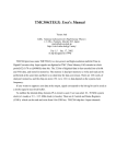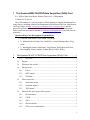
1
1 The Quarknet/WALTA/CROP Data Acquisition (DAQ) Card R. J. Wilkes, Hans-Gerd Berns, Richard Gran, Univ. of Washington Version: 2b, 23-Nov-03 Note: This manual is a work in progress, which attempts to compile information from many sources, including technical documentation by Hans Berns, Rik Gran, Sten Hansen, and Terry Kiper (see http://www.phys.washington.edu/~walta/qnet_daq/ ) and the practical experience of many other beta testers. It is “perpetually under construction”. Please send corrections and comments to [email protected] if you find errors or omissions. Quarknet DAQ Card Development Team members: 1 • Fermilab: Sten Hansen, Tom Jordan, Terry Kiper • U. Nebraska/Lincoln: Dan Claes, Jared Kite, Victoria Mariupolskaya, Greg Snow • U. Washington/Seattle: Hans Berns, Toby Burnett, Paul Edmon, Rik Gran, Ben Laughlin, Jeremy Sandler, Graham Wheel, Jeffrey Wilkes The Quarknet/WALTA/CROP Data Acquisition (DAQ) Card .................. 1 1.1.1 Overview ................................................................................................. 3 1.2 Purpose ............................................................................................................ 3 1.3 What does the card do? ................................................................................... 3 1.4 What goes in? .................................................................................................. 4 1.4.1 Power....................................................................................................... 4 1.4.2 PMT signals............................................................................................. 4 1.4.3 GPS data.................................................................................................. 4 1.5 What comes out? ............................................................................................. 4 1.5.1 Serial data stream .................................................................................... 4 1.5.2 On-board display..................................................................................... 4 1.5.3 TRG output.............................................................................................. 4 1.6 What are the major parts of the system? ......................................................... 4 1.6.1 Discriminators ......................................................................................... 5 1.6.2 CPLD....................................................................................................... 5 1.6.3 TDCs ....................................................................................................... 5 1.6.4 Microcontroller........................................................................................ 5 1.6.5 GPS receiver and interface...................................................................... 5 1 Quarknet/WALTA/CROP DAQ Card (11/23/2003) 1.6.6 2 3 Functionality................................................................................................................ 6 2.1 Threshold detection ......................................................................................... 6 2.2 Coincidence logic............................................................................................ 6 2.3 Rate counters ................................................................................................... 7 2.4 GPS data.......................................................................................................... 7 2.4.1 GPS startup.............................................................................................. 7 2.4.2 The 1PPS signal ...................................................................................... 7 2.4.3 How to calculate the event time .............................................................. 8 Output Data ............................................................................................................... 10 3.1 4 Auxiliary sensors..................................................................................... 6 Output format ................................................................................................ 10 Using the card............................................................................................................ 11 4.1 Basic coincidence counting........................................................................... 11 4.2 GPS observations .......................................................................................... 12 4.3 Measuring singles and coincidence rates ...................................................... 12 5 Figures....................................................................................................................... 14 6 Appendices ................................................................................................................ 19 6.1 Appendix A: Details of time and coincidence data-handling ....................... 19 6.2 Appendix B: Brief history of card development ........................................... 29 6.3 Appendix C: Acronym and Jargon Dictionary.............................................. 30 2 Quarknet/WALTA/CROP DAQ Card (11/23/2003) 1.1.1 Overview Development of the QuarkNet DAQ card was a collaborative effort involving Fermilab, U. Nebraska/Lincoln and U. of Washington/Seattle. See Appendix B for a brief summary of the project history. 1.2 Purpose The Quarknet/WALTA/CROP Data Acquisition card (“DAQ card” for short) takes signals from photomultiplier tubes (PMTs) and provides the kind of signal processing and logic that is basic to most nuclear and particle physics experiments. Signals from up to 4 PMTs can be analyzed. The board produces a record of output data whenever the PMT signals meet a pre-defined trigger criterion (for example, when 2 or more PMTs have signals above some predetermined threshold voltage, within a certain time window). The output data record, which can be sent via a standard RS-232 serial interface to any PC, contains information about the PMT signals, including how many channels had abovethreshold signals, their relative arrival times (precise to 0.75 nanoseconds), and the starting and stopping times for each detected pulse. In addition, an external GPS receiver module provides the absolute UTC time of each trigger, accurate to about 50 nanoseconds. This allows counter arrays using separate DAQ cards, for example different schools in a wide-area array, or two sets of counters at the same site, to correlate their timing data. Commands can be sent to the board to allow users to define trigger criteria, select various options, and retrieve additional data, such as counting rates, auxiliary GPS data, and environmental sensor data, in addition to trigger and PMT pulse information. 1.3 What does the card do? First, the DAQ card replaces the functions of the NIM electronics used initially in CROP and WALTA. It effectively provides discriminators and trigger logic for 4 channels of PMTs. The board includes 5 built-in scalers, allowing simultaneous counts of singles on each channel, plus triggers at whatever logic level the user specifies (2- to 4fold majority logic). These counters can be zeroed and then read out upon command. The DAQ card provides other functions not supplied by our NIM electronics. There is a simple, standard RS-232 interface which should work on any PC (Windows, Linux or Mac). The data stream consists of simple ASCII text lines which should be readable by any terminal-emulator program. In addition, a GPS clock provides accurate event time data synchronized to Universal Time (UTC), so widely-separated sites can compare data. In data-stream mode, the DAQ card outputs a series of text lines reporting event data: trigger time in UTC, with 24nsresolution, and absolute accuracy about 100 ns; leading and trailing edge times for each pulse recorded within the coincidence time window with 0.75nsprecision; and data from the GPS and internal clocks. Additional commands to the board allow temperature and barometric pressure sensors to be read, or download GPS housekeeping data, such as the number of satellites visible. 3 Quarknet/WALTA/CROP DAQ Card (11/23/2003) 1.4 What goes in? 1.4.1 Power The board requires a stable +5 VDC power supply, with 800 mA or greater capacity. A modular 110VAC to 5V/2.4A modular switching power supply, of the type used for many small electronic devices, is supplied with the board. Replacements are readily available at Radio Shack or similar stores. NOTE: it is important to distinguish these DAQ power supply modules from the 12V units used for the WALTA HV supply boxes, which are very similar in appearance! Connection of a 12V supply to your DAQ card will probably fry it… 1.4.2 PMT signals BNC coax connectors accept cables from the individual counters. Note that the channels are numbered 1, 2, 3, and 4 on the board, but we will refer to them as channels 0, 1, 2, and 3. This numbering scheme (starting from 0 instead of 1) is consistent with engineering and computer programming practice – get used to it! 1.4.3 GPS data The external GPS module is connected through a special cable, which has a seemingly-standard D connector (serial port connector) on the far end. This connector mates with the commercial GPS module’s serial connector. However, the special cable’s D connector actually contains a tiny circuit board with components needed to ensure good performance over 100 foot or longer cables. The GPS clock will not work if the special cable is not used. 1.5 What comes out? 1.5.1 Serial data stream The DAQ board connects to your PC’s serial port with a standard serial cable. If your PC does not have a standard RS-232 serial port, you can use a USB-to-serial converter, available commercially. 1.5.2 On-board display The board has a 4-digit numerical display which advances when counting, just to amuse your students. By default, it counts coincidence events since the last reset. 1.5.3 TRG output There is an extra port, which puts out a NIM standard logic pulse whenever a trigger occurs. This can be used to trigger other equipment if desired; at present it is not used in CROP or WALTA. 1.6 What are the major parts of the system? Fig. 1a shows a functional block diagram of the DAQ card, and Fig. 1b shows how the counters and other components should be connected to set up a counter system. Fig. 2a shows a photo identifying the main components. 4 Quarknet/WALTA/CROP DAQ Card (11/23/2003) 1.6.1 Discriminators PMT signals are first pre-amplified by a factor determined by a set of changeable resistors (amplification factor x10 is used for Quarknet, x2 by CROP, x1 by WALTA). Then discriminators are implemented, using voltage comparator chips, with the reference voltage adjustable via screwdriver-adjustable trimpots. Threshold levels can be set from 0 to -750 mV by adjusting each pot while monitoring voltage at a nearby test point. Remember that the voltage comparators look at the amplifier output, so raw PMT signal levels are multiplied by any amplification factor present. For example, if you used a -30 mV threshold with NIM discriminators and have x2 amplification, your threshold level on the DAQ card should be set to -60 mV. To avoid damage to the trimpots, use only the special sleeved screwdrivers supplied. 1.6.2 CPLD Trigger logic is implemented using a CPLD (Complex Programmable Logic Device) chip. Software revisions for this chip must be prepared using special software, but can be then downloaded via the serial port, allowing us to distribute updates that alter the fast logic if necessary. Any trigger logic level from singles to 4-fold can be set by commands to the card. Majority logic is used: any combination of 3 active channels causes a trigger at the 3-fold level, for example. 1.6.3 TDCs Discriminator output pulses are fed into TDCs (Time-to-Digital Converters) which are used to measure the arrival time of leading and trailing edges of pulses. They keep track of their state (high or low) at 0.75nstime intervals. If the trigger criterion is satisfied, the TDC data are latched and read out, giving leading and trailing edge times for each channel relative to the trigger time in units of 0.75 ns. This allows us to calculate PMT pulse widths (Time Over Threshold, or TOT, see Fig. 3) as a crude estimate of pulse area. Note: “TDC” is a generic term in particle physics technology. The specific chips used on the board were named TMCs (“Time Measurement Chips”) by their designers, and you may see this designation in some documentation. 1.6.4 Microcontroller The microcontroller chip (MCU – it is really just a special-purpose CPU) provides the onboard ‘slow’ logic (with time scale microseconds, not nanoseconds), which interfaces the board to the user via a terminal window or equivalent on your PC. At present, the MCU can be reprogrammed to redefine functionality only by using special software and burn-in hardware – not a do-it-yourself project, but at least the logic can be changed and updated if necessary. 1.6.5 GPS receiver and interface The external GPS module (Fig. 2b) is interfaced to the Quarknet DAQ board with a special cable, which can be over 100’ long if necessary. Although the GPS module’s RS5 Quarknet/WALTA/CROP DAQ Card (11/23/2003) 232 D plug appears conventional, it has been modified with a special connector, which contains the circuitry required to deliver DC power to the module and interface the 1PPS signal to the board. This connector should not be inserted directly into your PC’s serial port. You may wish to use the GPS module alone, for example to observe satellite data without operating the DAQ card. For standalone operation of the GPS module, you will need to construct a special adapter to allow connection of a +5VDC power supply directly to the module; you can use the same power supply used for the DAQ card. The wiring diagram for the adapter is shown in Fig. 2c. Parts shown in the wiring diagram can be obtained at any electronics supply store. The LED is optional and just blinks to display the 1PPS signal, indicating valid data. The GPS module itself is weatherproof, but the connectors should be protected. Also, we find the screws on the cover of the GPS module tend to rust, so they should be covered with plastic paint or nail polish before deployment outdoors. 1.6.6 Auxiliary sensors There is a temperature sensor built into the microcontroller chip, so CPU temperature can be measured. This temperature and the supply voltage are reported whenever the board is started up. While the board components are rated for temperatures between –20C and +80C, the board temperature should not normally go above about 50C. A second temperature sensor is located on the booster board built into the GPS cable’s ‘far end’ DB9 connector, i.e. about 3 feet from the GPS module. This can be used to log outdoor temperature at the counter locations, for example. This sensor is read out with a special command, as described below. A barometric pressure sensor is built into the board. Details on its use will come later. 2 Functionality The way the DAQ card defines event triggers differs subtly from the way the NIM coincidence units work. Please read the following carefully! 2.1 Threshold detection As mentioned, the PMT signals are fed first to amplifiers, then to voltage comparators. The comparators set a HIGH logic level whenever the amplified PMT signal exceeds their reference voltage setting. This logic level has 0.75nsresolution. This means we can actually measure the time difference between pulses on different channels at the same site down to less than a nanosecond! Of course, we depend upon the GPS clocks, with 24nsresolution, for timing between school sites. 2.2 Coincidence logic In the NIM coincidence modules, the majority trigger logic is easy to understand. For example, if we select 2-fold coincidence, whenever any 2 inputs (which are discriminator output logic signals) go HIGH within a fixed time interval (100 ns, typically), the logic unit outputs a pulse of fixed width (typically also 100 ns). 6 Quarknet/WALTA/CROP DAQ Card (11/23/2003) The DAQ card works in a slightly more complicated way. This compromise was necessary to implement the performance we need on a low-cost board. For example, if the trigger criterion is set to 2-fold, then as soon as any channel goes above threshold, a 240-nanosecond wide time window is opened (window width is adjustable). If any other channel goes above threshold during this time window, all event data are latched and output for the overlap time interval when both are active. Notice that pulse data are reported for a time interval that is not of fixed length, but just covers the overlap period when 2 or more channels are active. Leading and trailing edge times are reported for any active channels (not just for the 2 channels that launched the trigger), with empty data entries for channels that remained inactive during the trigger window. For a single event trigger, the DAQ card may need to output several lines of data, depending on how many pulses are present in the event. The first line has an “event flag” for identification. Any following lines without this flag are simply additional data for the same event. 2.3 Rate counters The card has 5 built-in counters, numbered 0 through 4, which work just like NIM scalers. Counters 0 through 3 record the singles count for each channel, and counter 4 records the trigger count for whatever coincidence level you have set. By zeroing these counters with a software command, then running the card for a fixed length of time and reading out the counters at the end, you can obtain singles rates for each channel and the rate of coincidence events. 2.4 GPS data 2.4.1 GPS startup Once powered up, the GPS module should quickly “find itself” if it is in a location with a clear view of about half the sky or more. Usually it does not work well through windows and should be physically outdoors, but in some buildings it can be left on a windowsill. The receiver will lock onto 4 or more satellites, download the data needed to operate accurately, and start averaging its position and clock settings at one-second intervals. Within a few minutes after startup, you should have accurate GPS data. The unit’s LED display blinks red when first powered-up and searching, and changes to steady green when it has acquired enough satellite data to locate itself accurately. Time data are not accurate until then. The GPS module provides several kinds of data. The commercial GPS module directly supplies the date and “coarse” time (in UTC, not local time) down to milliseconds, or three decimal places after seconds, and reports its geographic location in latitude and longitude down to the equivalent of a few 10s of meters. 2.4.2 The 1PPS signal The stock LeadTek GPS module was modified slightly for our application, to allow the more precise timing we need, down to 10s of nanoseconds (8 decimal places following integer seconds). The GPS receiver outputs a logic pulse at the beginning of each UTC second, called the 1PPS (1 Pulse Per Second) signal. In principle, the leading 7 Quarknet/WALTA/CROP DAQ Card (11/23/2003) edges of 1PPS signals from GPS receivers anywhere in the world are all in synch, to within the accuracy of the non-military GPS system, about 100 ns. This feature allows us to do accurate time synchronization between school sites. The special connector and cable we attach to the commercial GPS module allows us to transmit the 1 PPS signal about 100 feet or more without excessive timing degradation. 2.4.3 How to calculate the event time The way we get nanosecond accuracy is simple. The DAQ card has onboard a simple, cheap 41.667 MHz oscillator, which thus “ticks” every 24 nanoseconds (1/41.667x106 sec). Of course, such a device does not maintain its frequency very accurately, and our oscillator’s frequency may drift by 10 to 100 Hz from its nominal value – or more, under extreme temperature changes. We simply keep a counter (scaler) counting the clock ticks. (Whenever this 32-bit counter reaches its maximum capacity of 4.3 billion, approximately every 100 seconds, it just “rolls over” back to zero, like an old car’s odometer, and continues counting). All we need to do is log the reading of the internal clock counter every time a 1PPS signal arrives. Then we know how many oscillator cycles actually occurred during the past second, and can calibrate our clock using the GPS system. In this way we can take advantage of the US government’s multimillion-dollar array of atomic clocks that calibrate the GPS system continuously! So if we log the counter reading every 1PPS, and also whenever a trigger occurs, we can find the precise event time as follows: get the date and time down to the nearest second from the GPS module’s coarse time (with one correction, described below); find the number of clock ticks between the last 1PPS and the event trigger, and divide by the number of clock ticks between the last two 1PPS pulses, to get the fraction of a second down to 24nsprecision. Of course, if the counter rolled over during the last second we have to take that into account when doing the arithmetic. There is a caveat to the previous paragraph: if the data rate is very slow – less than about one event per 100 sec – the internal counter may roll over more than once between readings. In this case, all bets are off, and the seconds cannot be reliably calculated. In the next firmware update, we will implement commands to produce an output line at each 1PPS, and/or automatic DG commands at regular intervals, ensuring that the necessary information is logged between counter rollovers. One minor correction is also needed: the GPS module reports the time in down to milliseconds, but there is a delay of a fraction of a second relative to the 1PPS edge. For example, when the 1PPS signal tells us it is exactly 12:01:25.000000000, the GPS time field in the data record may say it is 12:01:24.850. This delay (reported as +0.150 sec in this example) will cause us to associate the wrong integer second with the event time if we are not careful. (The GPS time delay may be negative, i.e. a forward shift, with the ASCII time data ahead of the 1PPS signal.) The DAQ card is programmed to list the delay in milliseconds for each data record, so the reported time in seconds can be corrected to match the 1PPS data. The algorithm described below implements these calculations. 8 Quarknet/WALTA/CROP DAQ Card (11/23/2003) Note for people who like really deep-down details: the delay mentioned above, which we can determine and correct, is not the whole story. There is an additional delay of 150250 millisec, which is unresolvable, since it is buried in the manufacturer’s firmware. Luckily, it is too small to cause the rounding procedure described above to go wrong. Remember, all this is just about determining the integer seconds part of the time. Nanosecond-level timing is not affected. Also, we have not discussed corrections for the antenna cable delay: the event time calculated is when coincidence occurs at the DAQ board, not at the counters. This is of no consequence as long as all school sites in an array use approximately the same cable lengths, within a few 10s of meters. Here is an algorithm showing how to get the precise event time: tCOARSE = hh : mm : ss.sss, mm : dd : yy from data record delay = ± 0.ddd integer seconds : ss = round (ss.sss + 0.ddd) to nearest second N X = clock count at time X : Clock rate R1 = (N LATEST_1PPS - N PREVIOUS_1PPS ) ticks/sec ( N TRIGGER − N LATEST _1PPS ) t NANOSEC = R1 tEVENT = ss + t NANOSEC Alternatively, use a K - second running average for the clock rate : ( N LATEST _1PPS − N Kth _ PREVIOUS _1PPS ) RK = K The following example illustrates this calculation: EXAMPLE : 7EEED53B A3 36 30 3F 00 01 00 01 7EE62DDD 175402.082 080803 V 00 0 +0887 hh : mm : ss.sss = 17 : 54 : 02.082 ss.sss = 02.082 ddd = +887 → 0.ddd = 0.887 ss = (2.082 + 0.887) = 2.969 : round → ss = 03 trigger : 7EEED53B HEX = 212958137110 last 1PPS : 7EE62DDD HEX = 212901423710 ( previous 1PPS ) : 7C6A6587 HEX = 208734759110 ( must look back in datafile for previous ) R1 = ( 2129014237 - 2087347591 ) = 41, 666, 646 ticks/sec (2129581371 − 2129014237) 567,134 = = 0.013611222 t NANOSEC = 41, 666, 646 41, 666, 646 tEVENT = ss + t NANOSEC = 3.013611222 so this event occurred at 17 : 54 : 03.013611222 on 8/8/03 9 Quarknet/WALTA/CROP DAQ Card (11/23/2003) 3 Output Data Fig. 4 shows the command summary obtained when you send the command help. Several of the commands will only be needed by experts. Here, we will focus on the commands highlighted in Fig. 4, and their response formats. 3.1 Output format Fig. 5 shows screen shots with typical data displays, as viewed in a terminal connected to the card. Scaler data: The command CD disables counters, CE enables (starts) the counters, and DS displays the counter contents in hexadecimal, followed by a continuous record of event data as described below. Scalers 0-3 store the singles rates for channels 0-3, and counter 4 records the number of n-fold coincidences, where n is whatever level you set. These counts are running totals since the last time the counters were zeroed. The reset commands RB (reset counters and TMC only) or RE (reset everything, including card setup parameters you may have changed) will zero all counters. Individual channel pulse data: The command sequence CE, DS will cause event records to be written as coincidences are found, after first giving scaler contents. Each event record may contain several lines of data. Appendix A gives a detailed description of the data format and its interpretation. Housekeeping and auxiliary sensor data: The command TH reports the reading of the temperature sensor on the GPS module connector, about 3 feet from the GPS module itseslf. The miniature circuit board inside the connector does not generate significant heat, so the sensor’s reading will provide an accurate measurement of the temperature at the sensor’s location (e.g., outdoor air temperature, or temperature inside a counter housing). The GPS module may be damaged if its temperature goes below –40C or above +85C. This temperature is also reported at power-up or reset. The command BA reports the pressure sensor reading; this function has not been fully implemented yet (as of 9/03). At DAQ card power-up or reset, the temperature on the DAQ card (actually, inside the MCU chip) is reported. Note that this is not a good indicator of air temperature at the card site, even if the card is located outdoors, since the chip generates considerable heat while operating. It is a useful way to make sure the card is healthy, however! Temperatures over +40C may be dangerous to the card’s chips. At power-up, housekeeping data like the MCU voltage (which should be 3.3V), and the card’s unique serial number (which may be needed for upgrades) are reported. 10 Quarknet/WALTA/CROP DAQ Card (11/23/2003) 4 Using the card Fig. 1b shows how to hook up the components of your detector system. Here we give simple command sequence recipes for common experiments: 4.1 Basic coincidence counting We want to set up the card by disabling and zeroing the onboard counters, and setting our desired values for the parameters d and w (see Appendix A for details). Note that d and w are in units of 24 ns. The startup defaults are d=6 and w=10, which are good for muon telescopes. For air shower detectors, set d=50 and w=100. Reset the card, to zero counters and set everything to defaults (unless the card was just turned on): RE Disable the counters and TMC CD Set the value of d (TMC delay): Set the time registers, with read pointer (register 01) = 00, and the write pointer (register 02) to d, in hexadecimal. The TMC delay d will be the difference of these values (so in fact you could set 01 to some value nn, and 02 to nn+d). For example, if we want d=6, WT 01 00 WT 02 06 To get d = 50 ticks, we would set register 02 to 32H = 5010. The maximum is 7FH = 12710. Set the coincidence level, and enable desired channels Set control registers with the WC (Write Control register) command. Register 0 sets the coincidence level, using its first (left) hex character. Here, 0 means singles, 1 means 2fold, and n-1 means n-fold coincidence level is to be required. The second (right) hex character represents the desired pattern of enabled/disabled channels in its bits, with 0s for disabled channels and 1s for enabled channels. Thus, for example, WC 00 1F means set 2-fold coincidences with all 4 channels enabled: FH = 1111. If you wanted to disable channel 2 you would use 1101 = DH. So, to enable 3-fold coincidences with channel 2 turned off, you would use WC 00 2D. Set the value of w (gate width): Registers 2 and 3 hold the gate width setting, in integer clock ticks (units of 24 ns). Just to confuse you, the lower 8 bits of the binary number representing w go in register 2, and the higher 8 bits in 3. So if abcd is the desired gate width w in hexadecimal, we would use WC 02 cd 11 Quarknet/WALTA/CROP DAQ Card (11/23/2003) WC 03 ab For example, to get w= 100 clock ticks (10010 = 0064H = 0000 0000 0110 01002; notice how handy hex is for representing binary numbers compactly?) WC 02 64 WC 03 00 Re-enable the onboard counters (counting will begin immediately): CE When done counting, to read out the counts, first stop the counters: CD Then read and display their contents: DS 4.2 GPS observations To read out the current GPS time, latitude, longitude, altitude and number of satellites in view, GP Note: You can directly monitor the GPS module’s serial data stream by sending the command NM 1 This command will pass all data from the GPS module directly to your PC. Normally, the board’s MCU reads, interprets and distills the raw GPS information to produce the DG command output; this will continue to be true even after you send the ‘NM 1’ command, but you will get many more lines of detailed data, in the GPS industry’s standard NMEA format (see for example http://www.phys.washington.edu/~berns/archive/Leadtek/GPS_Protocol_ReferenceManual.pdf), To disable NMEA data-forwarding and return to normal operation, send the command NM (i.e., no ‘1’) Note: If you connect the GPS module directly to your PC’s serial port, via the adapter shown in Fig. 2c, you can also use a software package provided by LeadTek (see http://www.phys.washington.edu/~berns/archive/Leadtek/GMonitor.exe) to display sky maps of satellites and other interesting data. 4.3 Measuring singles and coincidence rates The previous section described how to get total counts of coincidences. Of course you could start, stop and read the counters using a stopwatch, as when using NIM scalers, but the GPS clock is a better stopwatch. To get rates, do the following: Do the setup procedures described above, up to the CE command. 12 Quarknet/WALTA/CROP DAQ Card (11/23/2003) Get the GPS time and immediately start counting: DG CE After an appropriate length of time, stop and immediately get the GPS time: CD DG Read out the total counts: DS Then divide counts by elapsed time (difference between times reported in the before and after GPS readings) to get rates. Of course, the elapsed time is long by a fraction of a second, depending on how quickly you can enter the pairs of commands needed to start and stop. 13 Quarknet/WALTA/CROP DAQ Card (11/23/2003) 5 Figures Figure 1: a) Block diagram of DAQ card; b) System hookup diagram 14 Quarknet/WALTA/CROP DAQ Card (11/23/2003) Fig. 2: a) Photo of card with components identified b) LeadTek GPS module (with custom connector): 15 Quarknet/WALTA/CROP DAQ Card (11/23/2003) c) Standalone adapter wiring diagram. Construct this adapter to allow direct operation of the GPS module via a PC serial port, without a DAQ card. The LED is optional and simply blinks to display the 1PPS signal, to indicate when the GPS module has locked onto a position and time fix. 5VDC power can come from a 110VAC adapter or a PC mouse jack. Shown: Power is taken from your PC or laptop’s PS/2 mouse jack. Power drawn is equivalent to what a mouse would consume, and will not affect your computer. You can substitute a connector to mate with a standard 5VDC power adapter, available from any electronics store. 16 Quarknet/WALTA/CROP DAQ Card (11/23/2003) Figure 3: Time Over Threshold (TOT) thresh T Figure 4: Command list (help screen): Scintillator Card, QNET2 Firmware Ver2.3, 09/09/03 HE=Help Serial#=1002 uC_Volts=3.3 uC_TempC=26.6 GPS_TempC=235.0 Barometer Counter DC DF DG DS DT Flash GP Help NA n NM n Reset SA n SB n SN nnnn ST n TH WC mm nn WT mm nn - kPa=0 BA=Display, BA bb.b gg.g calibrates kPa Baseline, Gain (See HB). CE=Enable, CD=Disable, Controls TMC Running bit @ CPLD CCR1. Display Counters and Control Registers of CPLD, address 0-4. Display Scalar Fifo Data (first 12 Bytes as three 32bit numbers). Display GPS Date, Time, Position and Status. Display Scalar Fifo, Counters 0-3, Triggers, and 1_PPS Time. Display Time Control Registers of TMC, address 0-3. FL=Load Binary File, FR=Read SumCheck, FC=Copy_to_CPLD. Init Link with GPS unit (GGA=1/sec, RMC=1/sec, disable others). HF=Trigger format, HS=Status format, HB=Barometer format. NMEA GPS Data Append (n==1 On),(n!=1 Off), add GPS to output. NMEA GPS Data Echo (n==1 On),(n!=1 Off), (GPS_Baud=9600). RB=TMC+CPLD, RE=MSP430+TMC+CPLD. SA=Save TMC+CPLD Registers to Flash, (SA 1=Restore Defaults). Set Baud Rate (PC Link), 1=19200, 2=38400, 3=57600, 4=115200. Serial Number(BCD), SN=Display Number, SN nnnn=Store Serial Number. Send Status Data (n==1 On),(n!=1 Off), (See HF). Thermometer Data Display, -40 to 99 degrees C. Write Counter Control Registers CPLD address mm with data nn. Write Time Control Registers TMC address mm with data nn. 17 Quarknet/WALTA/CROP DAQ Card (11/23/2003) Figure 5: Screen shots showing results from common commands: 18 Quarknet/WALTA/CROP DAQ Card (11/23/2003) 6 Appendices 6.1 Appendix A: Details of time and coincidence data-handling This appendix is for users who want to understand the operation of the card in more detail. Warning: it gets technical fast. To keep the cost low, our great engineers created a very clever scheme for handling the tasks we need with minimal resources. Of course, “clever” also means “not simple”. For this reason, the way in which triggering is handled differs in some details from what one would expect from simple modular fast electronics like NIM coincidence units. The card handles coincidences as described below. We define define two parameters, which the user can set: 1) w = Gate Window – just like the “width” setting in a NIM module, it determines how close together pulses must be to cause the card to trigger. Note: in digital electronics, the term “gate” means a signal used to enable (“open the gate for”) passage of other signals or data. 2) d = TMC delay – complicated to define precisely, but it determines which pulse edges get read out into the data stream when a trigger occurs, by delaying this information until the trigger actually happens. Both w and d are measured in units of 24 nanoseconds, the internal clock tick interval. The meaning of w is familiar if you have used NIM coincidence modules before, but both w and d will be explained below. First we consider the actual physical quantities that interest us, and then relate them to these two parameters. o TTRG = maximum time window during which real physics processes we want to study might cause a trigger. In other words, if we set the card for 2-fold coincidences and one channel gets a signal at t=0, at least one other channel must show a signal before t= TTRG or we will lose detailed information about that pair of pulses. See examples below. o TWIDTH = the duration after the first pulse in a trigger, during which we want to record all rising and falling edge times. The channel in which these extra pulses occur does not matter, all of them will be saved. Then we should set the values of w and d as follows: o Set d > TTRG, but no smaller than two clock ticks. o Set w > TWIDTH + d – 1. For example, if we want to build a muon telescope with counters less than a meter apart, TTRG is the time it takes a muon to go from the top counter to the bottom counter, traveling at the speed of light (about a foot per nanosecond). Thus TTRG is only a few ns, so we should set d to the minimum value of 2 clock ticks, or 48 ns. Similarly, to simply count muons, we are only interested in a short time window for edges, so we could take TWIDTH = 48 ns also. Then we should set d = 2, and w = 3. 19 Quarknet/WALTA/CROP DAQ Card (11/23/2003) However, if we want to look for muons that stop and decay (2.2 microseconds mean lifetime) in a third counter, we need to look for the decay electron pulses several microseconds after the trigger, so we should have TWIDTH = 400 (9600 ns, or about 10 microseconds). Thus we would set d = 2, and w = 401. As another example, in extensive air showers we expect the main “pancake” of arriving particles to be between 10 m and 200 m thick, so the earliest and latest particles might arrive at our counters about 0.6 microseconds apart, for a vertical shower. Thus we want to have TTRG be about 1 microsecond. TWIDTH can be about the same. So we might want to set d = 50 (= 1.2 microseconds) and w = 100. However, we should not set huge time windows “just to be safe”, or the card will be busy all the time, and its effective dead time will become a serious problem. The values of d and w should be kept as small as possible consistent with the given physics goals. Default values, effective when the card is powered up, are d = 6 (i.e., 144 ns) and w = 10 (240 ns). These values are optimal when the card is used for a muon telescope experiment, but for air shower detectors larger values are preferable, and must be set by the user. We suggest using values of d = 50 and w = 100 for air shower detectors, as in the example above. Now back to the details that go into the formula for d and w. Whenever an above-threshold voltage is detected on any channel, that channel turns on an internal trigger bit for w clock ticks (w x 24 ns). At the end of that time the internal trigger bit is reset to zero. The card’s startup default setting is for “1-fold” coincidence, which means it will trigger on singles: any above-threshold signal on any channel produces output data. Unless your PMTs are extremely quiet, actually triggering on singles will quickly overwhelm the card - with the serial port set at 38 kbd, trigger rates over 30 Hz cannot be handled. When the card is set for two-fold coincidences, a trigger is declared any time that two or more channels' trigger bits are 1 simultaneously. If you set the card for three-fold coincidence, then it requires three channels with their bits set simultaneously, and similarly for four-fold. However, the trigger bits must overlap by at least one 24 ns clock tick to activate a trigger. If one channel's bit drops and another rises, no trigger will occur. Also, the trigger is active for exactly the overlap period. The card has a TRG output that will go high when a trigger occurs - you can watch this on the oscilloscope, and see its duration change as the signals are closer or further apart. The TMC Delay d is very different than the almost-just-like-NIM coincidence described above. The technical issue is this: we don't just want to count triggers, we also want to record all the edges that contributed to a given trigger. It is hard to program the circuits inside the board to look back in time to the first pulse that contributed to the trigger when the second pulse might have arrived a significant amount of time later. (It was also hard to make the old NIM modules do this.) Instead, we separate the thing that generates the trigger from the part that reads out the timing information and then we 20 Quarknet/WALTA/CROP DAQ Card (11/23/2003) delay this detailed timing information so that it is read out after the trigger is generated. Then the card only needs to save information that happens when the gates overlap. In the old days, when NIM modules were state-of-the-art, this could not be done just by programming a chip. It had to be done by splitting the signal, using part of it for the trigger, and sending the other part through long cables so that it arrived late, after the trigger logic was firmly set in motion. Consider the card’s startup default settings, d = 6 and w = 10. Imagine a physics event where one pulse arrives three clock ticks after another. The trigger will occur when the second pulse arrives, so three clock ticks after the first, the card detects trigger bit overlap, and the TRG output goes high. But internally, pulse edge time information is delayed six clock ticks (d = 6) , so the information about that first pulse is now available after just three more clock ticks (the trigger is still on). The information about the second pulse arrives after another three ticks (again, the trigger is still on). Because both edges appear when the trigger is on, they will appear in the data stream sent to the computer. As an exercise for the reader: using these default values and remembering that the width of the trigger varies depending on whether the pulses are close together or far apart, what would cause a pulse edge to not appear in the data stream, even though the card actually triggered? The conclusion of this problem is that there might be information in the data stream that does not correspond to the physics processes we want to study. On to some concrete examples: 21 Quarknet/WALTA/CROP DAQ Card (11/23/2003) Here are three examples of event timing diagrams showing 2-fold coincidences, with d=6, w=10. In each case, pulses of width 2 clock ticks (48 ns) arrive at inputs 0 and 1, but with different time separations in each example. The timing diagrams show the discriminator output, the channel trigger gate, and the TMC output after delay d, for each channel, plus the coincidence trigger gate, and the edge time information obtained from the TMC upon readout. Example A: Signal in channel 1 arrives 2 clock ticks (48 ns) after signal in channel 0. Notice that the trigger gate is 8 ticks long (overlap time of the two 10-tick channel gates). All edges get reported. Fig. A1: pulse timing diagram of example A. 22 Quarknet/WALTA/CROP DAQ Card (11/23/2003) Example B: Signal in channel 1 arrives 3 clock ticks (72 ns) after signal in channel 0. In this case, the trailing edge of the delayed TMC signal for channel 1 lies outside the card trigger gate (overlap time of the individual channel gates), so only its leading edge is reported. Fig. A2: pulse timing diagram of example B. 23 Quarknet/WALTA/CROP DAQ Card (11/23/2003) Example C: Signal in channel 1 arrives 5 clock ticks (120 ns) after signal in channel 0. Note that the delay value is 6 clock ticks (144 ns). So in this case, both edges of the signal on channel 1 lie outside the trigger (overlap) window and are not reported. If your physics application involves simply counting triggers (as in a muon telescope), no problem. But if you are analyzing edge time data, as in a muon decay or air shower experiment, this would appear to be a 1-fold event! If this situation represented a real physics process you wanted to study, you would need to lengthen the values of d and w to accept all the edges in this event. Otherwise, it will look like a random background event that you have to eliminate or ignore when you analyze the data. Homework problem: what would happen if we had set w=2d+1=13, instead of 10? Fig. A3: pulse timing diagram of example C. 24 Quarknet/WALTA/CROP DAQ Card (11/23/2003) The next example is an actual event recorded by the DAQ card, on Aug. 8, 2003, when we had a mini-array of 4 counters set up. In this example, the card was set with d=6, w=10 (the default startup values), and for 2-fold or greater coincidence level. Notice the data stream had 5 lines of data for this single event. Example D: 80EE0049 80EE004A 80EE004B 80EE004C 80EE004D 80 24 21 01 00 01 3D 01 2A 01 00 25 00 00 00 01 01 23 01 01 38 00 00 00 00 01 01 01 01 39 3C 00 00 00 32 01 01 01 01 2F 7EB7491F 7EB7491F 7EB7491F 7EB7491F 81331170 202133.242 202133.242 202133.242 202133.242 202133.242 080803 080803 080803 080803 080803 A A A A A 04 04 04 04 04 2 2 2 2 2 -0389 -0389 -0389 -0389 +0610 The pulse timing diagram (Fig. A4) below shows the four PMT channels’ trigger bits vs time in nanoseconds. (Remember, channels are numbered 0 through 3). Pulse edge times are recorded with 0.75 ns precision. Recall, however, that the trigger logic works in time bins of 24 ns. Fig A5 shows the channel trigger bits vs time, in units of 24 ns. The following sequence of events occurs: 1. The first pulse arrives on channel 2 at t=1 (in units of 24 ns). Trigger gate 2 is set for 10 ticks. The TMC records the pulse’s leading edge at 18 ns relative to the last 24ns clock tick. 2. Three nanoseconds later, a pulse arrives on channel 3. Trigger gate 3 is set for 10 ticks. The TMC records this pulse’s leading edge at 21 ns. 3. Trigger gates 2 and 3 are set simultaneously, so a trigger gate (TRG) is asserted. If no further signals arrived, the trigger would stay on for ten 24ns time bins (240 ns) since the signals on channels 2 and 3 arrived inside the same clock tick. 4. In 24ns time bin #2, pulses arrive in channels 0 and 1, setting their trigger gates for 10 ticks. Thus the 2-fold coincidence requirement is met continuously from time bin 1 until time bin 11, a total of 11 clock ticks or 264 ns (shaded area in Fig. A5). 5. At the end of this interval the trigger gates for all channels are down, so the TRG gate is dropped. The pulse edge times stored during the time the trigger was on are read out of the TMC chip and reported. 6. Only edges that are within the trigger interval after they have been delayed by 6 ticks are put into the data stream. Thus, all the pulses in Figure A4 are recorded, but the second falling edge of channel three (which is off the figure to the right) will fall outside the shaded area in Figure A5 and will not be recorded. Note: The actual values encoded in the data stream represent the delayed times. If it is vital to get the actual time for each edge, then each of them actually arrived d x 24 ns earlier than the time given in the data record. Usually only relative timing matters, and this kind of accuracy is not necessary. The interpretation of the edge time data is explained in Fig. A6. 25 Quarknet/WALTA/CROP DAQ Card (11/23/2003) Fig. A4: Discriminator output timing diagram of example D. Fig. A5: Channel gate timing diagram (card trigger interval is shaded). 26 Quarknet/WALTA/CROP DAQ Card (11/23/2003) Fig. A6: Interpretation of data records for example event. See also http://www.phys.washington.edu/~berns/WALTA/Qnet2/misc/DAQ_output_format.txt 80EE0049 80EE004A 80EE004B 80EE004C 80EE004D 80 24 21 01 00 01 3D 01 2A 01 00 25 00 00 00 01 01 23 01 01 38 00 00 00 00 01 01 01 01 39 3C 00 00 00 32 01 01 01 01 2F 7EB7491F 7EB7491F 7EB7491F 7EB7491F 81331170 202133.242 202133.242 202133.242 202133.242 202133.242 080803 080803 080803 080803 080803 A A A A A 04 04 04 04 04 2 2 2 2 2 -0389 -0389 -0389 -0389 +0610 - 5 data lines for this event: the first line has a trigger tag in the RE0 number (2nd field is > 80), followed by 4 lines without trigger tag (2nd field < 80). In all 5 lines: - GPS date is the same: 080803 = August 8, 2003; - GPS status: A = valid; - Number of GPS satellites tracked: 04 = 4 satellites. - DAQ status flag = "2" in all 5 lines: bit0=0: no 1PPS pulse pending bit1=1: trigger interrupt pending = data in TMC (not empty) (possible high rate if bit1 is not 0 at end of event) bit2=0: GPS data OK bit3=0: CPLD frequency OK - 1PPS count in lines 1-4 = 0x7EB7491F 1PPS count in line 5 = 0x81331170 => difference = 0x027BC851 => CPLD freqency currently = 41666641 Hz => 1 CPLD cycle = 1/41666641 sec = 24.000014784 ns - GPS time (down to integer second) of the 1PPS signal leading edge: Delay is -389 milliseconds for lines 1-4 (last field in the line) round(202133.242 - 0.389) = 20:21:33 UTC Delay is +610 milliseconds for line 5 GPS time of the 1PPS pules in line 5: round(202133.242 + 0.610) = 20:21:34 UTC - trigger count in line 1 = 0x80EE0049 => difference from 1PPS count: 0x80EE0049-0x7EB7491F hex = 37140266 decimal => time since last 1PPS pulse: 37140266 * 24ns = 0.891366384 seconds (assuming CPLD frequency is the nominal 41666667 Hz!) => absolute trigger time of this event = 8/8/2003 20:21:33.891366384 (*) computing the corrected absolute time by using the measured CPLD frequency of 41666641 Hz (from consecutive 1PPS counts, see above): => time since last 1PPS pulse: 37140266 / 41666641 = 0.891366933 seconds => absolute trigger time of this event = 8/8/2003 20:21:33.891366933 (So assuming the nominal frequency - exactly 24.00 ns CPLD ticks – would result in a 549 ns error in this example) Pulse edge data: - line 1: "80EE0049 80 01 00 01 38 01 3C 01": trigger count: 0x80EE0049 = 2163081289 (decimal) RE0: 80 => bit7=1: trigger flag for this event; bit5=0: input 0 has no rising edge. FE0: 01 => input 0 has no falling edge (bit5=0, so ignore bits0-4). RE1: 00 => input 1 has no rising edge. FE1: 01 => input 1 has no falling edge. RE2: 38 => bit5=1: input 2 rising edge (bits0-4)= 0x18 27 Quarknet/WALTA/CROP DAQ Card (11/23/2003) => 24/32 * 24ns = 18.0 ns. FE2: 01 => input 2 has no falling edge. RE3: 3C => bit5=1: input 3 rising edge = 0x1C => 18/32 * 24ns = 21.0 ns. FE4: 01 => input 3 has no falling edge. - line 2: "80EE004A 24 3D 25 01 00 01 00 01": trigger count: 0x80EE004A = 2163081290 (decimal) => +24nsfrom trigger count at event start (line 1). RE0: 24 => input 0 rising edge = 0x04 => 3.00 + 24 = 27.00 ns. FE0: 3D => input 0 falling edge = 0x1D => 21.75 + 24 = 45.75 ns. RE1: 25 => input 1 rising edge = 0x05 => 3.75 + 24 = 27.75 ns. FE1: 01 => input 1 has no falling edge. RE2: 00 => input 2 has no rising edge. FE2: 01 => input 2 has no falling edge. RE3: 00 => input 3 has no rising edge. FE3: 01 => input 3 has no falling edge. - line 3: "80EE004B 21 01 00 23 00 01 00 01": trigger count: 0x80EE004B = 2163081291 (decimal) => +48 ns from trigger count at event start (line 1). RE0: 21 => input 0 rising edge = 0x01 => 0.75 + 48 = 48.75 ns. FE0: 01 => input 0 has no falling edge. RE1: 00 => input 1 has no rising edge. FE1: 23 => input 1 falling edge = 0x03 => 2.25 + 48 = 50.25 ns. RE2: 00 => input 2 has no rising edge. FE2: 01 => input 2 has no falling edge. RE3: 00 => input 3 has no rising edge. FE3: 01 => input 3 has no falling edge. - line 4: "80EE004C 01 2A 00 01 00 01 00 01": trigger count: 0x80EE004C = 2163081292 (decimal) => +72 ns from trigger count at event start (line 1). RE0: 01 => input 0 has no rising edge. FE0: 2A => input 0 falling edge = 0x0A => 7.50 + 72 = 79.50 ns. RE1: 00 => input 1 has no rising edge. FE1: 01 => input 1 has no falling edge. RE2: 00 => input 2 has no rising edge. FE2: 01 => input 2 has no falling edge. RE3: 00 => input 3 has no rising edge. FE3: 01 => input 3 has no falling edge. - line 5: "80EE004D 00 01 00 01 00 39 32 2F": trigger count: 0x80EE004D = 2163081293 (decimal) => +96 ns from trigger count at event start (line 1). RE0: 00 => input 0 has no rising edge. FE0: 01 => input 0 has no falling edge. RE1: 00 => input 1 has no rising edge. FE1: 01 => input 1 has no falling edge. RE2: 00 => input 2 has no rising edge. FE2: 39 => input 2 falling edge = 0x19 => 18.75 + 96 = 114.75 ns. RE3: 32 => input 3 rising edge = 0x12 => 13.50 + 96 = 109.50 ns. FE3: 2F => input 3 falling edge = 0x0F => 11.25 + 96 = 107.25 ns. 28 Quarknet/WALTA/CROP DAQ Card (11/23/2003) 6.2 Appendix B: Brief history of card development Development of the DAQ card was driven by the need to provide a very low-cost set of front-end electronics to participants in school-network cosmic ray detector projects. Initially, projects like CROP and WALTA supplied schools with NIM crates and modules, on loan from Fermilab. The loaned equipment had a book value of about $10K per school, although in fact most of the modules were obsolete and no longer in demand for current experiments. However, off-the-shelf NIM modules to handle GPS timing data and interface to PCs in a simple way did not exist. Thus, while adequate for training and initial experiments by teachers and students, these wide-area network projects could not begin real data taking with the NIM hardware. Meanwhile, it was clear to engineers working in particle physics that, for experiments like these with very small numbers of channels, off-the-shelf fast electronics modules could be replaced with new programmable logic and time digitizer chips at very low cost. At the request of Tom Jordan of Quarknet, engineers Sten Hansen and Terry Kiper at Fermilab developed a prototype front-end card for a simple table-top cosmic ray demonstration detector. This ‘Version 1’ Quarknet card put together components that were cheap and reliable, but highly capable, integrating on a single small board the discriminator, logic and scaler functions of NIM modules for four PMT channels, with a simple, universal PC interface. However, only relatively coarse (~20 ns) pulse timing information could be provided. At the SALTA Workshop, held as part of the Snowmass-2001 meeting, the Quarknet team from Fermilab joined the WALTA and CROP teams to plan an improved Version 2 card. The goals were: nanosecond local timing, <100 nanosecond absolute timing, report all pulse edge times within a reasonable time window, up to 4-fold majority logic, total cost under US$500. Remarkably, these goals were quickly achieved! A team at KEK, the Japanese equivalent of Fermilab, had developed a time-to-digital module for the ATLAS particle physics experiment using a custom-made ASIC chip called TMC (Time Measurement Cell). Samples were available at Fermilab, and were used in the new board design to provide the detailed, precise timing data needed for air shower detectors. In addition, the TMC chips allowed us to perform TOT estimates for pulse area. UW engineer Hans Berns designed and implemented an on-board system to integrate data from a very low-cost (US$100) GPS receiver module, providing the final piece of missing functionality. The Fermilab team revised the board and its firmware to better encompass the needs of air shower experiments. Team members at Seattle and Lincoln worked on user-friendly LabView® interfaces for the cards, as well as black-box DAQ software for standard tasks. After CROP and WALTA lab-tested prototypes, production specimens of Version 2 cards were distributed in summer, 2003. 29 Quarknet/WALTA/CROP DAQ Card (11/23/2003) 6.3 Appendix C: Acronym and Jargon Dictionary Here are some abbreviations and terms used in this document: 1PPS One Pulse Per Second. GPS signal used for precise time synchronization. AC Alternating Current ASCII American Standard Code for Information Interchange. Numeric code for text files. ASIC Application-Specific Integrated Circuit. A custom-made chip, like the TMC chips used in our DAQ card. ATLAS A Toroidal LHC ApparatuS, a large international collaborative experiment at the Large Hadron Collider (LHC) at CERN Laboratory in Switzerland (http://atlas.web.cern.ch/) Binary Base 2 number system, with only 2 digits, 0 and 1. For example, the decimal numbers 1,2,3,4 are written 1,10,11 and 100 in binary. See also “Hex” below. Bit Binary Digit. Component of a number expressed in the binary system, using 0s and 1s only. Byte A block of 4 binary bits, which can store one ASCII character. Unit of capacity for computer storage devices (hard disks, memory chips, etc). BNC Either Bayonet / Neill-Concelman (the inventors of the BNC connector), or Berkeley Nucleonics Corporation (opinions differ), name for a commonly used connector for coaxial cable Coincidence In particle and nuclear physics, a set of events that occurs “simultaneously” (i.e., within some small period of time). For example, “3-fold coincidence” means particles are detected simultaneously in 3 separate detectors. CPLD Complex Programmable Logic Device, a general-purpose integrated circuit chip which can be used in many ways, as programmed by the user. CPU Central Processing Unit. The heart of a computer. CROP Cosmic Ray Observatory Project. (http://physics.unl.edu/~gsnow/crop/crop.html) DAQ Data Acquisition. DB9 Serial Communications D-Shell Connector with 9 pins 30 Quarknet/WALTA/CROP DAQ Card (11/23/2003) DC Direct Current Discriminator In particle and nuclear physics, an electronic circuit that produces an output pulse only when its input voltage exceeds a selected level. DOE US Department of Energy (http://www.doe.gov/) Event In particle and nuclear physics, a coincident pattern of detected particles that is likely to be of interest, and should be recorded. (Derived from the use of the same term in Special Relativity: an occurrence at a particular point in space and time.) FIFO First In, First Out, type of memory buffer where data is taken out in the same order as it's put in FNAL Fermi National Accelerator Laboratory, also known as Fermilab (http://www.fnal.gov/) FPGA Field-Programmable Logic Array. One variety of CPLD (which see). Gate In digital electronics, a signal that enables another signal to be transmitted, the digital equivalent of a toggle switch. GPS Global Positioning System. (http://tycho.usno.navy.mil/gps.html) Hex Hexadecimal: number system with base 16. Uses the characters 0-9 and A-F (or a-f) to represent numbers with decimal values of 0 to 15. Widely used in computers, since one hex digit represents 4 binary bits, and data storage in “bytes” of 4 bits or multiples of 4 (8, 16, 32, etc.) is very common. Example: A37F(hexadecimal) = 41855 (decimal) = 1010 0011 0111 1111 (binary) HV High Voltage KEK Koh-Enerhughi-Ken-Kyu-Sho: High Energy Accelerator Research Organization, Tsukuba, Japan (http://www.kek.jp/intra.html); Japan's equivalent to Fermilab LED Light Emitting Diode LEMO (Company name) Miniature coax cable connectors, same function as BNCs. MCU Micro Controller Unit. (See also “CPU”.) NIM Nuclear Instrument Module. A standard for interchangeable nuclear physics electronics modules dating back to the 1950s. NMEA National Marine Electronics Association, commonly used data specification with navigation instruments, e.g. GPS receivers NSF National Science Foundation (http://www.nsf.gov/) nsec nanosecond = 1 billionth (10-9) of a second. Op-Amp Operational Amplifier: an integrated circuit element that amplifies a signal Op amps are the b ilding blocks of man kinds of digital 31 Quarknet/WALTA/CROP DAQ Card (11/23/2003) signal. Op-amps are the building blocks of many kinds of digital circuits. PC Personal Computer (generic term: covers Windows, Mac or Linux boxes) PMT Photo Multiplier Tube. Vacuum tube that converts extremely low light levels (down to a single photon) into electrical signals. QuarkNet Science outreach program funded by NSF and DOE. (http://quarknet.fnal.gov/) RS232 Recommended Standard 232, commonly used for computer serial interfaces SALTA Snowmass Area Large-scale Time-coincidence Array (http://faculty.washington.edu/~wilkes/salta/) Scaler Pulse counter TDC Time to Digital Converter TMC Time Memory Cell. Name of the specific TDC chip used in the DAQ card. (see http://research.kek.jp/people/araiy/TEG3/teg3.html) TOT Time Over Threshold TRG Trigger. In nuclear and particle physics, the digital signal that indicates an event of interest has occurred and data should be logged. UNL University of Nebraska, Lincoln USB Universal Serial Bus UTC Universal Time Coordinated, formerly known as Greenwich Mean Time (GMT) UW University of Washington, Seattle VAC Volts of Alternating Current system. Most US appliances use 110 VAC. VDC Volts of Direct Current system. The DAQ card uses 5VDC WALTA Washington Large-scale Time-coincidence Array (http://www.phys.washington.edu/~walta/) 32