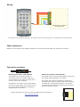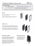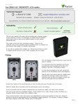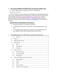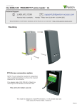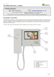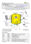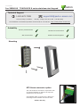
1
11/30/2011
Ins-30006-US
TOUCHLOCK K series stainless steel keypad
Paxton
Technical Support
1.800.672.7298
Technical help is available:
[email protected]
Monday - Friday from 02:00 AM - 8:00 PM (EST)
Documentation on all Paxton products can be found on our web site - http://www.paxton-access.com/
Suitability
Security sensitive doors
Mounted on metal surface
Wet environments
Readers mounted together
Mounting
K75 Screw connector option
The unit should be mounted in conjunction with
an electrical backbox to achieve the required
clearance for the connector.
If an adaptor plate (310-750-US) is fitted, the
mountings on the backbox can also be used.
Indoor use only
Wiring
Connection to a control
unit reader port
This product is not suitable for retail sale. All warranties are invalid if this product is not installed by a trained technician.
Cable extensions
Readers can be extended using Belden CR9538 8 core overall screened cable to a maximum of 500 feet.
Connection modules
Reader junction box (325-020-US)
This module can be used to provide a
connection point for the reader RJ45 plug.
The terminals on the module are then wired
color for color to the controller.
Alternatively, the reader can be wired directly
into the screw terminals of the control unit by
first cutting off the RJ45 plug and stripping
back the wires in the cable.
Reader Port Module (325-030-US)
This module may be purchased separately to speed up
the installing and replacement of readers.
The reader port module is designed to convert the
standard reader ports on Switch2 and Net2 controllers
to accept one or two RJ45 connections. Pull off the
screw terminal block from the reader port and simply
replace it with this module.
Further information on how to purchase Installer Tools is available at:
http://paxton.info/841
Technical Help
Here is the list of topics about this product that receive the most technical support inquiries.
We list them here to help you speed up the installation and trouble shooting process.
1 - Net2 - Bell function.
QPressing the bell button on the keypad will result in Relay 2 being energised for 1 second. A bell sounder can be
Qcontrolled by wiring one of the bell feeds across COM / NO on the relay.
2 - Switch2 - Initialising with 2 keypads.
QEither Keypad can be used to initialise the controller. Connect all wires in parallel, colour for colour.
3 - Switch2 (White label) & Touchlock Switch Control (922-177).
QThis keypad style does NOT work with these control units.
4 - Duress Codes.
QNet2 - Duress codes cannot be programmed into Net2.
QSwitch2 - These systems can accept Duress codes.
5 - Net2 - Replacing an old style keypad. (ACU Keypad port).
QWhen using this keypad with Net2, the software version used must be V3.21 or later and the keypad must be
Qwired into the standard reader port.
Specifications
Electrical
Voltage
Max
Min
8V DC
Current
14V DC
100 mA
Clock and data bit period
600 µs
No
Backlight
Environment
Operating temperatures - all items
Waterproof - Fixed cable
Max
Min
- 35 °C (- 31 °F)
+ 66 °C
(+ 151 °F)
IPX7
Outdoor use
Indoor use
Waterproof - K75 - Screw connection
Cable length
15 feet
Width
Height
K38
1 1/2 inch
3 inch
1/2
inch
K50
2 inch
4 inch
5/8
inch
K75
3 inch
5 1/2 inch
5/8
inch
Dimensions
Depth
FCC Compliance
Class B digital devices.
This equipment has been tested and found to comply with the limits for a Class B digital device, pursuant to Part 15 of the
FCC Rules. These limits are designed to provide reasonable protection against harmful interference in a residential installation.
This equipment generates, uses and can radiate radio frequency energy and, if not installed and used in accordance with the
instructions, may cause harmful interference to radio communications. However, there is no guarantee that interference will
not occur in a particular installation. If this equipment does cause harmful interference to radio or television reception, which
can be determined by turning the equipment off and on, the user is encouraged to try to correct the interference by one or
more of the following measures:
-- Reorient or relocate the receiving antenna.
-- Increase the separation between the equipment and receiver.
-- Connect the equipment into an outlet on a circuit different from that to which the receiver is connected.
-- Consult the dealer or an experienced radio/TV technician for help.
Class A digital devices.
This equipment has been tested and found to comply with the limits for a Class A digital device, pursuant to part 15 of the
FCC Rules. These limits are designed to provide reasonable protection against harmful interference when the equipment is
operated in a commercial environment. This equipment generates, uses, and can radiate radio energy and, if not installed and
used in accordance with the instruction manual, may cause harmful interference to radio communications. Operation of this
equipment in a residential area is likely to cause harmful interference in which case the user will be required to correct the
interference at his own expense.