1
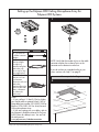
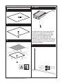
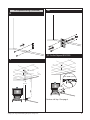
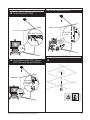
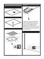
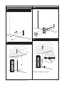
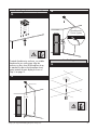
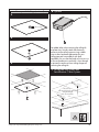
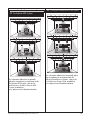
Setting Up the Polycom® HDX™
Ceiling Microphone Array Series
•If you are setting up a Polycom HDX Ceiling Microphone Array with a Polycom HDX
system, begin on page 2.
•If you are setting up a Polycom HDX Ceiling Microphone Array with a Polycom
SoundStructure™ C-Series system, begin on page 8.
•If you are setting up a Polycom HDX Ceiling Microphone Array Extension Kit with a
Polycom HDX or SoundStructure C-Series, begin on page 13.
•If you are setting up a Polycom RPX™ or TPX® telepresence system, refer to the RPX or TPX
Installation Guide.
Before you begin, make sure that your ceiling can support up to 2 lbs (.9 kg). Also,
verify that the installation parameters described in this document comply with the
code requirements in your local jurisdiction.
www.polycom.com
©2010, Polycom, Inc. All rights reserved. Polycom®, the Polycom logo, and TPX® are registered
trademarks and HDX™, SoundStructure™, and RPX™ are trademarks of Polycom, Inc.
January 2010
1725-27017-005/A
Setting up the Polycom HDX Ceiling Microphone Array for
Polycom HDX Systems
1
2’ (.6 m)
18” (.5 m) RJ-45
to Walta connector
adapter
10’ (3.1 m) nonplenum straightthrough (use
between wall plate
and codec only;
do not use for any
other application)
50’ (15.2 m)
plenum crossover
(use between
electronics enclosure
and codec,
between electronics
enclosure and wall
plate, or between
two electronics
enclosures)
NOTE: Verify that the number of pins on the cable
connector matches the number of pins on the
connector on the electronics enclosure.
If you do not have a suspended ceiling in your
room, continue with Step 12 on page 5.
For suspended ceilings
2
Notes:
• If your ceiling is 10 feet (3.05 m) or higher,
you should order an optional 6-foot (1.82 m)
drop cable (part number 2215-09591-002 for
black or 2215-09591-001 for white) for each
Ceiling Microphone Array.
• If you are creating your own cables, refer to
the Integrator’s Reference Manual for Polycom
HDX Systems for cable pin-outs. You can find
this document at
www.polycom.com/videodocumentation.
Setting up the Polycom HDX Ceiling Microphone Array Series
2
For suspended ceilings (continued)
6 Optional
3
.75” (1.9 cm)
4
5
For added safety when removing the ceiling tile
at a later time, securely attach the electronics
enclosure to the ceiling supports using suitable
wire or other hardware appropriate for your
ceiling type and in accordance with local
regulations. Be sure that the length of wire you use
to secure the electronics enclosure is short enough
to prevent the enclosure from striking the person
removing the ceiling tile.
7
.25”(.64 cm)
1.625”(4.13 cm)
.25”(.64 cm)
Setting up the Polycom HDX Ceiling Microphone Array Series
1.614”(4.10 cm)
1.614”(4.10 cm)
3
For suspended ceilings (continued)
10
8
11 For the Polycom HDX 9000
9
50’ (15.2 m)
HDX 9000 Systems
~ 10’
(3.1 m)
10’ (3.1 m)
Continue with Step 15 on page 6.
Setting up the Polycom HDX Ceiling Microphone Array Series
4
For suspended ceilings (continued)
11 For the Polycom HDX 8000, Polycom
HDX 7000, and Polycom HDX 6000
4
AUX
3 VCR/DVD
3 VCR/DVD
RJ-45
to Walta
connector
adapter
12
4
HDX 8000
HDX 7000
HDX 6000
Systems
For ceilings that are not suspended
10’ (3.1 m)
Continue with Step 15 on page 6.
11 For the Polycom HDX 4000
To attach the electronics enclosure, use suitable
hardware for your ceiling type. Align the
enclosure so that, when the Microphone Array
is attached, the dot on the Microphone Array
points towards the main display as shown in
Step 16 on page 7.
13
50’ (15.2 m)
HDX 4000
Systems
100-240VAC 50/60Hz 2.3A
RJ-45
to Walta
connector
adapter
~ 10’
(3.1 m)
10’ (3.1 m)
Continue with Step 15 on page 6.
Setting up the Polycom HDX Ceiling Microphone Array Series
5
For ceilings that are not suspended (cont.)
14 For the Polycom HDX 4000
14 For the Polycom HDX 9000
HDX 4000
Systems
HDX 9000 Systems
100-240VAC 50/60Hz 2.3A
RJ-45
to Walta
connector
adapter
For all ceilings
14 For the Polycom HDX 8000, Polycom
HDX 7000, and Polycom HDX 6000
4
4
AUX
3 VCR/DVD
3 VCR/DVD
HDX 8000
HDX 7000
HDX 6000
Systems
15
RJ-45
to Walta
connector
adapter
Setting up the Polycom HDX Ceiling Microphone Array Series
6
For all ceilings (cont.)
17
16
These systems...
You must point the dot (located on the band
around the middle of the microphone ball)
towards the main display.
Support up to this
many Ceiling Microphone Arrays...
Polycom HDX 9000 Series Four
Polycom HDX 8000 Series Three
Polycom HDX 7000 Series Two
Polycom HDX 6000 Series One
Polycom HDX 4000 Series Three
If you are planning to install another Ceiling
Microphone Array in the same room,
refer to Setting up the Ceiling Microphone
Array Extension Kit for Polycom HDX and
SoundStructure C-Series Systems on page 13.
For information about how to optimally
place the microphones to send stereo audio
for Polycom HDX Systems, refer to the
Administrator’s Guide for Polycom HDX
Systems, available at
www.polycom.com/videodocumentation.
Setting up the Polycom HDX Ceiling Microphone Array Series
7
Setting up the Polycom HDX Ceiling Microphone Array for
SoundStructure C-Series Systems
1
2’ (.6 m)
18” (.5 m) RJ-45
to Walta connector
adapter
10’ (3.1 m) nonplenum straightthrough (use
between wall plate
and codec only;
do not use for any
other application)
50’ (15.2 m)
plenum crossover
(use between
electronics enclosure
and codec,
between electronics
enclosure and wall
plate, or between
two electronics
enclosures)
NOTE: Verify that the number of pins on the cable
connector matches the number of pins on the
connector on the electronics enclosure.
If you do not have a suspended ceiling in your
room, continue with Step 12 on page 11.
For suspended ceilings
2
Notes:
• If your ceiling is 10 feet (3.05 m) or higher,
you should order an optional 6-foot (1.82 m)
drop cable (part number 2215-09591-002 for
black or 2215-09591-001 for white) for each
Ceiling Microphone Array.
• If you are creating your own cables, refer to
the Integrator’s Reference Manual for Polycom
HDX Systems for cable pin-outs. You can find
this document at
www.polycom.com/videodocumentation.
Setting up the Polycom HDX Ceiling Microphone Array Series
8
For suspended ceilings (continued)
6 Optional
3
.75” (1.9 cm)
4
5
For added safety when removing the ceiling tile
at a later time, securely attach the electronics
enclosure to the ceiling supports using suitable
wire or other hardware appropriate for your
ceiling type and in accordance with local
regulations. Be sure that the length of wire you use
to secure the electronics enclosure is short enough
to prevent the enclosure from striking the person
removing the ceiling tile.
7
.25”(.64 cm)
1.625”(4.13 cm)
.25”(.64 cm)
Setting up the Polycom HDX Ceiling Microphone Array Series
1.614”(4.10 cm)
1.614”(4.10 cm)
9
For suspended ceilings (continued)
10
8
11
9
50’ (15.2 m)
SoundStructure
C-Series Systems
RS-232
C-LINK2
IN
OBAM
OUT
IR 12V
1
2
3
4
5
6
7
8
9
10
11
12
13
14
15
16
1
2
3
4
5
6
7
8
9
10
11
12
13
14
15
16
REMOTE CONTROL 1
REMOTE CONTROL 2
INPUTS
LAN
OUTPUTS
PIN 2: TXD
PIN 3: RXD
PIN 5: GROUND
PIN 7: CTS
PIN 8: RTS
~ 10’
(3.1 m)
SoundStructureTM C16
C-LINK2
SoundStructure C16
TM
10’ (3.1 m)
SoundStructure C16
TM
Continue with Step 15 on page 11.
Setting up the Polycom HDX Ceiling Microphone Array Series
10
For ceilings that are not suspended
14
12
SoundStructure
C-Series Systems
RS-232
IN
OBAM
OUT
IR 12V
1
2
3
4
5
6
7
8
9
10
11
12
13
14
15
16
1
2
3
4
5
6
7
8
9
10
11
12
13
14
15
16
REMOTE CONTROL 1
REMOTE CONTROL 2
INPUTS
C-LINK2
OUTPUTS
PIN 2: TXD
PIN 3: RXD
PIN 5: GROUND
PIN 7: CTS
PIN 8: RTS
LAN
SoundStructureTM C16
C-LINK2
SoundStructure C16
TM
To attach the electronics enclosure, use suitable
hardware for your ceiling type. Align the
enclosure so that, when the Microphone Array
is attached, the dot on the Microphone Array
points towards the main display as shown in
Step 16 on page 12.
For all ceilings
15
13
50’ (15.2 m)
~ 10’
(3.1 m)
SoundStructure C16
TM
Setting up the Polycom HDX Ceiling Microphone Array Series
11
For all ceilings (continued)
17
16
These systems...
For Polycom SoundStructure C-Series Systems
that are being used with a video conferencing
system: You must point the dot (located on the
band around the middle of the microphone
ball) towards the main display.
For Polycom SoundStructure C-Series
Systems that are not being used with a video
conferencing system: You must point the dot
(located on the band around the middle of
the microphone ball) towards the front of the
room.
Setting up the Polycom HDX Ceiling Microphone Array Series
Support up to this
many Ceiling Microphone Arrays...
Polycom SoundStructure
C12 and C16
Four
Polycom SoundStructure
C8
Two
If you are planning to install another Ceiling
Microphone Array in the same room, refer to
Setting up the Polycom Ceiling Microphone
Array Extension Kit for Polycom HDX and
SoundStructure C-Series on page 13.
For information about how to optimally place
the microphones to send stereo audio for
Polycom SoundStructure Systems, refer to the
SoundStructure Design Guide, available at
www.polycom.com/voicedocumentation.
12
Setting up the Polycom HDX Ceiling Microphone Array Extension Kit for Polycom HDX and SoundStructure C-Series Systems
1
2’ (.6 m)
25’ (7.6 m) plenum
crossover
(use between two
electronics
enclosures)
Second 25’
(7.6 m) plenum
crossover
(use between
second and third
electronics
enclosures for TPX
HD 306M, Version
2.0 and later only)
Notes:
• If your ceiling is 10 feet (3.05 m) or higher,
you should order an optional 6-foot (1.82 m)
drop cable (part number 2215-09591-002 for
black or 2215-09591-001 for white) for each
Ceiling Microphone Array.
• If you are creating your own cables, refer to
the Integrator’s Reference Manual for Polycom
HDX Systems for cable pin-outs. You can find
this document at
www.polycom.com/videodocumentation.
Setting up the Polycom HDX Ceiling Microphone Array Series
NOTE: Verify that the number of pins on the cable
connector matches the number of pins on the
connector on the electronics enclosure.
If you do not have a suspended ceiling in your
room, continue with Step 8 on page 15.
For suspended ceilings
2
13
For suspended ceilings (continued)
6 Optional
3
.75” (1.9 cm)
4
5
For added safety when removing the ceiling tile
at a later time, securely attach the electronics
enclosure to the ceiling supports using suitable
wire or other hardware appropriate for your
ceiling type and in accordance with local
regulations. Be sure that the length of wire you use
to secure the electronics enclosure is short enough
to prevent the enclosure from striking the person
removing the ceiling tile.
7 For Polycom HDX Systems and
SoundStructure C-Series Systems
25’ (7.6 m)
(Do not use the non-plenum
straight-through
10 ‘ (3.1 m) cable)
Setting up the Polycom HDX Ceiling Microphone Array Series
14
For ceilings that are not suspended
10
8
For Polycom HDX: You must point the dot
(located on the band around the middle of the
microphone ball) towards the main display.
To attach the electronics enclosure, use suitable
hardware for your ceiling type. Align the
enclosure so that, when the Microphone Array
is attached, the dot on the Microphone Array
points towards the main display as shown in
Step 10 on this page.
For all ceilings
9
Setting up the Polycom HDX Ceiling Microphone Array Series
For Polycom SoundStructure C-Series Systems
that are being used with a video conferencing
system: You must point the dot (located on the
band around the middle of the microphone ball)
towards the main display.
For Polycom SoundStructure C-Series Systems
that are not being used with a video conferencing
system: You must point the dot (located on the
band around the middle of the microphone ball)
towards the front of the room.
15
For all ceilings (continued)
11 For Polycom SoundStructure C-Series Systems
11 For Polycom HDX Systems
For information about how to optimally
place the microphones to send stereo audio
for Polycom HDX Systems, refer to the
Administrator’s Guide for Polycom HDX
Systems, available at
www.polycom.com/videodocumentation.
Setting up the Polycom HDX Ceiling Microphone Array Series
For information abaout how to optimally place
the microphones to send stereo audio for
Polycom SoundStructure Systems, refer to the
SoundStructure Design Guide, available at
www.polycom.com/voicedocumentation.
16