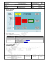
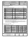
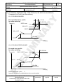
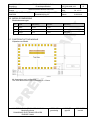
1
CLASSIFICATION
PRODUCT SPECIFICATION
Einstufung
Produktspezifikation
SUBJECT
Wireless M-Bus Module PAN7550
Thema
CUSTOMER PART NUMBER
PANASONIC PART NUMBER
PAN7550
ENW59620(2)xyCF
No.
REV.
DS-7550-0868-102
D
PAGE
Seite
1 of 27
DATE
13.03.2010
Datum
Specification for Production
Applicant / Manufacturer
Hardware
Panasonic Electronic Devices Europe GmbH
Zeppelinstrasse 19
21337 Lüneburg
Germany
Applicant / Manufacturer
Software
Wireless M-Bus Stack from ScatterWeb GmbH
your own written software
Software Version
Contents
Approval for Mass Production
or
Customer
By signing this document, Customer accepts the validity of the below-mentioned
contents and declares his full notice to it. Some passages may be changed if required;
the validity shall not be affected thereby.
CHECKED / APPROVED:
DATE:
NAME:
SIGNATURE:
NOTE:
AT LEAST ONE SET OF APPROVED SPECIFICATIONS SHOULD BE RETURNED TO
THE ADDRESS OF THE ISSUING PARTY.
HIGH FREQUENCY PRODUCTS DIVISION
Module Business
PANASONIC ELECTRONIC DEVICES
EUROPE GmbH
APPROVED
genehmigt
CHECKED
geprüft
DESIGNED
erstellt
CLASSIFICATION
PRODUCT SPECIFICATION
Einstufung
Produktspezifikation
SUBJECT
Wireless M-Bus Module PAN7550
Thema
CUSTOMER PART NUMBER
PANASONIC PART NUMBER
PAN7550
ENW59620(2)xyCF
No.
REV.
DS-7550-0868-102
D
PAGE
Seite
2 of 27
DATE
13.03.2010
Datum
TABLE OF CONTENTS
1.
2.
3.
4.
5.
6.
7.
8.
9.
10.
11.
12.
13.
14.
15.
16.
17.
18.
19.
20.
21.
22.
23.
24.
Key Features ...................................................................................................................4
Applications for the Module .............................................................................................4
Description of the Module................................................................................................5
Scope of this Document ..................................................................................................5
History for this Document ................................................................................................5
Terminal Layout...............................................................................................................6
Block Diagram .................................................................................................................9
Key Parts List ..................................................................................................................9
Test Conditions ...............................................................................................................9
Absolute Maximum Ratings...........................................................................................10
Operating Conditions.....................................................................................................10
DC Electrical Characteristics .........................................................................................11
A/D converter Characteristics........................................................................................11
AC Electrical Characteristics .........................................................................................12
Soldering Temperature - Time Profile (for reflow soldering) .........................................13
15.1. For lead solder .....................................................................................................13
15.2. For lead free solder ..............................................................................................13
Module DimensionS ......................................................................................................14
FootPrint of the Module .................................................................................................14
Labeling Drawing...........................................................................................................15
Mechanical Requirements .............................................................................................15
Recommended Land Pattern ........................................................................................16
Development of Applications .........................................................................................17
Reliability Tests .............................................................................................................17
Cautions ........................................................................................................................17
23.1. Design Notes .......................................................................................................17
23.2. Installation Notes .................................................................................................18
23.3. Usage Conditions Notes ......................................................................................18
23.4. Storage Notes ......................................................................................................19
23.5. Safety Cautions ....................................................................................................19
23.6. Other cautions ......................................................................................................19
Packaging......................................................................................................................21
24.1. Tape Dimension ...................................................................................................21
24.2. Packing in Tape ...................................................................................................21
24.3. Component direction ............................................................................................22
24.4. Label for Package ................................................................................................22
24.5. Reel Dimension ....................................................................................................23
24.6. Total Packing Handling ........................................................................................24
HIGH FREQUENCY PRODUCTS DIVISION
Module Business
PANASONIC ELECTRONIC DEVICES
EUROPE GmbH
APPROVED
genehmigt
CHECKED
geprüft
DESIGNED
erstellt
CLASSIFICATION
PRODUCT SPECIFICATION
Einstufung
Produktspezifikation
SUBJECT
Wireless M-Bus Module PAN7550
Thema
CUSTOMER PART NUMBER
PANASONIC PART NUMBER
PAN7550
ENW59620(2)xyCF
25.
26.
27.
28.
29.
30.
No.
REV.
DS-7550-0868-102
D
PAGE
Seite
3 of 27
DATE
13.03.2010
Datum
24.7. Cover tape reel strength ......................................................................................24
Ordering Information .....................................................................................................25
RoHS Declaration..........................................................................................................26
Data Sheet Status .........................................................................................................26
Related Documents .......................................................................................................26
General Information.......................................................................................................27
Life Support Policy ........................................................................................................27
HIGH FREQUENCY PRODUCTS DIVISION
Module Business
PANASONIC ELECTRONIC DEVICES
EUROPE GmbH
APPROVED
genehmigt
CHECKED
geprüft
DESIGNED
erstellt
CLASSIFICATION
PRODUCT SPECIFICATION
Einstufung
Produktspezifikation
SUBJECT
Wireless M-Bus Module PAN7550
Thema
CUSTOMER PART NUMBER
PANASONIC PART NUMBER
PAN7550
ENW59620(2)xyCF
1.
No.
REV.
DS-7550-0868-102
D
PAGE
Seite
4 of 27
DATE
13.03.2010
Datum
KEY FEATURES
Schlüsseleigenschaften
•
General Features
o
o
o
o
o
o
o
o
o
o
o
o
o
Small Size (13.7 mm x 32.0 mm x 2.85 mm)
Temperature Range from -40°C to +85°C
Supply Voltage Range from 1.8 V to 3.6 V
Very low Current Consumption for increased Battery Life
Additional 64k internal SPI EEPROM
UART and SPI Bus
3 Antenna Options: Internal Ceramic Antenna, UFL Plug, Single Port 50 Ohm
32kByte + 256Byte Flash and 1kByte RAM Memory
IrDA Encoder and Decoder
Configurable Operational Amplifier
Brownout Detector
Bootstrap Loader
12 channel 10 Bit A/D Converter with internal Reference
Sample-and-Hold, Autoscan, and Data Transfer Controller
o
o
•
2 x 16 Bit Timers with Capture/Compare Registers
In total 27 digital I/O lines with programmable pullup / pulldown resistors
RF Features
o
o
o
o
o
o
Programmable Data Rate from 1.2 to 500 kBaud (NRZ mode)
High Sensitivity -109 typ. at 1% PER and 1.2 kbps
Programmable Output Power from +10 to -30 dBm
Full 128-bit Encryption
Very Low Power Modes
Support for 2-FSK, GFSK, MSK, OOK and ASK
o Programmable Carrier Sense (CS) Indicator, Preamble Quality Indicator (PQI),
Link Quality Indicator (LQI) and Clear Channel Assessment (CCA)
2.
APPLICATIONS FOR THE MODULE
Anwendungen für das Modul
•
•
•
•
•
•
•
•
AMR- Automatic Meter Reading
Medical Applications
Wireless Sensors
Industrial Applications
RKE - Two-way Remote Keyless Entry
Remote Control Systems
Automotive Applications
Home Automation Systems
HIGH FREQUENCY PRODUCTS DIVISION
Module Business
PANASONIC ELECTRONIC DEVICES
EUROPE GmbH
APPROVED
genehmigt
CHECKED
geprüft
DESIGNED
erstellt
CLASSIFICATION
PRODUCT SPECIFICATION
Einstufung
Produktspezifikation
SUBJECT
Wireless M-Bus Module PAN7550
Thema
CUSTOMER PART NUMBER
PANASONIC PART NUMBER
PAN7550
ENW59620(2)xyCF
3.
No.
REV.
DS-7550-0868-102
D
PAGE
Seite
5 of 27
DATE
13.03.2010
Datum
DESCRIPTION OF THE MODULE
Beschreibung des Moduls
The PAN7550 module is a short range, low power, 868 MHz ISM band modem which is mainly
intended for Wireless M-Bus applications regarding to the EN 13757-4 standard. It includes a
very low power microcontroller (MCU) based on the MSP430 family and a low power RF
transceiver from Texas Instruments. This combination provides cost effective solutions for short
range data links and wireless networks.
The module is offered with an internal ceramic chip antenna, an UFL plug or a 50 ohm single
port on the bottom side of the module.
The main software solution for the PAN7550 is the Wireless M-Bus Stack from ScatterWeb
GmbH. For details please refer to [1]. In addition you are also free to develop your own software
by using any software development solution for the mentioned microcontroller. For device flash
programming you are able to use two different interfaces, the JTAG interface or the Spy-Bi-Wire
interface.
An application kit is also available for fast prototyping and application evaluation. For details
please refer to [3].
4.
SCOPE OF THIS DOCUMENT
Umfang dieses Dokumentes
This product specification applies to the Wireless M-Bus Module ENW59620(2)xyCF.
The xy is the indicator for different versions (refer to chapter 25 Ordering Information).
The used platform is the microcontroller MSP430F2274 in combination with the transceiver
CC1101 from the Texas Instruments www.ti.com/. For details please refer to [4], [5] and [6].
5.
HISTORY FOR THIS DOCUMENT
Versionsverwaltung dieses Dokumentes
Revision
Version
Date
Datum
Modification / Remarks
Änderungen / Bemerkungen
A
29.06.2009
Initial draft version
B
30.07.2009
C
16.02.2010
D
13.03.2010
Update chapter Block Diagram, EEPROM now optional.
Added values for chapter Absolute Maximum Ratings, Operating Conditions, DC
Electrical Characteristics and AC Electrical Characteristics
Correct some incorrect links.
Correct the Ordering Information. Updated chapter Development of Applications,
Packaging and Related Documents.
Add new ordering codes, which includes the EEPROM version, modification in
chapter Ordering Information.
HIGH FREQUENCY PRODUCTS DIVISION
Module Business
PANASONIC ELECTRONIC DEVICES
EUROPE GmbH
APPROVED
genehmigt
CHECKED
geprüft
DESIGNED
erstellt
CLASSIFICATION
PRODUCT SPECIFICATION
Einstufung
Produktspezifikation
SUBJECT
Wireless M-Bus Module PAN7550
Thema
CUSTOMER PART NUMBER
PANASONIC PART NUMBER
PAN7550
ENW59620(2)xyCF
6.
No.
REV.
DS-7550-0868-102
D
PAGE
Seite
6 of 27
DATE
13.03.2010
Datum
TERMINAL LAYOUT
Anschlußbelegung
Please refer also to the MSP430F2274 technical data sheet and reference manual, which is
given in [4] and [5] in the chapter Related Documents.
Pin
No.
1
2
Pin
Name
GND
VCC
Pin
Type
PWR
PWR
3
P2.0
I/O
4
P2.1
I/O
5
P2.2
I/O
6
P3.0
I/O
7
SPI SI
I/O
8
SPI SO
I/O
9
SPI SCLK
I/O
Description
Ground
Supply Voltage
General-purpose digital I/O pin / ACLK output
ADC10, analog input A0 / OA0, analog input I0
General-purpose digital I/O pin / Timer_A, clock signal at INCLK
SMCLK signal output
ADC10, analog input A1 / OA0, analog output
General-purpose digital I/O pin
Timer_A, capture: CCI0B input/BSL receive, compare: OUT0 output
ADC10, analog input A2 / OA0, analog input I1
General-purpose digital I/O pin
USCI_B0 slave transmit enable / USCI_A0 clock input/output
ADC10, analog input A5
General-purpose digital I/O pin
USCI_B0 slave in/master out in SPI mode
General-purpose digital I/O pin
USCI_B0 slave out/master in in SPI mode
General-purpose digital I/O pin
USCI_B0 clock input/output / USCI_A0 slave transmit enable
HIGH FREQUENCY PRODUCTS DIVISION
Module Business
PANASONIC ELECTRONIC DEVICES
EUROPE GmbH
APPROVED
genehmigt
CHECKED
geprüft
DESIGNED
erstellt
CLASSIFICATION
PRODUCT SPECIFICATION
Einstufung
Produktspezifikation
SUBJECT
Wireless M-Bus Module PAN7550
Thema
CUSTOMER PART NUMBER
PANASONIC PART NUMBER
PAN7550
ENW59620(2)xyCF
Pin
No.
Pin
Name
Pin
Type
10
P4.3
I/O
11
P4.4
I/O
12
13
GND
ANT
PWR
RF
14
P4.5
I/O
15
P4.6
I/O
16
P4.7
I/O
17
P3.6
I/O
18
P3.7
I/O
19
GND
PWR
20
P2.3
I/O
21
P2.4
I/O
22
P1.0
I/O
23
P1.1
I/O
24
P4.1
I/O
25
P4.2
I/O
26
TXD
I/O
27
RXD
I/O
28
N/C
---
29
P1.4
I/O
30
GND
PWR
31
P1.5
I/O
32
P1.6
I/O
No.
REV.
DS-7550-0868-102
D
PAGE
Seite
7 of 27
DATE
13.03.2010
Datum
Description
General-purpose digital I/O pin
Timer_B, capture: CCI0B input, compare: OUT0 output
ADC10 analog input A12 / OA0 analog output
General-purpose digital I/O pin
Timer_B, capture: CCI1B input, compare: OUT1 output
ADC10 analog input A13 / OA1 analog output
Ground
Pin for external antenna (50 Ω)
General-purpose digital I/O pin
Timer_B, compare: OUT2 output
ADC10 analog input A14 / OA0 analog input I3
General-purpose digital I/O pin
Timer_B, switch all TB0 to TB3 outputs to high impedance
ADC10 analog input A15 / OA1 analog input I3
General-purpose digital I/O pin
Timer_B, clock signal TBCLK input
General-purpose digital I/O pin
ADC10 analog input A6 / OA0 analog input I2
General-purpose digital I/O pin
ADC10 analog input A7 / OA1 analog input I2
Ground
General-purpose digital I/O pin
Timer_A, capture CCI1B input, compare: OUT1 output
ADC10, analog input A3 / negative reference voltage output/input
OA1, analog input I1 / OA1, analog output
General-purpose digital I/O pin / Timer_A, compare: OUT2 output
ADC10, analog input A4 / positive reference voltage output/input
OA1, analog input I0
General-purpose digital I/O pin
Timer_A, clock signal TACLK input
ADC10, conversion clock
General-purpose digital I/O pin
Timer_A, capture: CCI0A input, compare: OUT0 output/BSL transmit
General-purpose digital I/O pin
Timer_B, capture: CCI1A input, compare: OUT1 output
General-purpose digital I/O pin
Timer_B, capture: CCI2A input, compare: OUT2 output
General-purpose digital I/O pin
USCI_A0 transmit data output inUARTmode, slave in/master out in SPImode
General-purpose digital I/O pin
USCI_A0 receive data input in UART mode, slave out/master in in SPI mode
Not Connected
General-purpose digital I/O pin / SMCLK signal output
Test Clock input for device programming and test
Ground
General-purpose digital I/O pin / Timer_A, compare: OUT0 output
Test Mode Select input for device programming and test
General-purpose digital I/O pin / Timer_A, compare: OUT1 output
Test Data Input or Test Clock Input for programming and test
HIGH FREQUENCY PRODUCTS DIVISION
Module Business
PANASONIC ELECTRONIC DEVICES
EUROPE GmbH
APPROVED
genehmigt
CHECKED
geprüft
DESIGNED
erstellt
CLASSIFICATION
PRODUCT SPECIFICATION
Einstufung
Produktspezifikation
SUBJECT
Wireless M-Bus Module PAN7550
Thema
CUSTOMER PART NUMBER
PANASONIC PART NUMBER
PAN7550
ENW59620(2)xyCF
Pin
No.
Pin
Name
Pin
Type
33
P1.7
I/O
34
TEST
I/O
35
RST
I/O
36
P2.5
I/O
No.
REV.
DS-7550-0868-102
D
PAGE
Seite
8 of 27
DATE
13.03.2010
Datum
Description
General-purpose digital I/O pin / Timer_A, compare: OUT2 output
Test Data Output or Test Data Input for programming and test
Selects test mode for JTAG pins on Port1. The device protection fuse
is connected to TEST.
Spy-Bi-Wire test clock input during programming and test
Reset or nonmaskable interrupt input
Spy-Bi-Wire test data input/output during programming and test
General-purpose digital I/O pin
Input for external DCO resistor to define DCO frequency
HIGH FREQUENCY PRODUCTS DIVISION
Module Business
PANASONIC ELECTRONIC DEVICES
EUROPE GmbH
APPROVED
genehmigt
CHECKED
geprüft
DESIGNED
erstellt
CLASSIFICATION
PRODUCT SPECIFICATION
Einstufung
Produktspezifikation
SUBJECT
Wireless M-Bus Module PAN7550
Thema
CUSTOMER PART NUMBER
PANASONIC PART NUMBER
PAN7550
ENW59620(2)xyCF
7.
BLOCK DIAGRAM
Blockdiagramm
8.
KEY PARTS LIST
Liste der Schlüsselkomponenten
Part Name
Teilenummer
Material
Material
PCB
Casing
Glass cloth epoxide resin with gold plating
Material: ZSNC S1S8 8/8, thickness 0.30mm
MSP430F2274 (Texas Instruments www.ti.com/)
All information are based on [4] chapter 28.
CC1101 (Texas Instruments www.ti.com/)
All information are based on [6] chapter 28.
IC part name
9.
No.
REV.
DS-7550-0868-102
D
PAGE
Seite
9 of 27
DATE
13.03.2010
Datum
TEST CONDITIONS
Meßbedingungen
Measurements are made under room temperature and humidity unless otherwise specified.
Messungen unter normalen Bedingungen, Abweichungen sind gesondert notiert.
Temperature
Temperatur
25 ± 10°C
25 ± 10°C
Humidity
Luftfeuchtigkeit
HIGH FREQUENCY PRODUCTS DIVISION
Module Business
PANASONIC ELECTRONIC DEVICES
EUROPE GmbH
40 to 85%RH
40 to 85%RH
APPROVED
genehmigt
CHECKED
geprüft
DESIGNED
erstellt
CLASSIFICATION
PRODUCT SPECIFICATION
Einstufung
Produktspezifikation
SUBJECT
Wireless M-Bus Module PAN7550
Thema
CUSTOMER PART NUMBER
PANASONIC PART NUMBER
PAN7550
ENW59620(2)xyCF
No.
REV.
DS-7550-0868-102
D
PAGE
Seite
10 of 27
DATE
13.03.2010
Datum
10. ABSOLUTE MAXIMUM RATINGS
Absolute Grenzwerte
The maximum ratings may not be exceeded under any circumstances (not even momentarily) as
permanent damage to the module will result.
No.
Item
Punkt
Symbol
Zeichen
Absolute Maximum Ratings
Absolute Grenzwerte
Unit
Einheit
1
Supply voltage
V CC
-0.3 to +3.9
Vdc
(2)
2
Ripple on V CC
Vcc rip
tbd
3
Digital input voltages
V in
-0.3 to V CC +0.3 (max 3.9)
Vdc
4
Instantaneous maximum current
Single pin limit for all digital I/O
pins (1)
IB DB
±6
mAdc
5
Storage temperature range
T stg
-50 to +150
°C
6
Operating temperature range
T op
-40 to +85
°C
RF Input Power
P max
+10
dBm
V THHBM
750
V
T Death
Please refer to chapter 15.2.
°C
MSL
3 (168 hours)
7
8
9
10
ESD on any pin except for pin
13 ANT.
Human Body Model (HBM)
Lead temperature
Löttemperatur
Moisture Sensitivity Level
(ripple frequency ≥200kHz)
mVpp
Notes:
(1) The maximum total current for all digital I/O pins combined should not exceed ±48 mAdc to hold the
maximum voltage drop specified in [4].
(2) The supply voltage must be free of AC ripple voltage (for example from a battery or a low noise
regulator output). For noisy supply voltages, please provide a decoupling circuit (for example a ferrite
in series connection and a blocking capacitor to ground of at least 47µF directly at the module).
The exact ripple tolerance will be published in a later revision.
11. OPERATING CONDITIONS
Betriebsbedingungen
No.
Item
1
Supply voltage
2
RF Input Frequency
3
4
5
6
Return loss of load at pin 13
ANT
Positive-going input
threshold voltage
Negative-going input
threshold voltage
Input voltage hysteresis
Sym
bol
Condition / Remark
Value
Unit
Min
Typ
Max
V CC
1.8
3.0
3.6
Vdc
f in
868.0
868.3
870.0
MHz
A
-10
-
-
dB
for all digital I/O pins
V IT+
0.45xV CC
0.75xV CC
V
for all digital I/O pins
V IT-
0.25xV CC
0.55xV CC
V
for all digital I/O pins
V hys-
0.3
1.0
V
The typical value
is recommended
When using onboard
ceramic antenna
Receive/Transmit Mode to
50Ω reference load
HIGH FREQUENCY PRODUCTS DIVISION
Module Business
PANASONIC ELECTRONIC DEVICES
EUROPE GmbH
APPROVED
genehmigt
CHECKED
geprüft
DESIGNED
erstellt
CLASSIFICATION
PRODUCT SPECIFICATION
Einstufung
Produktspezifikation
SUBJECT
Wireless M-Bus Module PAN7550
Thema
CUSTOMER PART NUMBER
PANASONIC PART NUMBER
PAN7550
ENW59620(2)xyCF
No.
Item
7
Operating temperature
range
No.
REV.
DS-7550-0868-102
D
PAGE
Seite
11 of 27
DATE
13.03.2010
Datum
Sym
bol
Condition / Remark
Value
T op
Unit
Min
Typ
Max
-40
+25
+85
°C
12. DC ELECTRICAL CHARACTERISTICS
Assume V CC = 3.0V, T amb = 25°C if nothing else stated
No.
1
2
3
4
5
6
Item
Transmit current consumption
Receive current consumption
Low power current
consumption
digital I/O pin characteristics
digital I/O pin input capacitance
Low voltage warning/detection
Power on reset re-arm voltage
Condition / Remark
Symbol
Value
Min
Transmit Mode @ 10dBm
I CCT
Receive Mode
I CCR
Sleep (µC LPM 3)
I CCS
Stand by (Idle, µC activ)
I CCI
Please refer to [4] MCU Electrical Characteristics
all non-supply pins
C In
Unit
Typ
32
19
0,6
2
Max
-
mA
mA
µA
mA
5
pF
Please refer to [4] MCU Electrical Characteristics
13. A/D CONVERTER CHARACTERISTICS
No
Item
Remark
1
A/D characteristics
Please refer to [4] MCU Electrical Characteristics
2
A/D timing/performance
characteristics
Please refer to [4] MCU Electrical Characteristics
The A/D negative reference voltage VREF- is connected to pin 20 (P2.3)
The A/D positive reference voltage VREF+ is connected to pin 21 (P2.4)
HIGH FREQUENCY PRODUCTS DIVISION
Module Business
PANASONIC ELECTRONIC DEVICES
EUROPE GmbH
APPROVED
genehmigt
CHECKED
geprüft
DESIGNED
erstellt
CLASSIFICATION
PRODUCT SPECIFICATION
Einstufung
Produktspezifikation
SUBJECT
Wireless M-Bus Module PAN7550
Thema
CUSTOMER PART NUMBER
PANASONIC PART NUMBER
PAN7550
ENW59620(2)xyCF
No.
REV.
DS-7550-0868-102
D
PAGE
Seite
12 of 27
DATE
13.03.2010
Datum
14. AC ELECTRICAL CHARACTERISTICS
V CC = 3.0V, T amb = 25°C, 50Ω load at ANT
No
Nr
Receiver
Empfänger
Limit
Min
Typ
Max
Unit
Einheit
1
Sensitivity @ 1.2kbps, 1% PER
-
-109
-
dBm
2
Saturation (maximum input power level)
-
-15
-
dBm
3
In-band Spurious Emission
-
-
-65
dBm
4
Spurious Emissions <1GHz
-
-66
-60
dBm
5
Spurious Emissions >1GHz
-
-66
-33
dBm
No
Nr
Transmitter
Sender
Limit
Min
Typ
Max
Unit
Einheit
1
Maximum Output Power (measured at pin 13 and UFL)
-
9
10
dBm
2
Minimum Output Power
-
-30
-
dBm
3
Power Control Range
-
40
-
dB
4
Over the Air Data Rate
-
-
500
kbps
harmonic @ +10dBm
-
-35
-33
dBm
6
3 harmonic @ +10dBm
-
-42
-33
dBm
7
Spurious Emissions <1GHz, except No 8 @ +10dBm
-
-60
-39
dBm
8
Spurious Emissions 470 MHz to 862 MHz @ +10dBm
-
-66
-57
dBm
9
Spurious Emissions >1GHz @ +10dBm
-
-
-33
dBm
No
Nr
1
2
Stand By (Idle) and Sleep Mode
In Bereitschaft und Stromsparmodus
Spurious Emissions <1GHz
Spurious Emissions >1GHz
Limit
Min
-
Max
-57
-33
Unit
Einheit
dBm
dBm
5
nd
2
rd
HIGH FREQUENCY PRODUCTS DIVISION
Module Business
PANASONIC ELECTRONIC DEVICES
EUROPE GmbH
APPROVED
genehmigt
Typ
-65
-65
CHECKED
geprüft
DESIGNED
erstellt
CLASSIFICATION
PRODUCT SPECIFICATION
Einstufung
Produktspezifikation
SUBJECT
Wireless M-Bus Module PAN7550
Thema
CUSTOMER PART NUMBER
PANASONIC PART NUMBER
PAN7550
ENW59620(2)xyCF
No.
REV.
DS-7550-0868-102
D
PAGE
Seite
13 of 27
DATE
13.03.2010
Datum
15. SOLDERING TEMPERATURE - TIME PROFILE (FOR REFLOW SOLDERING)
Temperatur-Zeit Profil für die Reflowlötung
15.1. FOR LEAD SOLDER
10 ±1s
Recommended temp. profile
for reflow soldering
30 +20/-10s
235°C max.
Temp.[°C]
220 ±5°C
200°C
150 ±10°C
90 ±30s
Time [s]
15.2. FOR LEAD FREE SOLDER
Our used temp. profile
for reflow soldering
Temp.[°C]
30 +20/-10s
230°C -250°C max.
220°C
150°C – 190°C
90 ±30s
Time [s]
Reflow permissible cycles:
2
Opposite side reflow is prohibited due to the module weight.
HIGH FREQUENCY PRODUCTS DIVISION
Module Business
PANASONIC ELECTRONIC DEVICES
EUROPE GmbH
APPROVED
genehmigt
CHECKED
geprüft
DESIGNED
erstellt
CLASSIFICATION
PRODUCT SPECIFICATION
Einstufung
Produktspezifikation
SUBJECT
Wireless M-Bus Module PAN7550
Thema
CUSTOMER PART NUMBER
PANASONIC PART NUMBER
PAN7550
ENW59620(2)xyCF
No.
REV.
DS-7550-0868-102
D
PAGE
Seite
14 of 27
DATE
13.03.2010
Datum
16. MODULE DIMENSIONS
Modulabmessungen
No.
Item
Punkt
Dimension
Abmessung
Tolerance
Toleranz
1
Width
13.70
± 0.20
2
Lenght
32.00
± 0.20
3
Height
2.45
± 0.10
Remark
Bemerkung
With case
17. FOOTPRINT OF THE MODULE
Lötpads vom Modul
All dimensions are in millimeters.
The outer dimensions have a tolerance of ± 0.2mm.
HIGH FREQUENCY PRODUCTS DIVISION
Module Business
PANASONIC ELECTRONIC DEVICES
EUROPE GmbH
APPROVED
genehmigt
CHECKED
geprüft
DESIGNED
erstellt
CLASSIFICATION
PRODUCT SPECIFICATION
Einstufung
Produktspezifikation
SUBJECT
Wireless M-Bus Module PAN7550
Thema
CUSTOMER PART NUMBER
PANASONIC PART NUMBER
PAN7550
ENW59620(2)xyCF
No.
REV.
DS-7550-0868-102
D
PAGE
Seite
15 of 27
DATE
13.03.2010
Datum
18. LABELING DRAWING
Kennzeichnung des Moduls durch Label
This label is suitable for reflow soldering and designed for the engineering sample status.
Information in the 2D-Barcode are the date code in the format Year-Month-Day [6 signs, here
081211], serial number [7 signs, here 0000000], ordering number [8 signs; without ENW and F,
please refer also to chapter 25], the identifier for the hardware release [2 signs, here yy], the
identifier for the software release [2 signs, here zz] and the ES, separated by a semicolon.
ES stands for Engineering Samples, please refer to chapter General Information.
In mass production status, the ES will be eliminated.
The point on the label (below left) is the identifier for pin 1 of the module.
As a summary:
xy
Number 9 and 10 from the ordering code, please refer to chapter 25
yy
Identifier for the hardware version
zz
Identifier for the software version
19. MECHANICAL REQUIREMENTS
Mechanische Anforderungen
No.
Item
Punkt
1
Solderability
Lötfähigkeit
2
Resistance to
soldering heat
Limit
Grenzwerte
More than 75% of the soldering area shall be
coated by solder
Mehr als 75% der Lötfläche soll mit Lötpaste
bedeckt sein.
Must satisfy electrical requirements and not
have mechanical damage
HIGH FREQUENCY PRODUCTS DIVISION
Module Business
PANASONIC ELECTRONIC DEVICES
EUROPE GmbH
APPROVED
genehmigt
Condition
Bedingung
Reflow soldering with
recommendable temperature
profile
Please refer to chapter 15.2.
CHECKED
geprüft
DESIGNED
erstellt
CLASSIFICATION
PRODUCT SPECIFICATION
Einstufung
Produktspezifikation
SUBJECT
Wireless M-Bus Module PAN7550
Thema
CUSTOMER PART NUMBER
PANASONIC PART NUMBER
PAN7550
ENW59620(2)xyCF
No.
REV.
DS-7550-0868-102
D
PAGE
Seite
16 of 27
DATE
13.03.2010
Datum
20. RECOMMENDED LAND PATTERN
Empfohlenes Land Pattern
Dimensions in millimeters.
The land pattern dimensions above are meant to serve only as a guid. This information is
provided without any legal liability.
For the footprint, it is recommended to incorporate a 50µm bigger size for the pads in each
direction compared to the module footprint. Please refer to chapter 17. Footprint of the Module.
For the solder paste screen, please use the same screen for the module. Solder paste screen
cutouts (with slightly different dimensions) might be optimum depending on your soldering
process For example, the chosen solder paste screen thickness might havean effect. The solder
screen thickness depends on your production standard. We recommend 120µm to 150µm.
IMPORTANT:
Although the bottom side of PAN7550 is fully coated, no copper such as through hole vias,
planes or tracks on the board component layer should be located below the PAN7550 to avoid
creating a short. In cases where a track or through hole via has to be located under the module,
please make a note that it has to be kept away from PAN7550 bottom pads. The PAN7550
multilayer pcb contains an inner RF shielding plane, therefore no pcb shielding plane below the
module is needed.
When using the antenna pad version, please place the antenna on the edge of your carrier
board (if allowable).
If you have any questions on these points, please contact your local Panasonic representative.
Before releasing the layout, we recommend to sent the schematic and layout for final check to
[email protected].
HIGH FREQUENCY PRODUCTS DIVISION
Module Business
PANASONIC ELECTRONIC DEVICES
EUROPE GmbH
APPROVED
genehmigt
CHECKED
geprüft
DESIGNED
erstellt
CLASSIFICATION
PRODUCT SPECIFICATION
Einstufung
Produktspezifikation
SUBJECT
Wireless M-Bus Module PAN7550
Thema
CUSTOMER PART NUMBER
PANASONIC PART NUMBER
PAN7550
ENW59620(2)xyCF
No.
REV.
DS-7550-0868-102
D
PAGE
Seite
17 of 27
DATE
13.03.2010
Datum
21. DEVELOPMENT OF APPLICATIONS
Please refer to [1], [2] and [3] in chapter 28. Related Documents.
22. RELIABILITY TESTS
Zuverlässigkeitstests
The measurement should be done after being exposed to room temperature and humidity for 1
hour.
Die Messungen sollten erst nach einer Stunde Lagerung unter normalen Bedingungen erfolgen.
No.
Item
Punkt
Limit
Grenzwerte
1
Vibration test
Electrical parameter should be
in specification
2
Shock test
the same as above
3
Heat cycle test
the same as above
4
5
6
Moisture test
Low temp. test
High temp. test
the same as above
the same as above
the same as above
Condition
Bedingung
a) Freq.:10~50Hz,Amplitude:1.5mm
a) 20min. / cycle,1hrs. each of XYZ axis
b) Freq.:30~100Hz, 6G
b) 20min. / cycle,1hrs. each of XYZ axis
Dropped onto hard wood from height of 50cm for
3 times
-40°C for 30min. and +85°C for 30min.;
each temperature 300 cycles
+60°C, 90% RH, 300h
-40°C, 300h
+85°C, 300h
23. CAUTIONS
Warnungen
Failure to do so may result in degrading of the product’s functions and damage to the product.
23.1. DESIGN NOTES
Designhinweise
(1)
(2)
(3)
(4)
(5)
(6)
Please follow the conditions written in this specification, especially the control
signals of this module.
The supply voltage has to be free of AC ripple voltage (for example from a
battery or a low noise regulator output). For noisy supply voltages, provide a
decoupling circuit (for example a ferrite in series connection and a blocking
capacitor to ground of at least 47uF directly at the module).
This product should not be mechanically stressed when installed.
Heat is the major cause of shortening the life of these products. Please keep this
product away from heat.
Avoid assembly and use of the target equipment in conditions where the
products' temperature may exceed the maximum tolerance.
The supply voltage should not be exceedingly high or reversed. It should not
carry noise and/or spikes.
Please keep this product away from other high frequency circuits.
HIGH FREQUENCY PRODUCTS DIVISION
Module Business
PANASONIC ELECTRONIC DEVICES
EUROPE GmbH
APPROVED
genehmigt
CHECKED
geprüft
DESIGNED
erstellt
CLASSIFICATION
PRODUCT SPECIFICATION
Einstufung
Produktspezifikation
SUBJECT
Wireless M-Bus Module PAN7550
Thema
CUSTOMER PART NUMBER
PANASONIC PART NUMBER
PAN7550
ENW59620(2)xyCF
No.
REV.
DS-7550-0868-102
D
PAGE
Seite
18 of 27
DATE
13.03.2010
Datum
23.2. INSTALLATION NOTES
Verarbeitungshinweise
(1)
(2)
(3)
(4)
(5)
(6)
(7)
(8)
(9)
Reflow soldering is possible twice based on the conditions in chapter 15.
Please set up the temperature at the soldering portion of this product according
to this reflow profile.
Carefully position the products so that their heat will not burn into printed circuit
boards or affect the other components that are susceptible to heat.
Carefully locate these products so that their temperatures will not increase due
to the effects of heat generated by neighboring components.
If a vinyl-covered wire comes into contact with the products, then the cover will
melt and generate toxic gas, damaging the insulation. Never allow contact
between the cover and these products to occur.
This product should not be mechanically stressed or vibrated when reflowed.
If you want to repair your board by hand soldering, please keep the conditions of
this chapter.
Please do not wash this product.
Please refer to the recommended pattern when designing a board.
Pressing on parts of the metal cover or fastening objects to the metal will cause
damage to the unit.
23.3. USAGE CONDITIONS NOTES
Benutzerhinweise
(1)
(2)
(3)
(4)
(5)
(6)
(7)
Please take measures to protect the unit against static electricity.
If pulses or other transient loads (a large load applied in a short time) are applied
to the products, check and evaluate their operation befor assembly on the final
products.
Please do not use dropped products.
Please do not touch, damage or place dirt on the pins.
Please follow the recommended condition ratings about the power supply
applied to this product.
Electrode peeling strength: Do not add pressure of more than 4.9N when
soldered on PCB.
Pressing on parts of the metal cover or fastening objects to the metal cover will
cause damage.
These products are intended for general purpose and standard use in general
electronic equipment, such as home appliances, office equipment, information
and communication equipment.
HIGH FREQUENCY PRODUCTS DIVISION
Module Business
PANASONIC ELECTRONIC DEVICES
EUROPE GmbH
APPROVED
genehmigt
CHECKED
geprüft
DESIGNED
erstellt
CLASSIFICATION
PRODUCT SPECIFICATION
Einstufung
Produktspezifikation
SUBJECT
Wireless M-Bus Module PAN7550
Thema
CUSTOMER PART NUMBER
PANASONIC PART NUMBER
PAN7550
ENW59620(2)xyCF
No.
REV.
DS-7550-0868-102
D
PAGE
Seite
19 of 27
DATE
13.03.2010
Datum
23.4. STORAGE NOTES
Lagerhinweise
(1)
(2)
(3)
(4)
(5)
(6)
The module may not be stressed mechanically during storage.
Do not store these products in the following conditions or the performance
characteristics of the product, such as RF performance will be adversely
affected:
• Storage in salty air or in an environment with a high concentration of corrosive
gas, such as Cl2, H2S, NH3, SO2, or NOX
• Storage in direct sunlight
• Storage in an environment where the temperature may be outside the range of
5°C to 35°C range, or where the humidity may be outside the 45 to 85% range.
• Storage of the products for more than one year after the date of delivery at your
company if the avoidance all the above conditions (1) to (3) have been met.
Storage period: Please check the adhesive strength of the embossed tape and
soldering after 6 months of storage.
Please keep this product away from water, poisonous gas and corrosive gas.
This product should not be stressed or shocked when transported.
Please follow the specification when stacking packed crates (max. 10).
23.5. SAFETY CAUTIONS
Sicherheitshinweise
These specifications are intended to preserve the quality assurance of products and
individual components.
Before use, check and evaluate the operation when mounted on your products. Abide by
these specifications, without deviation when using the products. These products may shortcircuit. If electrical shocks, smoke, fire, and/or accidents involving human life are
anticipated when a short circuit occurs, then provide the following failsafe functions, as a
minimum.
(1) Ensure the safety of the whole system by installing a protection circuit and a
protection device.
(2) Ensure the safety of the whole system by installing a redundant circuit or
another system to prevent a single fault causing an unsafe status.
23.6. OTHER CAUTIONS
Weitere Hinweise
(1)
(2)
(3)
(4)
(5)
This specification sheet is copyrighted. Please do not disclose it to a third party.
Please do not use the products for other purposes than those listed.
Be sure to provide an appropriate fail-safe function on your product to prevent
an additional damage that may be caused by the abnormal function or the failure
of the product.
This product has not been manufactured with any ozone chemical controlled
under the Montreal Protocol.
These products are not intended for other uses, other than under the special
conditions shown below. Before using these products under such special
conditions, check their performance and reliability under the said special
HIGH FREQUENCY PRODUCTS DIVISION
Module Business
PANASONIC ELECTRONIC DEVICES
EUROPE GmbH
APPROVED
genehmigt
CHECKED
geprüft
DESIGNED
erstellt
CLASSIFICATION
PRODUCT SPECIFICATION
Einstufung
Produktspezifikation
SUBJECT
Wireless M-Bus Module PAN7550
Thema
CUSTOMER PART NUMBER
PANASONIC PART NUMBER
PAN7550
ENW59620(2)xyCF
(6)
(7)
No.
REV.
DS-7550-0868-102
D
PAGE
Seite
20 of 27
DATE
13.03.2010
Datum
conditions carefully to determine whether or not they can be used in such a
manner.
• In liquid, such as water, salt water, oil, alkali, or organic solvent, or in places
where liquid may splash.
• In direct sunlight, outdoors, or in a dusty environment
• In an environment where condensation occurs.
• In an environment with a high concentration of harmful gas (e.g. salty air,
HCl, Cl2, SO2, H2S, NH3, and NOX)
If an abnormal voltage is applied due to a problem occurring in other
components or circuits, replace these products with new products because they
may not be able to provide normal performance even if their electronic
characteristics and appearances appear satisfactory.
When you have any question or uncertainty, both of you and Panasonic
sincerely cope with it.
HIGH FREQUENCY PRODUCTS DIVISION
Module Business
PANASONIC ELECTRONIC DEVICES
EUROPE GmbH
APPROVED
genehmigt
CHECKED
geprüft
DESIGNED
erstellt
CLASSIFICATION
PRODUCT SPECIFICATION
Einstufung
Produktspezifikation
SUBJECT
Wireless M-Bus Module PAN7550
Thema
CUSTOMER PART NUMBER
PANASONIC PART NUMBER
PAN7550
ENW59620(2)xyCF
No.
REV.
DS-7550-0868-102
D
PAGE
Seite
21 of 27
DATE
13.03.2010
Datum
24. PACKAGING
Verpackung
24.1. TAPE DIMENSION
12
Antenna
Top
View
000001
090622
1
01
01
19
01
01
000001
090622
ENW59620A1CF
PAN 7550 ES
30
100216-PAN7550.vsd
Antenna
12
1
30
ENW59620A1CF
PAN 7550 ES
19
100216-PAN7550.vsd
Top
View
24.2. PACKING IN TAPE
Empty spaces in component packed area shall be less than two per reel and those spaces
shall not be consecutive.
Top cover tape shall not be found on reel holes and shall not stick out from the reel.
HIGH FREQUENCY PRODUCTS DIVISION
Module Business
PANASONIC ELECTRONIC DEVICES
EUROPE GmbH
APPROVED
genehmigt
CHECKED
geprüft
DESIGNED
erstellt
CLASSIFICATION
PRODUCT SPECIFICATION
Einstufung
Produktspezifikation
SUBJECT
Wireless M-Bus Module PAN7550
Thema
CUSTOMER PART NUMBER
PANASONIC PART NUMBER
PAN7550
ENW59620(2)xyCF
No.
REV.
DS-7550-0868-102
D
PAGE
Seite
22 of 27
DATE
13.03.2010
Datum
24.3. COMPONENT DIRECTION
Komponentenanordnung
24.4. LABEL FOR PACKAGE
105 mm
PAN7550
Customer Code
(1T):
(1P)
(2P)
(9D)
(Q)
(HW/SW)
[[G]]
ENW59620xyCF
Lotcode [YYWWDLL]
YY
year
here 08
WW normal calendar week
here 01
D
day
here 5 (Friday)
L
line identifier, if more as one
here 1
L
lot identifier per day
e.g. 1, 2, 3…
Customer Code, if any, otherwise put company name on it.
Panasonic Order Code, refer to chapter 25.
Datecode as [YYWW]
Quantity, here 1000, can differ on customer request.
Hardware /Software Release, refer to chapter 25.
Identifier that the product is RoHS conform, please refer also to 26.
HIGH FREQUENCY PRODUCTS DIVISION
Module Business
PANASONIC ELECTRONIC DEVICES
EUROPE GmbH
APPROVED
genehmigt
CHECKED
geprüft
DESIGNED
erstellt
CLASSIFICATION
PRODUCT SPECIFICATION
Einstufung
Produktspezifikation
SUBJECT
Wireless M-Bus Module PAN7550
Thema
CUSTOMER PART NUMBER
PANASONIC PART NUMBER
PAN7550
ENW59620(2)xyCF
No.
REV.
DS-7550-0868-102
D
PAGE
Seite
23 of 27
DATE
13.03.2010
Datum
24.5. REEL DIMENSION
Due to tape width of 44mm, the reel width will be 52mm.
HIGH FREQUENCY PRODUCTS DIVISION
Module Business
PANASONIC ELECTRONIC DEVICES
EUROPE GmbH
APPROVED
genehmigt
CHECKED
geprüft
DESIGNED
erstellt
CLASSIFICATION
PRODUCT SPECIFICATION
Einstufung
Produktspezifikation
SUBJECT
Wireless M-Bus Module PAN7550
Thema
CUSTOMER PART NUMBER
PANASONIC PART NUMBER
PAN7550
ENW59620(2)xyCF
No.
REV.
DS-7550-0868-102
D
PAGE
Seite
24 of 27
DATE
13.03.2010
Datum
24.6. TOTAL PACKING HANDLING
24.7. COVER TAPE REEL STRENGTH
Force direction
θ = 10deg
Speed = 300mm/min.
Cover tape reel strength
=0.098~0.68N (10~70g)
HIGH FREQUENCY PRODUCTS DIVISION
Module Business
PANASONIC ELECTRONIC DEVICES
EUROPE GmbH
APPROVED
genehmigt
CHECKED
geprüft
DESIGNED
erstellt
CLASSIFICATION
PRODUCT SPECIFICATION
Einstufung
Produktspezifikation
SUBJECT
Wireless M-Bus Module PAN7550
Thema
CUSTOMER PART NUMBER
PANASONIC PART NUMBER
PAN7550
ENW59620(2)xyCF
No.
REV.
DS-7550-0868-102
D
PAGE
Seite
25 of 27
DATE
13.03.2010
Datum
25. ORDERING INFORMATION
Bestellinformationen
MOQ (1)
No.
Ordering part number
Description
1
ENW5Z620A2CF (2)
2
ENW5Z620B2CF (2)
3
ENW5Z620C2CF (2)
4
ENW5Z620A1CF (2)
Same as number 1, but without Software
1
5
ENW5Z620B1CF (2)
Same as number 2, but without Software
1
6
ENW5Z620C1CF
(2)
Same as number 3, but without Software
1
7
ENW5Z622A2CF (2)
8
ENW5Z622B2CF (2)
9
ENW5Z622C2CF (2)
10
ENW5Z622A1CF (2)
Same as number 7, but without Software
1
11
ENW5Z622B1CF
(2)
Same as number 8, but without Software
1
12
ENW5Z622C1CF (2)
Same as number 9, but without Software
1
Engineering Sample PAN7550 (no EEPROM)
Wireless M-Bus Module, which includes Ceramic Antenna
Wireless M-Bus Stack from ScatterWeb included, please refer to [1].
Engineering Sample PAN7550 (no EEPROM)
Wireless M-Bus Module, which includes UFL Connector
Wireless M-Bus Stack from ScatterWeb included, please refer to [1].
Engineering Sample PAN7550 (no EEPROM)
Wireless M-Bus Module, which includes RF out on SMD pad
Wireless M-Bus Stack from ScatterWeb included, please refer to [1].
Engineering Sample PAN7550 (with EEPROM)
Wireless M-Bus Module, which includes Ceramic Antenna
Wireless M-Bus Stack from ScatterWeb included, please refer to [1].
Engineering Sample PAN7550 (with EEPROM)
Wireless M-Bus Module, which includes UFL Connector
Wireless M-Bus Stack from ScatterWeb included, please refer to [1]
Engineering Sample PAN7550 (with EEPROM)
Wireless M-Bus Module, which includes RF out on SMD pad
Wireless M-Bus Stack from ScatterWeb included, please refer to [1].
1
1
1
1
1
1
Note:
(1)
(2)
Minimum order quantity.
The “Z” in the ordering part number, refers to the engineering sample status. After mass production
the “Z” will be changed to the “9”.
HIGH FREQUENCY PRODUCTS DIVISION
Module Business
PANASONIC ELECTRONIC DEVICES
EUROPE GmbH
APPROVED
genehmigt
CHECKED
geprüft
DESIGNED
erstellt
CLASSIFICATION
PRODUCT SPECIFICATION
Einstufung
Produktspezifikation
SUBJECT
Wireless M-Bus Module PAN7550
Thema
CUSTOMER PART NUMBER
PANASONIC PART NUMBER
PAN7550
ENW59620(2)xyCF
No.
REV.
DS-7550-0868-102
D
PAGE
Seite
26 of 27
DATE
13.03.2010
Datum
26. ROHS DECLARATION
RoHS-Erklärung
Declaration of environmental compatibility for supplied products:
Hereby we declare to our best present knowledge based on declaration of our suppliers that this
product does not contain the following substances which are banned by Directive 2002/95/EC
(RoHS) or contains a maximum concentration of 0.1% by weight in homogeneous materials for
•
•
•
•
•
Lead and lead compounds
Mercury and mercury compounds
Chromium (VI)
PBB (polybrominated biphenyl) category
PBDE (polybrominated biphenyl ether) category
And a maximum concentration of 0.01% by weight in homogeneous materials for
•
Cadmium and cadmium compounds
27. DATA SHEET STATUS
Datenblatt Status
This data sheet contains data from the PRELIMINARY specification. Supplementary data will be
published at a later date. Panasonic Electronic Devices Europe GmbH reserves the right to
change the specification without notice, in order to improve the design and supply the best
possible product.
Please consult the most recently issued data sheet before initiating or completing a design.
If there is an update, please download under: PAN7550 Latest Data Sheet!
28. RELATED DOCUMENTS
Mitgeltende Dokumente
For an update, please search in the suitable homepage.
[1]
User’s Guide to the Wireless M-Bus Stack, ScatterWeb GmbH [Download]
[2]
User’s Guide to the Wireless M-Bus Stack, company Steinbeis [Download]
[3]
Manual to the Application Kit from Panasonic [Download]
[4]
Datasheet MSP430F2274, Document Number: SLAS504B -- JULY 2006 – REVISED
JULY 2007, Texas Instruments
[5]
MSP430Fx2xx User Manual, Document Number: SLAU144E, Texas Instruments
[6]
CC1101 Datasheet, Document Number: SWRS061E -- April 2009 – REVISED April 2009,
Texas Instruments
HIGH FREQUENCY PRODUCTS DIVISION
Module Business
PANASONIC ELECTRONIC DEVICES
EUROPE GmbH
APPROVED
genehmigt
CHECKED
geprüft
DESIGNED
erstellt
CLASSIFICATION
PRODUCT SPECIFICATION
Einstufung
Produktspezifikation
SUBJECT
Wireless M-Bus Module PAN7550
Thema
CUSTOMER PART NUMBER
PANASONIC PART NUMBER
PAN7550
ENW59620(2)xyCF
No.
REV.
DS-7550-0868-102
D
PAGE
Seite
27 of 27
DATE
13.03.2010
Datum
29. GENERAL INFORMATION
Allgemeine Informationen
© Panasonic Electronic Devices Europe GmbH 2010.
All rights reserved.
This product description does not claim to be complete and free of mistakes.
Please contact the related product manager with any errata inquries.
If we deliver samples to the customer, these samples have the status Engineering Samples.
This means, the design of this product is not yet completed. Engineering Samples may be
partially or fully functional, and there may be differences published in the Data Sheet.
Engineering Samples are not qualified and are not to be used for reliability testing or series
production.
Disclaimer:
Customer acknowledges that samples may deviate from the Data Sheet and may bear defects
due to their status of development and the lack of qualification mentioned above.
Panasonic Electronic Devices Europe GmbH disclaims any liability or product warranty for
Engineering Samples. In particular, Panasonic Electronic Devices Europe GmbH disclaims
liability for damages caused by
• the use of the Engineering Sample other than for Evaluation Purposes, particularly the
installation or integration in an other product to be sold by Customer,
• deviation or lapse in function of Engineering Sample,
• improper use of Engineering Samples.
Panasonic Electronic Devices Europe GmbH disclaimes any liability for consequential and
incidental damages. In case of any questions, please contact your local sales partner or the
related product manager.
30. LIFE SUPPORT POLICY
Politik für Lebenserhaltungssysteme
This Panasonic Electronic Devices Europe GmbH product is not designed for use in life
support appliances, devices, or systems where malfunction can reasonably be expected to
result in a significant personal injury to the user, or as a critical component in any life support
device or system whose failure to perform can be reasonably expected to cause the failure of
the life support device or system, or to affect its safety or effectiveness. Customers using or
selling these products for use in such applications do so at their own risk and agree to fully
indemnify Panasonic Electronic Devices Europe GmbH for any damages resulting.
HIGH FREQUENCY PRODUCTS DIVISION
Module Business
PANASONIC ELECTRONIC DEVICES
EUROPE GmbH
APPROVED
genehmigt
CHECKED
geprüft
DESIGNED
erstellt