1
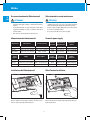
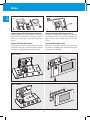
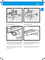
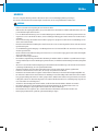
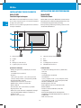
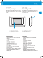
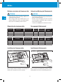
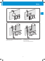
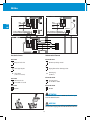
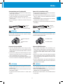
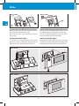
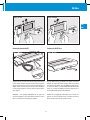
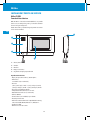
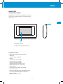
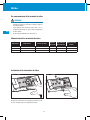
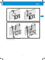
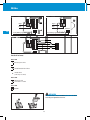
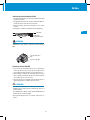
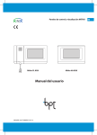
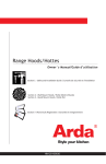
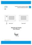
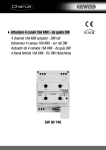
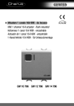
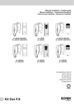
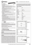
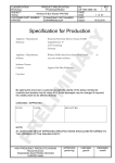
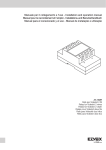
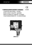
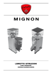
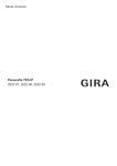
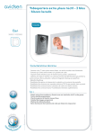
Pannelli di comando e visualizzazione MITHO Command and display panels MITHO Mitho PL KNX MithoKNX_TEC IT-EN 24807960 13-01-14 IT EN Panneaux de commande et visualisation MITHO Bedien- und Anzeigepaneele MITHO DE Paneles de control y visualización MITHO ES Mitho HA KNX FR Mitho AVVERTENZE IT EN Le informazioni contenute nel presente manuale sono soggette a modifiche senza preavviso. Il costruttore non assume alcuna responsabilità per gli eventuali errori che il presente documento può contenere. ATTENZIONE • • • • • • • • • • • • • • • • • • • • Dopo aver tolto l’imballaggio assicurarsi dell’integrità dell’apparecchio. Gli elementi dell’imballaggio (sacchetti in plastica, polistirolo espanso, ecc.) non devono essere lasciati alla portata dei bambini in quanto potenziali fonti di pericolo. Leggere attentamente le istruzioni, prima di iniziare l’installazione ed eseguire gli interventi come specificato dal costruttore. Prima di collegare l’apparecchio accertarsi che i dati di targa siano rispondenti a quelli della rete di distribuzione. A monte dell’apparecchio, sull’impianto elettrico dell’edificio, deve essere presente un interruttore di rete onnipolare con una separazione dei contatti di almeno 3 mm. Il costruttore non può essere considerato responsabile per eventuali danni derivanti da usi impropri, erronei ed irragionevoli. Prima di effettuare qualunque operazione di pulizia o di manutenzione, disinserire l’apparecchio dalla rete di alimentazione elettrica, aprendo l’interruttore dell’impianto. In caso di guasto e/o cattivo funzionamento dell’apparecchio, distaccarlo dall’alimentazione e non manometterlo. Utilizzare sempre ricambi originali. L’installazione, la programmazione, la messa in servizio e la manutenzione del prodotto deve essere effettuata soltanto da personale tecnico qualificato ed opportunamente addestrato nel rispetto delle normative vigenti ivi comprese le osservanze sulla prevenzione infortuni. Operare in ambienti sufficientemente illuminati e idonei per la salute e utilizzare strumenti, utensili ed attrezzature in buono stato. Al termine dell’installazione verificare sempre il corretto funzionamento dell’apparecchiatura e dell’impianto nel suo insieme. Non installare il dispositivo all’esterno o in luoghi dove sia sottoposto a stillicidio o a spruzzi d’acqua. Trattare con cura il dispositivo, contiene parti elettroniche fragili e sensibili all’umidità. Le schede elettroniche possono essere seriamente danneggiate dalle scariche elettrostatiche: qualora vi sia bisogno di maneggiarle indossare idonei indumenti e calzature anti statiche o, almeno, assicurarsi preventivamente di aver rimosso ogni carica residua toccando con la punta delle dita una superficie metallica connessa all’impianto di terra (es. lo chassis di un elettrodomestico). Saldare le giunzioni tra i fili onde evitare falsi allarmi causati dall’ossidazione dei fili stessi. L’impianto elettrico dovrà essere realizzato in conformità con le normative in vigore nel paese di installazione. Il mancato rispetto di quanto sopra può compromettere la sicurezza dell’apparecchio. L’installatore deve assicurarsi che le informazioni per l’utente, dove previste, siano presenti sugli apparecchi. Lo smaltimento dei componenti va eseguito secondo quanto stabilito dalle normative vigenti. 2 Mitho WARNINGS The information in this manual is subject to change without advance notice. The manufacturer shall not be held liable for any errors which this document may contain. ATTENTION • • • • • • • • • • • • • • • • • • • • After removing the packaging, check the condition of the unit. The packaging items (plastic bags, expanded polystyrene, etc.) must not be handled by children as they may be dangerous. Carefully read the instructions before starting installation. Perform work as specified by the manufacturer. Before connecting the equipment, make sure that the rating plate data corresponds to that of the distribution network. An omnipolar switch, with contacts separated by at least 3mm, must be installed upstream on the equipment, on the electric system of the building. The manufacturer declines all liability for any damage as a result of improper, incorrect or unreasonable use. Before performing any cleaning or maintenance operation, disconnect the equipment from the power supply network by opening the system switch. In case of failure and/or malfunction of the device, detach it from the power supply and do not tamper with it. Use original spare parts. Installation, programming, commissioning and maintenance of the product must only be performed by qualified technicians who have been properly trained in compliance with current standards including compliance with accident prevention. Operate in sufficiently lighted areas that are conducive to health and use tools, utensils and equipment that are in good working order. Upon completion of installation, always check for correct operation of the unit and the system as a whole. Do not install the device outdoors or in areas where it is exposed to seepage or splashes of water. Handle the device with care. It contains electronic parts that are fragile and sensitive to humidity. The electronic cards can be seriously damaged by discharges of static electricity. If they are to be handled, wear suitable clothing and anti-static footwear, or at least, ensure static electricity has been discharged by touching with the fingertip a metallic surface connected to the earth system (e.g. the chassis of a household appliance). Weld the joints between wires to prevent false alarms caused by oxidation of the wires. The electrical system must comply with current standards in the country of installation. Failure to comply with the above instructions may compromise the unit’s safety. The installer must make sure that the information for the user, where applicable, is present on the devices. Dispose of the unit in accordance with current standards. 3 IT EN Mitho IT EN INSTALLAZIONE E MESSA IN SERVIZIO INSTALLATION AND START UP Mitho PL KNX Caratteristiche tecniche Mitho PL KNX Thecnical features Mitho PL KNX è l’innovativo terminale multifunzione a colori touch screen, pensato per la gestione e il controllo dell’automazione elettrica e della videocitofonia. L’audio viva voce e la cornetta integrata permettono una comunicazione semplice e immediata. Mitho PL KNX is the innovative colour touch screen multifunctional terminal designed for the management and control of electric automation and video entry control. The hands-free audio and the integrated receiver allow simple, immediate communications. 5 1 2 3 4 1– 2– 3– 4– 5– 1– 2– 3– 4– 5– Altoparlante (vivavoce) Cornetta Microfono Display 16:9 touch screen 4,3” Alloggiamento penna per touch screen Specifiche tecniche • Display 16:9 wide screen 4,3”, 480x272 pixel, touch screen. • Alimentazione: 14÷24 V DC locale (12÷16 V AC locale). • Assorbimento: 0,75 A (1,5 A di picco) 12 V AC – 0,5 A (1,1 A di picco) 16 V AC, 0,31 A (0,81 A di picco) 18 V DC – 0,23 A (0,58 A di picco) 24 V DC. • Assorbimento dal bus KNX: 10 mA max. • Temperatura di funzionamento: da 5 °C a 40 °C. • Umidità relativa: max 93% (non condensante). • Cavo bus: KNX TP1. • Connessione al bus: morsetto ad innesto, 2 pin Ø 1mm. • Grado di protezione: IP20. • Riferimenti normativi: Direttiva compatibilità elettromagnetica 2004/108/CE, EN50428, EN50090-2-2, EN60669-2-1. • Certificazioni: KNX. • Dimensioni: 203 x 108 x 31 mm. Loudspeaker (hands free) Receiver Microphone 4.3” touch screen 16:9 display Touchscreen pen housing Technical specifications • 16:9 wide screen 4.3” 480x272 pixel touch screen display • Power supply: 14÷24 Vdc local (12÷16 Vac local). • Absorption: 0.75 A (1.5 A peak) 12 Vac – 0.5 A (1.1 A peak) 16 Vac, 0.31 A (0.81 A peak) 18 Vdc – 0.23 A (0.58 A peak) 24 Vdc • KNX Bus current consumption: 10 mA max. • Operating temperature: from 5 °C to 40 °C. • Relative humidity: Max 93% (no condensation). • Bus cable: KNX TP1. • Bus connection: 2-pin coupling terminal Ø 1 mm. • Protection rating: IP20. • Reference standards: Electromagnetic compatibility directive 2004/108/EC, EN50428, EN50090-2-2, EN60669-2-1. • Certification: KNX. • Dimensions: 203x108x31 mm. 4 Mitho Mitho HA KNX Caratteristiche tecniche Mitho HA KNX Thecnical features Mitho HA KNX è l’innovativo terminale multifunzione a colori touch screen, pensato per la gestione e il controllo dell’automazione elettrica. Mitho HA KNX is the innovative colour touch screen multifunctional terminal designed for the management and control of electric automation. IT EN 2 A 1 – Display 16:9 touch screen 4,3” 1 – Display 16:9 touch screen 4,3” 2 – Alloggiamento penna per touch screen 2 – Touchscreen pen housing Specifiche tecniche • Display 16:9 wide screen 4.3”, 480x272 pixel, touch screen. • Alimentazione: 14÷24 V DC locale (12÷16 V AC locale). • Assorbimento: 0,48 A a 12 V AC – 0,36 A a 16 V AC, 0,20 A a 18 V DC – 0,15 A a 24 V DC. • Assorbimento dal bus KNX: 10 mA max. • Temperatura di funzionamento: da 5 °C a 40 °C. • Umidità relativa: max 93% (non condensante). • Cavo bus: KNX TP1. • Connessione al bus: morsetto ad innesto, 2 pin Ø 1mm. • Grado di protezione: IP20. • Riferimenti normativi: Direttiva compatibilità elettromagnetica 2004/108/CE, EN50428, EN50090-2-2, EN60669-2-1. • Certificazioni: KNX. • Dimensioni: 163 x 106 x 31,5 mm. Technical specifications • 16:9 wide screen 4.3” 480x272 pixel touch screen display. • Alimentazione: 14÷24 Vdc local (12÷16 Vac local). • Absorption: 0.48 A a 12 V AC – 0.36 A a 16 V AC, 0.20 A a 18 V DC – 0.15 A a 24 V DC. • KNX Bus current consumption: 10 mA max. • Operating temperature: from 5 °C to 40 °C. • Relative humidity: Max 93% (no condensation). • Bus cable: KNX TP1. • Bus connection: 2-pin coupling terminal Ø 1 mm. • Protection rating: IP20. • Reference standards: Electromagnetic compatibility directive 2004/108/EC, EN50428, EN50090-2-2, EN60669-2-1. • Certification: KNX. • Dimensions: 163 x 106 x 31. 5 mm. 5 Mitho IT Uso e manutenzione dei Videoterminali EN Video terminals use and maintenance ATTENZIONE • • • ATTENTION Non utilizzare utensili, penne o altri strumenti appuntiti che potrebbero danneggiare il display e comprometterne il funzionamento. Per la pulizia utilizzare solo panni morbidi ed asciutti oppure leggermente inumiditi con acqua; non utilizzare alcun tipo di prodotto chimico. Non esporre lo schermo LCD alla luce diretta del sole. • • • Alimentazione dei videoterminali Terminals power supply Potenza assorbita 230 Vac +6% -10%, 50/60Hz 18Vdc – 1,7 A 60 VA 230 Vac +6% -10%, 50/60Hz 18Vdc – 0,5 A; 1,5 A di picco 46 VA 230 Vac +6% -10%, 50/60Hz 18Vdc – 350 mA 15 VA Alimentatore Alimentazione VAS/100.30 VAS/101 VAS/100MH Power supplier VAS/100.30 VAS/101 VAS/100MH Use the terminal only with the pen provided or with similar instruments. Do not use tools, pens or other sharp instruments which may damage the display and compromise operation. Only use soft, dry or slightly damp cloths to clean the terminal; do not use any chemical products. Do not expose the LCD screen to direct sun light. Temperatura di funzionamento da 0 °C a 35 °C da 0 °C a 35 °C da 0 °C a 35 °C Dimensioni modulo 8 unità per guida DIN 4 unità per guida DIN 3 unità per guida DIN Power Operation consumption Temperature 60 VA from 0 °C to 35 °C 46 VA from 0 °C to 35 °C 15 VA from 0 °C to 35 °C Module dimensions 8 unit for DIN guide 4 unit for DIN guide 3 unit for DIN guide Tensione di uscita Supply Power output 230 Vac +6% -10%, 50/60Hz 230 Vac +6% -10%, 50/60Hz 230 Vac +6% -10%, 50/60Hz 18Vdc – 1,7 A 18Vdc – 0,5 A; peak 1,5 A 18Vdc – 350 mA Installazione dei Videoterminali Video Terminal installation Mitho HA KNX Mitho PL KNX 2 2 1 1 Sganciare l’apparecchio dal supporto metallico, facendolo scorrere su di esso dopo aver premuto il pulsante plastico. Remove the unit from the metallic support by sliding it after pressing the plastic button. 6 Mitho Mitho PL KNX IT 503 Ø 60 EN Mitho HA KNX m m 60 m 80 m m m 20 m 20 m 503 Ø 60 La scatola deve essere installata ad un’altezza adeguata all’utente. Evitare il serraggio eccessivo delle viti. The recessed box must be fitted at a suitable height in relation to the user. Avoid excessive tightening of screws. 7 Mitho IT Mitho PL KNX Mitho HA KNX M2 M2 Rosso Red M3 M1 + Nero Black Nero Black AL – B EN Rosso Red Tasto e LED di programmazione Button and programming LED Tasto e LED di programmazione Button and programming LED M2 M3 M1 AL – + B Mitho PL KNX M3 KNX PROG KNX PROG KNX PROG Funzione dei morsetti Terminal function Morsettiera M1 Terminal block M1 B + BUS videocitofonia 2 fili B + ingresso chiamata dal pianerottolo – AL – ingresso allarme (attivo verso massa) 2-wire bus video entry control system bus ground floor call input AL alarm input (active towards earth) Terminal block M2 Morsettiera M2 local power supply 14÷24 V DC 12÷16 V AC alimentazione locale 14÷24 V DC 12÷16 V AC Terminal block M3 Morsettiera M3 KNX BUS BUS KNX ATTENZIONE 1 MICRO SD Prima di inserire o togliere la MICRO SD, togliere l’alimentazione al pannello rimuovendo le morsettiere. 2 ATTENTION Before inserting or removing the MICRO SD, cut off the power supply to the panel by removing the terminal boards. 8 Mitho Warnings for KNX installations Avvertenze per l’installazione KNX 1. The length of the bus line between the panel and the power supply unit must not exceed 350 metres. 2. The length of the bus line between the panel and the most distant KNX/EIB device must not exceed 700 metres. 3. Do not create ring circuits so as to prevent undesirable signals and overloads. 4. Do not damage the electrical continuity conductor of the shielding. 1. La lunghezza della linea bus tra il pannello e l’alimentatore non deve superare i 350 metri. 2. La lunghezza della linea bus tra il pannello e il più lontano dispositivo KNX da comandare non deve superare i 700 metri. 3. Per evitare segnali e sovratensioni non voluti, non dar vita a circuiti ad anello. 4. Non danneggiare il conduttore di continuità elettrica della schermatura. Bus cable Cavo BUS Conduttore di continuità elettrica Schermatura Shield Electrical continuity conductor ATTENTION ATTENZIONE The installation of the device must be exclusively done by qualified personnel, following the regulations in force and the guidelines for KNX installations. L’installazione del dispositivo deve essere effettuata esclusivamente da personale qualificato,seguendo la normativa vigente e le linee guida per le installazioni KNX. Connessione dispositivo BUS BUS device connection Connessione cavo BUS BUS cable connection Connessioni elettriche BUS KNX Electrical connections BUS KNX ATTENZIONE ATTENTION 1. Connettere il filo rosso del cavo bus al morsetto rosso (+) del terminale e il filo nero al morsetto nero (-). Al terminale bus si possono collegare fino a 4 linee bus (fili dello stesso colore nello stesso morsetto). 2. Isolare lo schermo, il conduttore di continuità elettrica e i rimanenti fili bianco e giallo del cavo bus (nel caso in cui si utilizzi un cavo bus a 4 conduttori), che non sono necessari. 3. Inserire il morsetto bus negli appositi terminali del dispositivo. Il corretto senso di inserzione è determinato dalle guide di fissaggio. 1. Connect the bus cable’s red wire to the terminal’s red connector (+) and the black wire to the black connector (-). Up to 4 bus lines (wires of the same colour in the same connector) can be connected to the bus terminal. 2. Insulate the screen, the electrical continuity conductor and the remaining white and yellow wires of the bus cable (should a bus cable with 4 conductors be used), which are not needed. 3. Insert the bus clamp into the relative device terminal. The fastener guides determine the direction it should be inserted. • I cavi di segnale del bus non utilizzati e il conduttore di continuità elettrica non devono mai toccare elementi sotto tensione o il conduttore di terra! • Una volta eseguiti i cablaggi reinserire attentamente le morsettiere come indicato in figura. • Il pannello può essere alimentato sia in corrente continua che alternata. • The unused bus signal cables and the electric continuity cable must never touch powered elements or the grounding cable! • Once wiring is complete, carefully re-insert the terminal boards. • The panel can be powered by both direct and alternating current. 9 IT EN Mitho IT Mitho PL KNX Mitho HA KNX SW2 EN SW2 SW4 Funzione del ponticello SW4 (Resistenza di chiusura) Function of the jumper SW4 (Closure resistance) Funzione del pulsante SW2 (Tamper) Function of SW2 (Tamper) button. L’apparecchio dispone di un ponticello SW4, per l’impedenza di chiusura di fine linea dell’impianto di videocitofonia. Togliere il ponticello se la linea prosegue verso altri derivati interni videocitofonici. The appliance is equipped with an SW4 jumper, for end of line closure impedance of the video entry control system. Remove the jumper if the line continues towards other video entry control receivers. Il contatto SW2, in caso di rimozione del pannello dalla parete, genera la trasmissione dell’oggetto di comunicazione KNX “Segnalazione stato tamper” in base alla programmazione effettuata con ETS. If the panel is removed from the wall, the SW2 contact generates the transmission of the KNX data point “Tamper alarm” based on the programming carried out with ETS. Mitho PL KNX Mitho HA KNX 10 Mitho Mitho PL KNX IT Mitho HA KNX 2 EN 2 1 1 Funzione del pulsante RESET Function of the RESET button Mitho PL KNX Mitho HA KNX Reset Reset Ogni volta che anomalie di funzionamento, interventi e altre ragioni tecniche richiedono il reset dell’apparecchio, premere leggermente il pulsante collocato all’interno dell’apertura indicata in figura; rilasciare il pulsante appena lo schermo si oscura e attendere che riappaia il menù principale prima di riprendere l’uso normale dell’apparecchio. Any time that operating anomalies, servicing or other technical reasons require the unit to be reset, press lightly on the button located inside the opening shown in the picture. Release the button as soon as the screen goes dark and wait for the main menu to reappear before resuming normal use of the unit. NOTA.Questa operazione NON comporta la cancellazione di eventuali programmi che saranno ripristinati, assieme agli altri dati, al riavvio dell’apparecchio. NOTE: This operation does NOT delete any programmes, which will be restored, along with other data, when the unit is restarted. 11 Mitho RECOMMANDATIONS Les informations contenues dans ce manuel sont sujettes à des modifications sans préavis. Le fabricant décline toute responsabilité pour toute erreur contenue dans le présent document. ATTENTION FR DE • • • • • • • • • • • • • • • • • • • • Après l'avoir déballé, s'assurer de l'intégrité de l'appareil. Les éléments de l'emballage (sachets en plastique, polystyrène expansé, etc.) ne doivent pas être laissés à la portée des enfants car ceux-ci représentent de potentielles sources de danger. Lire attentivement les instructions, avant de commencer l'installation et d'effectuer les interventions comme indiqué par le fabricant. Avant de raccorder l'appareil, veiller à ce que les données de la plaquette soient conformes à celles du réseau de distribution. En amont de l'appareil, sur l'installation électrique du bâtiment, doit être présent un interrupteur de réseau omnipolaire avec une séparation des contacts d'au moins 3 mm. Le fabricant ne peut être considéré comme responsable pour tout dommage dérivant d'une utilisation impropre, erronée et irraisonnable. Avant d'effectuer toute opération de nettoyage ou d'entretien, débrancher l'appareil, en ouvrant l'interrupteur de l'installation. En cas de panne et/ou de mauvais fonctionnement de l'appareil, le débrancher et ne pas le manipuler. Utiliser toujours des pièces de rechange originales. L’installation, la programmation, la mise en service et l'entretien du produit ne doivent être effectués que par un personnel technique qualifié et opportunément formé conformément aux normes en vigueur, observation concernant la prévention des accidents comprise. Opérer dans des lieux suffisamment éclairés et appropriés pour la santé et utiliser des instruments, des outils et des équipements en bon état. À la fin de l'installation, vérifier toujours le correct fonctionnement de l'appareil et de l'installation dans son ensemble. Ne pas installer le dispositif à l'extérieur ou dans des lieux où il pourrai être soumis à des gouttes ou à des éclaboussures d'eau. Traiter avec soin le dispositif, celui-ci contient des parties électroniques fragiles et sensibles à l'humidité. Les cartes électroniques peuvent être sérieusement endommagées par les décharges électrostatiques : au cas où il serait nécessaire de les manipuler, mettre des vêtements et des chaussures appropriées et anti-statiques ou, du moins, veiller au préalable à avoir éliminer toute charge résiduelle en touchant avec la pointe des doigts une surface métallique connectée à l'installation de terre (ex. le châssis d'un électroménager). Souder les jonctions entre les fils afin d'éviter de fausses alarmes causées par l'oxydation des fils. L’installation électrique doit être réalisée conformément aux normes en vigueur dans le pays d'installation. Le non respect de ce qui reporté ci-dessus peut compromettre la sécurité de l'appareil. L’installateur doit veiller à ce que les informations pour l'usager, si prévues, soient présentes sur les appareils. L'élimination des composants doit être effectuée conformément à ce qui est établi par les normes en vigueur. 12 Mitho HINWEISE Die in der vorliegenden Anleitung enthaltenen Informationen können ohne Vorankündigung Änderungen unterliegen. Der Hersteller übernimmt keinerlei Verantwortung für eventuelle Fehler, die das vorliegende Dokument enthalten kann. ACHTUNG • • • • • • • • • • • • • • • • • • • • Prüfen Sie nach Entfernen der Verpackung die Unversehrtheit des Geräts. Die Bestandteile der Verpackung (Plastiktüten, Styropor usw.) dürfen nicht in der Reichweite von Kindern aufbewahrt werden, da sie eine potenzielle Gefahrenquelle darstellen können. Lesen Sie aufmerksam die Anweisungen, bevor Sie mit dem Einbau beginnen, und führen Sie die vom Hersteller genannten Arbeiten aus. Vergewissern Sie sich vor Anschließen des Gerätes, dass die auf dem Typenschild angegebenen Daten mit denen des Stromnetzes übereinstimmen. An der elektrischen Anlage des Gebäudes muss dem Gerät vorgelagert ein einpoliger Trennschalter mit einer Kontaktöffnung von mindestens 3 mm installiert werden. Der Hersteller übernimmt keinerlei Haftung für eventuelle Schäden, die sich aus einem unsachgemäßen, falschen und/oder unvernünftigen Gebrauch ergeben. Vor der Durchführung jeglicher Reinigungs- oder Wartungsarbeiten muss das Gerät durch Öffnen des Trennschalters der Anlage vom Stromnetz getrennt werden. Im Fall von Defekten und/oder Betriebsstörungen des Gerätes muss es von der Stromversorgung getrennt und es dürfen keine Eingriffe daran vorgenommen werden. Verwenden Sie immer originale Ersatzteile. Die Installation, Programmierung, Inbetriebnahme und Wartung des Produktes dürfen ausschließlich von qualifiziertem und entsprechend geschultem Fachpersonal unter Einhaltung der geltenden Normen, einschließlich der Unfallverhütungsvorschriften, durchgeführt werden. Arbeiten Sie in ausreichend beleuchteten Umgebungen, die keine Risiken für die Gesundheit bergen, und verwenden Sie nur Instrumente, Werkzeuge und Ausrüstungen, die sich in gutem Zustand befinden. Am Ende der Installation muss immer die korrekte Funktionsweise des Gerätes und der Anlage als Ganzes geprüft werden. Installieren Sie kein Gerät im Freien oder an Orten, die von Tropf- oder Spritzwasser betroffen sind. Behandeln Sie das Gerät mit äußerster Sorgfalt: Es enthält elektronische Bauteile, die zerbrechlich und feuchtigkeitsempfindlich sind. Die elektronischen Platinen können durch elektrostatische Entladungen ernsthaft beschädigt werden: Daher müssen für ihre Handhabung geeignete Kleidung und antistatische Schuhe getragen werden. Außerdem muss zunächst sichergestellt werden, dass keinerlei Ladung mehr vorhanden ist: dazu mit der Fingerspitze eine metallische Oberfläche berühren, die an die Erdungsanlage angeschlossen ist (z. B. das Gehäuse eines Haushaltsgerätes). Schweißen Sie die Verbindungsstellen zwischen Drähten, um falsche Alarme durch die Oxidation der Drähte zu vermeiden. Die elektrische Anlage muss in Übereinstimmung mit den geltenden Bestimmungen des Installationslands realisiert sein. Die fehlende Einhaltung der obigen Vorgaben kann die Sicherheit des Geräts beeinträchtigen. Der Installateur muss sich vergewissern, dass eventuelle Informationen für den Nutzer an den Geräten vorhanden sind. Die Entsorgung der Bauteile muss gemäß den geltenden Bestimmungen erfolgen. 13 FR DE Mitho FR DE INSTALLATION ET MISE EN SERVICE INSTALLATION UND INBETRIEBNAHME Mitho PL KNX Caractéristique techniques Mitho PL KNX Technische Daten Mitho PL KNX est un terminal multifonctions innovant, à écran tactile en couleur, conçu pour la gestion et le contrôle de l'automation électrique et des portiers vidéo. L’audio vive voix et le combiné intégré permettent une communication simple et immédiate. Mitho PL KNX ist das innovative Multifunktions-Terminal mit Farbdisplay und Touchscreen für die Verwaltung und Kontrolle der elektrischen Automatisierung und der Videosprechanlage. Die Freisprechanlage und der integrierte Hörer gestatten eine einfache und direkte Kommunikation. 5 1 2 3 4 1– 2– 3– 4– 5– 1– 2– 3– 4– 5– Haut-parleur (vive voix) Combiné Micro Affichage 16:9 écran tactile 4,3” Logement stylet pour écran tactile Spécifications techniques • Affichage 16:9 grand écran 4,3”, 480x272 pixel, écran tactile. • Alimentation : 14÷24 V DC local (12÷16 V AC local). • Absorption : 0,75 A (1,5 A de pic) 12 V AC – 0,5 A (1,1 A de pic) 16 V AC, 0,31 A (0,81 A de pic) 18 V DC – 0,23 A (0,58 A de pic) 24 V DC. • Absorption du bus KNX : 10 mA max. • Température de fonctionnement : de 5 °C à 40 °C. • Humidité relative : max 93% (non condensante). • Câble bus : KNX TP1. • Connexion au bus : borne à enclenchement, 2 pin Ø 1mm. • Degré de protection : IP20. • Références des normes : Directive de compatibilité électromagnétique 2004/108/CE, EN50428, EN50090-2-2, EN60669-2-1. • Certifications : KNX. • Dimensions : 203 x 108 x 31 mm. Lautsprecher (Freisprecheinrichtung) Hörer Mikrofon 16:9-Display mit 4,3”-Touchscreen Stiftaufnahme für Touchscreen Technische Daten • 4.3"-Widescreen-Farbdisplay im Format 16:9, 480x272 Pixel, Touchscreen. • Versorgung: 14÷24 V DC lokal (12÷16 V AC lokal). • Stromaufnahme: 0,75 A (1,5 A Spitze) 12 V AC – 0,5 A (1,1 A di Spitze) 16 V AC, 0,31 A (0,81 A Spitze) 18 V DC – 0,23 A (0,58 A Spitze) 24 V DC. • Aufnahme vom KNX-Bus: max. 10 mA • Betriebstemperatur: 5 °C bis 40 °C. • Relative Luftfeuchte: max. 93 % (nicht kondensierend). • Bus-Kabel: KNX TP1. • Anschluss an den Bus: Steckklemme, 2 Pin Ø 1 mm. • Schutzgrad: IP20. • Referenznormen: Richtlinie über die elektromagnetische Verträglichkeit 2004/108/EG, EN50428, EN50090-2-2, EN60669-2-1. • Zertifikate: KNX. • Maße: 203 x 108 x 31 mm. 14 Mitho Mitho HA KNX Caractéristiques techniques Mitho HA KNX Technische Eigenschaften Mitho HA KNX est un terminal multifonctions innovant, à écran tactile en couleur, conçu pour la gestion et le contrôle de l'automation électrique. Mitho HA KNX ist das innovative Multifunktions-Terminal mit Farbdisplay und Touchscreen für die Verwaltung und Kontrolle der elektrischen Automatisierung. FR DE 2 A 1 – Affichage 16:09 écran tactile 4,3” 1 – 16:9-Display mit 4,3”-Touchscreen 2 – Logement stylet pour écran tactile 2 – Stiftaufnahme für Touchscreen Spécifications techniques • Affichage 16:9 grand écran 4.3”, 480x272 pixel, écran tactile. • Alimentation : 14÷24 V DC local (12÷16 V AC local). • Absorption : 0,48 A à 12 V AC – 0,36 A à 16 V AC, 0,20 A à 18 V DC – 0,15 A à 24 V DC. • Absorption du bus KNX : 10 mA max. • Température de fonctionnement : de 5 °C à 40 °C. • Humidité relative : max 93% (non condensante). • Câble bus : KNX TP1. • Connexion au bus : borne à enclenchement, 2 pin Ø 1mm. • Degré de protection : IP20. • Références des normes : Directive de compatibilité électromagnétique 2004/108/CE, EN50428, EN50090-2-2, EN60669-2-1. • Certifications : KNX. • Dimensions : 163 x 106 x 31,5 mm. Technische Daten • 4.3"-Widescreen-Farbdisplay im Format 16:9, 480x272 Pixel, Touchscreen. • Versorgung: 14÷24 V DC lokal (12÷16 V AC lokal). • Stromaufnahme: 0,48 A bis 12 V AC – 0,36 A bis 16 V AC, 0,20 A bis 18 V DC – 0,15 A bis 24 V DC. • Aufnahme vom KNX-Bus: max. 10 mA • Betriebstemperatur: 5 °C bis 40 °C. • Relative Luftfeuchte: max. 93 % (nicht kondensierend). • Bus-Kabel: KNX TP1. • Anschluss an den Bus: Steckklemme, 2 Pin Ø 1 mm. • Schutzgrad: IP20. • Referenznormen: Richtlinie über die elektromagnetische Verträglichkeit 2004/108/EG, EN50428, EN50090-2-2, EN60669-2-1. • Zertifikate: KNX. • Maße: 163 x 106 x 31,5 mm. 15 Mitho Utilisation et entretien des Terminaux vidéo Gebrauch und Wartung der Videoterminals ATTENTION • FR DE • • ACHTUNG Ne pas utiliser des ustensiles, des stylos ou d'autres instruments pointus qui pourraient endommager l'afficheur et en compromettre le fonctionnement. Pour le nettoyage, n'utiliser que des chiffons doux et secs ou légèrement imbibés d'eau ; n'utiliser aucun produit chimique. Ne pas exposer l'écran LCD aux rayons directs du soleil. • Verwenden Sie keine Werkzeuge, Stifte oder anderen spitzen Gegenstände, die das Display beschädigen und den Betrieb des Gerätes beeinträchtigen könnten. Benutzen Sie für die Reinigung nur weiche und trockene oder leicht mit Wasser angefeuchtete Lappen; verwenden Sie keinerlei chemische Produkte. Schützen Sie den LCD-Bildschirm vor direktem Sonnenlicht. • • Alimentation des terminaux vidéo Alimentateur VAS/100MH VAS/101 VAS/100.30 Netzgerät VAS/100MH VAS/101 VAS/100.30 Versorgung der Videoterminals Alimentation Tension de sortie 230 Vac +6% -10%, 50/60Hz 230 Vac +6% -10%, 50/60Hz 230 Vac +6% -10%, 50/60Hz 18Vdc – 350 mA 18Vdc – 0,5 A; 1,5 A de pic 18Vdc – 1,7 A Versorgung Ausgangsspannung 230 VAC +6 % -10 %, 50/60 Hz 18 VDC – 350 mA 230 VAC +6 % -10 %, 50/60 Hz 18 VDC – 0,5 A; 1,5 A Spitze 230 VAC +6 % -10 %, 50/60 Hz 18 VDC – 1,7 A Installation des Terminaux vidéo Puissance Température de Dimensions du absorbée fonctionnement module 15 VA de 0 °C à 35 °C 3 unités pour rail DIN 46 VA de 0 °C à 35 °C 4 unités pour rail DIN 60 VA de 0 °C à 35 °C 8 unités pour rail DIN Leistungsaufnahme 15 VA 46 VA 60 VA Betriebstemperatur 0 °C bis 35 °C 0 °C bis 35 °C 0 °C bis 35 °C Modulabmessungen 3 Einheiten für DIN-Schiene 4 Einheiten für DIN-Schiene 8 Einheiten für DIN-Schiene Installation der Videoterminals Mitho HA KNX Mitho PL KNX 2 2 1 1 Décrocher l'appareil du support métallique, en le faisant glisser sur lui-même après avoir appuyé sur la touche en plastique. Lösen Sie das Gerät von der Metallhalterung, indem Sie den Kunststoffknopf drücken und es dann von der Halterung gleiten lassen. 16 Mitho Mitho PL KNX 503 Ø 60 FR DE Mitho HA KNX m m 60 m 80 m m m 20 m 20 m 503 Ø 60 Le boîtier doit être installé à une hauteur adéquate pour l'usager. Éviter de trop serrer les vis. Das Wandgehäuse muss auf einer für den Nutzer angemessenen Höhe montiert werden. Ziehen Sie die Schrauben nicht zu fest an. 17 Mitho Mitho HA KNX M2 M2 Rouge Rot DE M3 M1 + Noir Schwarz FR Noir Schwarz AL – B Mitho PL KNX Rouge Rot M3 KNX PROG KNX PROG Touche à LED de programmation Taste und LED für Programmierung M2 M3 M1 AL – + B Mitho PL KNX Touche à LED de programmation Taste und LED für Programmierung KNX PROG Fonction des bornes Funktionen der Klemmen Bornier M1 Klemmenbrett M B B BUS portier vidéo 2 fils + + entrée appel du palier – AL Eingang für Anrufe aus dem Treppenhaus – entrée alarme (activée vers la masse) BUS Videosprechanlage 2 Kabel AL Alarmeingang (zur Masse) Klemmenbrett M2 Bornier M2 lokale Versorgung 14÷24 VDC 12÷16 VAC alimentation locale 14÷24 V DC 12÷16 V AC Klemmenbrett M3 Bornier M3 BUS KNX BUS KNX ATTENTION 1 MICRO SD Avant d'insérer ou de retirer la MICRO SD, débrancher le panneau en retirant les bornes. 2 ACHTUNG Trennen Sie vor Einsetzen oder Entfernen der MICRO SD das Paneel von der Stromversorgung, indem Sie die Klemmenbretter entfernen. 18 Mitho Hinweise für die Installation des KNX Recommandations pour l'installation KNX 1. Die Länge der Bus-Leitung zwischen dem Paneel und dem Netzteil darf höchstens 350 Meter betragen. 2. Die Länge der Bus-Leitung zwischen dem Paneel und dem am weitesten entfernten zusteuernden KNX-Gerät darf höchstens 700 Meter betragen. 3. Um ungewünschte Signale und Überlastungen zu vermeiden, erzeugen Sie keine ringförmigen Schaltkreise. 4. Beschädigen Sie nicht den Leiter für elektrische Kontinuität der Abschirmung. 1. La longueur de la ligne bus entre le panneau et l'alimentateur ne doit pas dépasser 350 mètres. 2. La longueur de la ligne bus entre le panneau et le dispositif KNX le plus loin à commander ne doit pas dépasser 700 mètres. 3. Afin d'éviter signaux et surtensions non voulus, ne pas créer de circuits à anneau. 4. Ne pas endommager le conducteur de continuité électrique du blindage. BUS-Kabel Câble BUS Conducteur de continuité électrique Blindage Leiter für elektrische Kontinuität Abschirmung ACHTUNG ATTENTION Die Installation des Gerätes darf ausschließlich von qualifiziertem Personal gemäß den geltenden Bestimmungen und den Richtlinien für die Installationen KNX durchgeführt werden. L’installation du dispositif doit exclusivement être effectuée par un personnel qualifié, conformément à la norme en vigueur et aux lignes directrices pour les installations KNX. Connexion du dispositif BUS Anschluss BUS-Gerät Connexion du câble BUS Anschluss BUS-Kabel Connexions électriques BUS KNX Elektrische BUS KNX-Anschlüsse ATTENTION ACHTUNG 1. Connecter le fil rouge du câble bus à la borne rouge (+) du terminal et le fil noir à la borne noire (-). Il est possible de raccorder jusqu'à 4 lignes bus au terminal bus (fils de la même couleur dans la même borne). 2. Isoler l'écran, le conducteur de continuité électrique et les autres fils blanc et jaune du câble bus (au cas où serait utilisé un câble bus avec 4 conducteurs), qui ne sont pas nécessaires. 3. Insérer la borne bus dans les terminaux du dispositif prévus à cet effet. Le bon sens d'insertion est déterminé pas les guides de fixation. 1. Den roten Draht des Bus-Kabels an die rote Klemme (+) des Terminals und den schwarzen Draht an die schwarze Klemme (-) anschließen. An das Bus-Terminal können bis zu 4 Bus-Leitungen angeschlossen werden (Drähte derselben Farben an dieselbe Klemme). 2. Isolieren Sie den Schirm, den Leiter für elektrische Kontinuität und die verbleibenden weißen und gelben Drähte des Bus-Kabels (bei Verwendung eines Bus-Kabels mit 4 Leitern), die nicht benötigt werden. 3. Stecken Sie die Bus-Klemme in die entsprechenden Klemmen des Gerätes. Die korrekte Richtung für das Einstecken wird durch die Befestigungsschienen bestimmt. • Les câbles de signal du bus non utilisés et le conducteur de continuité électrique ne doivent jamais toucher des éléments sous tension ou le conducteur de terre ! • Une fois les câblages effectués, réinsérer attentivement les borniers comme indiqué sur la figure. • Le panneau peut être alimenté aussi bien en courant continu qu'alterné. • Die nicht verwendeten Signalkabel des Busses und der Leiter für elektrische Kontinuität dürfen niemals die unter Spannung stehenden Elemente oder den Erdleiter berühren! • Stecken Sie nach Ausführung der Verkabelungen die Klemmenbretter sorgfältig wieder ein, wie in der Abbildung gezeigt. • Das Paneel kann sowohl mit Gleich- als auch mit Wechselstrom versorgt werden. 19 FR DE Mitho Mitho PL KNX Mitho HA KNX SW2 SW2 SW4 FR DE Fonction de la barrette SW4 (Résistance de fermeture) Funktion der Überbrückungsklemme SW4 (Schließwiderstand) Fonction du bouton SW2 (Tamper) Funktion der Taste SW2 (Tamper) L’appareil dispose d'une barrette SW4, pour l'impédance de fermeture de fin de ligne de l'installation portier vidéo. Retirer la barrette si la ligne continue vers d'autres postes internes de portier vidéo. Das Gerät ist mit einer Überbrückungsklemme SW4 versehen, die als Schließwiderstand der Leitung der Videosprechanlage dient. Entfernen Sie die Überbrückungsklemme, wenn die Linie zu anderen Innensprechstellen der Videosprechanlage führt. Le contact SW2, en cas de retrait du panneau de la paroi, génère la transmission de l’objet de communication KNX “Signalisation état tamper” en fonction de la programmation effectuée avec ETS. Der Kontakt SW2 erzeugt bei Entfernen des Paneels von der Wand die Übertragung des Datenpunktes KNX “Statusmeldung Tamper” auf Grundlage der mit ETS vorgenommenen Programmierung. Mitho PL KNX Mitho HA KNX 20 Mitho Mitho PL KNX Mitho HA KNX 2 2 FR DE 1 1 Fonction de la touche RESET Funktion der RESET-Taste Mitho PL KNX Mitho HA KNX Reset Reset Chaque fois que des anomalies de fonctionnement, des interventions et autres motifs techniques requièrent la remise à zéro de l’appareil, appuyer légèrement sur la touche située dans l’ouverture indiquée sur la figure ; relâcher la touche dès que l’écran s'obscurcit et attendre que le menu principal réapparaisse avant de continuer à utiliser normalement l’appareil. Bei jeder Betriebsstörung, bei Arbeiten und anderen technischen Gründen, die ein Reset des Gerätes verlangen, drücken Sie leicht die Taste im Inneren des Gerätes, die in der Abbildung gezeigt wird; lassen Sie die Taste wieder los, sobald der Bildschirm schwarz wird, und warten Sie, bis wieder das Hauptmenü erscheint. Dann können Sie den Normalbetrieb des Gerätes wieder aufnehmen. REMARQUE : cette opération N’ENTRAÎNE PAS la suppression d'éventuels programmes qui seront rétablis tout comme les autres données, au moment du redémarrage de l’appareil. HINWEIS: Dieser Vorgang führt NICHT dazu, das eventuelle Programme, die wieder hergestellt werden, zusammen mit anderen Daten beim Neustart des Gerätes gelöscht werden. 21 Mitho ADVERTENCIAS La información contenida en este manual puede ser objeto de modificaciones sin previo aviso. El fabricante declina toda responsabilidad por los errores que pueda contener este documento. ATENCIÓN • • ES • • • • • • • • • • • • • • • • • • Una vez desembalado el aparato, compruebe que esté en perfecto estado. Los elementos del embalaje (bolsas de plástico, espuma de poliestireno, etc.) no deben dejarse al alcance de los niños, ya que son fuentes de peligro potenciales. Lea detenidamente las instrucciones antes de comenzar la instalación y lleve a cabo las operaciones de la manera especificada por el fabricante. Antes de conectar el aparato, asegúrese de que los datos de placa coincidan con los de la red de distribución. Por encima del aparato, la instalación eléctrica del edificio debe incluir un interruptor de red omnipolar con una separación de contactos de 3 mm como mínimo. El fabricante no podrá ser considerado responsable de posibles daños ocasionados por usos indebidos, incorrectos y no razonables. Antes de llevar a cabo cualquier operación de limpieza o mantenimiento, desconecte el aparato de la red de alimentación eléctrica, abriendo el interruptor de la instalación. En caso de avería y/o funcionamiento defectuoso del aparato, desconéctelo de la alimentación y no lo manipule. Utilice siempre recambios originales. La instalación, la programación, la puesta en servicio y el mantenimiento del producto deben ser realizados únicamente por personal técnico cualificado y debidamente formado de acuerdo con las normas vigentes, incluidas las medidas de prevención de accidentes. Trabaje en espacios suficientemente iluminados y salubres, y utilice herramientas y equipos en buen estado. Al finalizar la instalación, compruebe siempre el correcto funcionamiento del equipo y de la instalación en su conjunto. No instale el dispositivo en exteriores o en lugares en los que esté expuesto a goteos o salpicaduras de agua. Trate con cuidado el dispositivo, ya que contiene partes electrónicas frágiles y sensibles a la humedad. Las tarjetas electrónicas pueden sufrir graves daños por descargas electrostáticas: si debe manejarlas, póngase prendas y calzado antiestáticos adecuados o, como mínimo, asegúrese previamente de haber eliminado toda carga residual tocando con la punta de los dedos una superficie metálica conectada a la instalación de tierra (por ej. el chasis de un electrodoméstico). Suelde las uniones entre hilos para evitar falsas alarmas debidas a la oxidación de los hilos. La instalación eléctrica deberá estar ejecutada con arreglo a las normas vigentes en el país de instalación. El incumplimiento de lo anterior puede comprometer la seguridad del aparato. El instalador debe asegurarse de que la información destinada al usuario esté presente en los aparatos, cuando esté prevista. La eliminación de los componentes debe realizarse con arreglo a las normas vigentes. 22 Mitho ES 23 Mitho INSTALACIÓN Y PUESTA EN SERVICIO Mitho PL KNX Características técnicas Mitho PL KNX es el innovador terminal multifunción con pantalla táctil en color, concebido para la gestión y el control de la automatización eléctrica y del videoportero. El audio manos libres y el auricular integrado permiten una comunicación sencilla e inmediata. ES 5 1 2 3 4 1– 2– 3– 4– 5– Altavoz (manos libres) Auricular Micrófono Display 16:9 táctil 4,3” Alojamiento del lápiz para pantalla táctil Especificaciones técnicas • Display 16:9 panorámico táctil 4,3”, 480x272 píxeles. • Alimentación: 14÷24 V CC local (12÷16 V CA local). • Absorción: 0,75 A (1,5 A de pico) 12 V CA – 0,5 A (1,1 A de pico) 16 V CA, 0,31 A (0,81 A de pico) 18 V CC – 0,23 A (0,58 A de pico) 24 V CC. • Absorción por el bus KNX: 10 mA máx. • Temperatura de funcionamiento: de 5 °C a 40 °C. • Humedad relativa: máx. 93% (no condensante). • Cable bus: KNX TP1. • Conexión al bus: borne enchufable, 2 pines Ø 1mm. • Grado de protección: IP20. • Referencias normativas: Directiva de compatibilidad electromagnética 2004/108/CE, EN50428, EN50090-2-2, EN60669-2-1. • Certificaciones: KNX. • Dimensiones: 203 x 108 x 31 mm. 24 Mitho Mitho HA KNX Características técnicas Mitho HA KNX es el innovador terminal multifunción con pantalla táctil en color, concebido para la gestión y el control de la automatización eléctrica. ES 2 A 1 – Display 16:9 táctil 4,3” 2 – Alojamiento del lápiz para pantalla táctil Especificaciones técnicas • Display 16:9 panorámico táctil 4.3”, 480x272 píxeles. • Alimentación: 14÷24 V CC local (12÷16 V CA local). • Absorción: 0,48 A a 12 V CA – 0,36 A a 16 V CA, 0,20 A a 18 V CC – 0,15 A a 24 V CC. • Absorción por el bus KNX: 10 mA máx. • Temperatura de funcionamiento: de 5 °C a 40 °C. • Humedad relativa: máx. 93% (no condensante). • Cable bus: KNX TP1. • Conexión al bus: borne enchufable, 2 pines Ø 1mm. • Grado de protección: IP20. • Referencias normativas: Directiva de compatibilidad electromagnética 2004/108/CE, EN50428, EN50090-2-2, EN60669-2-1. • Certificaciones: KNX. • Dimensiones: 163 x 106 x 31,5 mm. 25 Mitho Uso y mantenimiento de los terminales de vídeo ATENCIÓN • • ES • No utilice herramientas, bolígrafos u otros instrumentos puntiagudos que puedan ocasionar daños al display y comprometer su funcionamiento. Para la limpieza utilice únicamente paños suaves y secos o ligeramente humedecidos en agua; no utilice ningún tipo de producto químico. No exponga la pantalla LCD a la luz directa del sol. Alimentación de los terminales de vídeo Alimentador VAS/100.30 VAS/101 VAS/100MH Potencia Temperatura de Dimensiones del absorbida funcionamiento módulo 230 Vca +6% -10%, 50/60Hz 18Vcc – 350 mA 15 VA de 0 °C a 35 °C 3 unidades para carril DIN 230 Vca +6% -10%, 50/60Hz 18Vcc – 0,5 A; 1,5 A de pico 46 VA de 0 °C a 35 °C 4 unidades para carril DIN 230 Vca +6% -10%, 50/60Hz 18Vcc – 1,7 A 60 VA de 0 °C a 35 °C 8 unidades para carril DIN Alimentación Tensión de salida Instalación de los terminales de vídeo Mitho HA KNX Mitho PL KNX 2 2 1 1 Desenganche el aparato del soporte metálico, haciendo que se deslice sobre él después de presionar el pulsador de plástico. 26 Mitho Mitho PL KNX 503 Ø 60 ES Mitho HA KNX m m 60 m 80 m m m 20 m 20 m 503 Ø 60 La caja debe instalarse a una altura adecuada para el usuario. No apriete demasiado los tornillos. 27 Mitho Mitho HA KNX M2 M2 B Mitho PL KNX M3 M1 AL – Rojo Negro + Negro Rojo ES Tecla y LED de programación Tecla y LED de programación M2 M3 M1 AL – + B Mitho PL KNX M3 KNX PROG KNX PROG KNX PROG Función de los bornes Bornera M1 B + BUS videoportero 2 hilos entrada llamada desde el rellano – AL entrada alarma (activa respecto a masa) Bornera M2 alimentación local 14÷24 V CC 12÷16 V CA Bornera M3 BUS KNX ATENCIÓN 1 MICRO SD Antes de insertar o extraer la MICRO SD, desconecte la alimentación del panel quitando las borneras. 2 28 Mitho Advertencias para la instalación de KNX 1. La longitud de la línea bus entre el panel y el alimentador no debe superar los 350 metros. 2. La longitud de la línea bus entre el panel y el dispositivo KNX controlado más lejano no debe superar los 700 metros. 3. Para evitar señales y sobretensiones indeseados, no cree circuitos en anillo. 4. Evite dañar el conductor de continuidad eléctrica del blindaje. ES Cable BUS Blindaje Conductor de continuidad eléctrica ATENCIÓN El dispositivo debe ser instalado únicamente por personal cualificado, cumpliendo las normas vigentes y las directrices para las instalaciones KNX. Conexión dispositivo BUS Conexión cable BUS Conexiones eléctricas BUS KNX 1. Conecte el hilo rojo del cable bus al borne rojo (+) del terminal y el hilo negro al borne negro (-). Se pueden conectar hasta 4 líneas bus al terminal bus (hilos del mismo color en el mismo borne). 2. Aísle el blindaje, el conductor de continuidad eléctrica y los hilos blanco y amarillo restantes del cable bus (si se utiliza un cable bus de 4 conductores), que no son necesarios. 3. Inserte el borne bus en los terminales previstos del dispositivo. Las guías de fijación indican el sentido de inserción correcto. ATENCIÓN • ¡Los cables de señal del bus que no se utilicen y el conductor de continuidad eléctrica no deben tocar nunca elementos bajo tensión o el conductor de tierra! • Una vez finalizados los cableados, vuelva a montar cuidadosamente las borneras tal y como se indica en la figura. • El panel puede alimentarse tanto con corriente continua como con alterna. 29 Mitho Mitho PL KNX Mitho HA KNX SW2 SW2 SW4 ES Función del pulsador SW2 (Tamper) Función del puente SW4 (Resistencia de cierre) Si se extrae el panel de la pared, el contacto SW2 genera la transmisión del punto de datos KNX “Indicación estado tamper” según la programación realizada con ETS. El aparato dispone de un puente SW4, para la impedancia de cierre de final de línea de la instalación de videoportero. Quite el puente si la línea continúa hacia otros receptores de videoportero. Mitho PL KNX Mitho HA KNX 30 Mitho Mitho PL KNX Mitho HA KNX 2 2 1 1 Función del pulsador RESET Mitho PL KNX Mitho HA KNX Reset Reset Cuando sea necesario reiniciar el aparato, debido a fallos de funcionamiento, intervenciones u otras razones de carácter técnico, presione levemente el pulsador situado dentro de la abertura que se indica en la figura; suelte el pulsador en cuanto se oscurezca la pantalla y espere a que vuelva a aparecer el menú principal antes reanudar el uso normal del aparato. NOTA: esta operación NO elimina los programas, que se restablecerán, junto con los demás datos, al reiniciarse el aparato. 31 ES Mitho ATTENZIONE ATTENTION Impostazione parametri Setting the parameters Informazioni dettagliate sull’impostazione dei parametri dei pannelli sono contenute nel Manuale Utente (www.bpt.it). Detailed information about how to set the panels parameters is given in the User Manual (www.bpt.it). Programmazione con ETS Programming with ETS I dispositivi possono essere configurato con il software ETS. Informazioni dettagliate sui parametri di configurazione e sui loro valori sono contenute nel Manuale Tecnico (www.bpt.it). The devices can be configured with the ETS. Detailed information about the configuration parameters and their values is given in the Technical Manual (www.bpt.it). Una volta terminata la messa in servizio dell’impianto l’installatore deve rilasciare tutta la documentazione necessaria per eventuali interventi tecnici futuri. Once the system has been commissioned, the installer must issue all documentation required for possible future technical service. ATTENTION ACHTUNG Configuration des paramètres Parametereinstellung Les informations détaillées sur la configuration des paramètres des panneaux sont contenues dans le Manuel pour l’Utilisateur (www. bpt.it). Detaillierte Informationen zur Einstellung der Parameter der Paneele sind in der Benutzerhandbuch enthalten (www.bpt.it). Programmation avec ETS Die Geräte können mit der Software ETS konfiguriert werden. Detaillierte Informationen zu den Konfigurierungsparametern sind in der Technischen Anleitung enthalten (www.bpt.it). Programmierung mit ETS Les dispositifs peuvent être configurés avec le logiciel ETS. Les informations détaillées sur les paramètres de configuration et sur leurs valeurs sont contenues dans le Manuel Technique (www.bpt.it). Nach Beendigung der Inbetriebnahme der Anlage muss der Installateur die gesamten erforderlichen Unterlagen für eventuelle künftige technische Eingriffe ausstellen. Une fois la mise en servie de l'installation terminée, l'installateur doit délivrer toute la documentation nécessaire pour toute intervention technique future. ATENCIÓN Ajuste de los parámetros El Manual del usuario contiene información detallada sobre el ajuste de los parámetros de los paneles (www.bpt.it). Programación con ETS Los dispositivos pueden configurarse con el software ETS. El Manual técnico contiene información detallada sobre los parámetros de configuración y sus valores (www.bpt.it). Una vez concluida la puesta en servicio de la instalación, el instalador deberá expedir toda la documentación necesaria para posibles intervenciones técnicas en un futuro. 32 Mitho IMPIANTO VIDEOCITOFONICO PLURIFAMILIARE (SISTEMA 2 FILI). MULTIPLE APARTMENT VIDEO ENTRY CONTROL SYSTEM (2 WIRES SYSTEM). INSTALLATION PORTIER VIDÉO MULTIFAMILIAL (SYSTÈME 2 FILS). VIDEOSPRECHANLAGE FÜR MEHRFAMILIENHÄUSER (2-KABEL-SYSTEM) INSTALACIÓN DE VIDEOPORTERO PLURIFAMILIAR (SISTEMA DE 2 HILOS). 3 OPALE M1 - B + – + B AL CL.RES SKM AL M2 - BUS 1 MITHO PL KNX M1 + SW4 Bus KNX LOCAL VAS/101 VAS/100MH + – M2 SEC XDV/304A SW3 – + 18V + 18V – 230V 50Hz 18V 10VA 230V 230V SW0 PRI A 1 3 IN OUT 4 2 2 MITHO PL KNX SW2 SW4 M1 AL – + B M2 SW4 BUS KNX Bus KNX VAS/100MH SEC – + 18V + 18V – 230V 230V 50Hz 18V 10VA 230V PRI VA/01 CN2 M1 RS232 +12V + BIN1 BIN2 BIN3 BOUT THANGRAM + BOUT - A M1 M2 - 12V 33 Mitho IMPIANTO VIDEOCITOFONICO MONOFAMILIARE (SISTEMA 2 FILI). SINGLE APARTMENT VIDEO ENTRY CONTROL SYSTEM (2 WIRES SYSTEM). INSTALLATION PORTIER VIDÉO MONOFAMILIAL (SYSTÈME 2 FILS). VIDEOSPRECHANLAGE FÜR EINFAMILIENHÄUSER (2-KABEL-SYSTEM). INSTALACIÓN DE VIDEOPORTERO UNIFAMILIAR (SISTEMA DE 2 HILOS). MITHO PL KNX 1A AL – + 1B MITHO PL KNX M1 M1 B AL – + B M2 M2 SW4 SW4 Bus KNX Bus KNX VAS/100MH VAS/100MH SEC SEC + 18V – 230V – 18V+ 50Hz 18V 10VA 230V PRI 230V XDV/304A SW3 – + 18V + 18V – 230V 50Hz 18V 10VA 230V 230V SW0 PRI 1 3 IN OUT 4 2 1C MITHO PL KNX SW2 SW4 M1 AL – + B M2 SW4 BUS KNX Bus KNX VAS/100MH SEC – + 18V + 18V – 230V 230V 50Hz 18V 10VA 230V PRI VA/01 CN2 M1 + BIN1 BIN2 BIN3 BOUT THANGRAM + BOUT - A RS232 +12V M1 M2 - 12V 34 Mitho 35 Il produttore si riserva il diritto di apportare qualsiasi modifica al prodotto al fine di migliorarne le funzionalità. The manufacturer reserves the right to make any modification to the product in order to improve its functionality. Le fabricant se réserve le droit d’apporter des modifications au produit afin d’en améliorer le fonctionnement. Der Hersteller behält sich das Recht vor, Änderungen am Produkt vorzunehmen, um dessen Funktionen zu verbessern. El fabricante se reserva el derecho de realizar cualquier modificación en el producto para mejorar su funcionalidad.