1
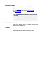
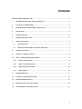
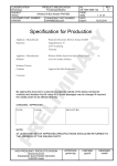
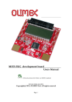
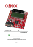
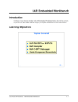
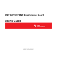
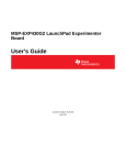
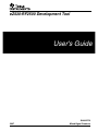
eZ430-RF2500 Development Tool s e r ' s G u i d e User's Guide 2007 SLAU227A Mixed Signal Products If You Need Assistance Support for the MSP430 device and the eZ430-RF2500 is provided by the Texas Instruments Product Information Center (PIC). Contact information for the PIC can be found on the TI web site at www.ti.com. Additional device-specific information can be found on the MSP430 web site at www.ti.com/msp430 and www.ti.com/ez430-rf. Note: IAR Embedded Workbench® KickStart is supported by Texas Instruments. Although IAR Embedded Workbench KickStart is a product of IAR, Texas Instruments provides support for KickStart. Therefore, please do not request support for KickStart from IAR. Please consult all provided documentation with KickStart before requesting assistance. We Would Like to Hear from You If you have any comments, feedbacks, or suggestions, please let us know by contacting us at [email protected]. Trademarks SimpliciTI is a trademark of Texas Instruments. All other trademarks are the property of their respective owners. Contents eZ430-RF2500 Development Tool...............................................................................................1 1. eZ430-RF2500 Overview. Wireless Made Easy. ...............................................................2 2. Kit Contents, eZ430-RF2500.............................................................................................3 3. Developing With eZ430-RF2500T Target Board ...............................................................4 4. Specifications ...................................................................................................................5 5. Supported Devices............................................................................................................6 6. MSP430 Application UART ...............................................................................................6 7. Software Installation..........................................................................................................7 7.1. Installing the IDE ...........................................................................................................7 7.2. Installing the Sensor Monitor Visualizer Application .......................................................7 8. Hardware Installation ........................................................................................................7 9. SimpliciTI™ Network Protocol...........................................................................................8 10. Demo – eZ430-RF2500 Sensor Monitor............................................................................8 10.1. Demo Hardware Setup...............................................................................................9 10.2. Demo Firmware Download .........................................................................................9 10.3. Demo Software GUI Setup.......................................................................................10 10.4. Demo Options..........................................................................................................10 11. Suggested Reading.........................................................................................................11 12. Frequently Asked Questions (FAQ).................................................................................12 13. eZ430-RF2500 Schematics.............................................................................................14 14. Detailed Hardware Installation Guide ..............................................................................18 15. IAR Workbench Compatibility Guide...............................................................................21 1 1. eZ430-RF2500 Overview. Wireless Made Easy. The eZ430-RF2500 is a complete USB-based MSP430 wireless development tool providing all the hardware and software to evaluate the MSP430F2274 microcontroller and CC2500 2.4-GHz wireless transceiver. The eZ430-RF2500 uses the IAR Embedded Workbench Integrated Development Environment (IDE) or Code Composer Essentials (CCE) to write, download, and debug an application. The debugger is unobtrusive, allowing the user to run an application at full speed with both hardware breakpoints and single stepping available while consuming no extra hardware resources. The eZ430-RF2500T target board is an out-of-the box wireless system that may be used with the USB debugging interface, as a stand-alone system with or without external sensors, or may be incorporated into an existing design. The new USB debugging interface enables the eZ430-RF2500 to remotely send and receive data from a PC using the MSP430 Application UART. eZ430-RF2500 features: • USB debugging and programming interface featuring a driverless installation and application backchannel • 21 available development pins • Highly integrated, ultra-low-power MSP430 MCU with 16-MHz performance • Two general-purpose digital I/O pins connected to green and red LEDs for visual feedback • Interruptible push button for user feedback Spy Bi-Wire & Pushbutton 2x LEDs CC2500 MSP430 Appliation UART Chip Antenna USB Powered MSP430F2274 18 Accessible Pins Figure 1. eZ430-RF2500 2 Figure 2. eZ430-RF2500 Battery Board 2. Kit Contents, eZ430-RF2500 • • The hardware includes: • Two eZ430-RF2500T target boards • One eZ430-RF USB debugging interface • One AAA battery pack with expansion board (batteries included) One MSP430 Development Tool CD-ROM containing documentation and new development software for eZ430-RF2500: • MSP430x2xx Family User’s Guide, SLAU144 • eZ430-RF2500 User’s Guide, SLAU227 • Code Composer Essentials (CCE), SLAC063 • IAR Embedded Workbench (KickStart Version), SLAC050 • eZ430-RF2500 Sensor Monitor (Code and Visualizer), SLAC139 NOTE: Please visit Texas Instrument’s website for latest versions www.ti.com/msp430 3 3. Developing With eZ430-RF2500T Target Board The eZ430-RF2500 can be used as a stand-alone development tool. Additionally, the eZ430-RF2500T target board may also be detached from the debugging interface and integrated into another design by removing the plastic enclosure. The target board features an MSP430F2274 and most of its pins are easily accessible. The pins are shown in Figure 3 and the following tables: Figure 3. eZ430-RF2500 Development Tool eZ430-RF2500T Target Board Pinouts Pin 1 2 Function GND VCC Description Ground reference Supply voltage 3 P2.0 / ACLK / A0 / OA0I0 General-purpose digital I/O pin / ACLK output / ADC10, analog input A0 4 P2.1 / TAINCLK / SMCLK / A1 / OA0O 5 6 7 8 9 10 11 12 13 14 15 16 17 18 *Pins General-purpose digital I/O pin / ADC10, analog input A1 Timer_A, clock signal at INCLK, SMCLK signal output General-purpose digital I/O pin / ADC10, analog input A2 P2.2 / TA 0 / A2 / OA0I1 Timer_A, capture: CCI0B input/BSL receive, compare: OUT0 output General-purpose digital I/O pin / Timer_A, capture: CCI1B input, compare: P2.3 / TA 1 / A3 / VREF − / OUT1 output / ADC10, analog input A3 / negative reference voltage VeREF − / OA1I1 / OA1O output/input P2.4 / TA 2 / A4 / VREF + / General-purpose digital I/O pin / Timer_A, compare: OUT2 output / VeREF + / OA1I0 ADC10, analog input A4 / positive reference voltage output/input General-purpose digital I/O pin / ADC10 analog input A12 / P4.3 / TB0 / A12 / OA0O Timer_B, capture: CCI0B input, compare: OUT0 output General-purpose digital I/O pin / ADC10 analog input A13 / P4.4 / TB1 / A13 / OA1O Timer_B, capture: CCI1B input, compare: OUT1 output General-purpose digital I/O pin / ADC10 analog input A14 / P4.5 / TB2 / A14 / OA0I3 Timer_B, compare: OUT2 output General-purpose digital I/O pin / ADC10 analog input A15 / P4.6 / TBOUTH / A15 / OA1I3 Timer_B, switch all TB0 to TB3 outputs to high impedance GND Ground reference P2.6 / XIN (GDO0) General-purpose digital I/O pin / Input terminal of crystal oscillator P2.7 / XOUT (GDO2) General-purpose digital I/O pin / Output terminal of crystal oscillator General-purpose digital I/O pin P3.2 / UCB 0SOMI / UCB 0SCL USCI_B0 slave out/master in in SPI mode, SCL I2C clock in I2C mode General-purpose digital I/O pin P3.3 / UCB 0CLK / UCA 0STE USCI_B0 clock input/output / USCI_A0 slave transmit enable P3.0 / UCB 0STE / UCA 0CLK / General-purpose digital I/O pin / USCI_B0 slave transmit enable / USCI_A0 A5 clock input/output / ADC10, analog input A5 General-purpose digital I/O pin / USCI_B0 slave in/master out in SPI mode, P3.1 / UCB 0SIMO / UCB 0SDA SDA I2C data in I2C mode 13 to 18 may be used to test the connection between the MSP430F2274 and CC2500. Battery Board Pinouts Pin Function 1 P3.4 / UCA 0TXD / UCA 0SIMO 2 GND 3 #RST/SBWTDIO 4 TEST/SBWTCK 5 VCC (3.6V) 6 P3.5 / UCA 0RXD / UCA 0SOMI Description General-purpose digital I/O pin / USCI_A0 transmit data output in UART mode (UART communication from 2274 to PC), slave in/master out in SPI mode Ground Reference Reset or nonmaskable interrupt input. Spy-Bi-Wire test data input/output during programming and test Selects test mode for JTAG pins on Port1. The device protection fuse is connected to TEST. Spy-Bi-Wire test clock input during programming and test Supply Voltage General-purpose digital I/O pin / USCI_A0 receive data input in UART mode (UART communication from 2274 to PC), slave out/master in in SPI mode 4 4. Specifications MSP430F2274 • 16-MIPS performance • 200-ksps 10-bit SAR ADC • Two built-in operational amplifiers • Watchdog timer, 16-bit Timer_A3 and Timer_B3 • USCI module supporting UART/LIN, (2) SPI, I2C, or IrDA • Five low-power modes drawing as little as 700 nA in standby • PARAMETER MIN TYP MAX UNIT OPERATING CONDITIONS Operating supply voltage 1.8 3.6 V Operating free-air temperature range -40 85 ˚C CURRENT CONSUMPTION Active mode at 1 MHz, 2.2 V 270 390 µA Standby mode 0.7 1.4 µA Off mode with RAM retention 0.1 0.5 µA 16 MHz OPERATING FREQUENCY VCC ≥ 3.3 V CC2500 • 2.4-GHz radio-frequency (RF) transceiver • Programmable data rate up to 500 kbps • Low current consumption • PARAMETER MIN TYP MAX UNIT 3.6 V CONDITION OPERATING CONDITIONS Operating supply voltage 1.8 CURRENT CONSUMPTION RX input signal at the sensitivity limit, 250 kbps RX input signal 30 dB above the sensitivity limit, 250 kbps 16.6 mA Optimized current 18.8 mA Optimized sensitivity 13.3 mA Optimized current Optimized sensitivity 15.7 mA Current consumption TX (0 dBm) 21.2 mA Current consumption TX (-12 dBm) 11.1 mA RF CHARACTERISTICS Frequency range 2400 2483.5 MHz Data rate (programmable) 1.2 500 kbps Output power (programmable) -30 0 dBm Sensitivity, 10 kbps Sensitivity, 250 kbps -99 dBm Optimized current, 2-FSK, 230-kHz RX filter bandwidth, 1% PER -101 dBm Optimized sensitivity -87 dBm Optimized current, 500-kHz RX filter bandwidth, 1% PER -89 dBm Optimized sensitivity 5 5. Supported Devices The eZ430-RF USB debugging interface may be used as a standard Flash Emulation Tool through its Spy-Bi-Wire interface. The eZ430-RF USB debugging interface supports the following MSP430 families: • MSP430F20xx • MSP430F22xx The connector on the USB debugging interface is backward compatible with the eZ430-F2013 and T2012 target boards. RX 3.6V TEST/SBWTCK #RST/SBWTDIO Supports eZ430-F2013 and T2012 target boards. GND TX Figure 4. eZ430-RF2500 USB Debugging Interface 6-Pin Male Header 6. MSP430 Application UART The eZ430-RF USB debugging interface features a back channel MSP430 Application UART that may be used independently of a debug session. This allows the user to transfer serial data to a terminal window at a fixed rate of 9600 bps with no flow control. See Figure 5 for typical settings. Figure 5. 9600 bps With No Flow Control Check the Device Manager for COM port assignment of the MSP430 Application UART. For more details, see Section 14: Detailed Hardware Installation Guide. 6 7. Software Installation The CD-ROM includes two different development software tools for the MSP430—IAR Embedded Workbench KickStart and Code Composer Essentials (CCE). The term “KickStart” refers to the limited version of Embedded Workbench that allows up to 4 KB of C-code compilation. The included CCE is also limited, but it allows up to 8 KB of code compilation. The full version of CCE Pro offers unlimited code compilation and can be purchased from www.ti.com/msp430. 7.1. Installing the IDE 1. Insert the eZ430-RF2500 CD-ROM into the computer. The eZ430-RF2500 start page should automatically display. If it does not display, use a browser to open “index.htm”, which is located in the root directory of the eZ430-RF2500 CD-ROM. The eZ430-RF2500 is compatible with Windows® 2000 and Windows XP. 2. Select Software Æ IAR Workbench KickStart / Code Composer Essentials and follow the instructions. 3. Respond to the prompts to install the software. The installation procedure installs the IDE and TI files. Finish the installation. 7.2. Installing the Sensor Monitor Visualizer Application 1. Select Software Æ Sensor Monitor Visualizer and follow the instructions. 2. Choose the installation path for the software. 3. Open the eZ430-RF2500 Sensor Monitor using the shortcut installed on the desktop. 8. Hardware Installation 1. Insert the eZ430-RF into USB port. The debugging interface automatically installs itself. 2. When prompted for the software for the MSP430 Application UART, allow Windows to Install the software automatically. This is only possible if either IAR KickStart R4.64 (or higher) or the Sensor Monitor Visualizer has already been installed. For more information, see Section 14: Detailed Hardware Installation Guide. 7 9. SimpliciTI™ Network Protocol The SimpliciTI network protocol is a proprietary, low-power radiofrequency (RF) protocol targeting simple, small RF networks (<100 nodes). The SimpliciTI network protocol is designed for easy implementation with minimal microcontroller resource requirements. The protocol runs out of the box on TI’s MSP430 ultra-low-power microcontrollers and multiple RF transceivers. Small low-power RF networks typically contain battery-operated devices, which require long battery life, low data rate and low duty cycle, and have a limited number of nodes talking directly to each other. With the SimpliciTI network protocol, MCU resource requirements are minimal, resulting in lower system cost for low-power RF networks. More complex mesh networks that need routing typically require 10× the program memory and RAM to implement. Despite the modest resources required, SimpliciTI network protocol supports End Devices (EDs) in a peer-to-peer network topology, the option to use an Access Point (AP) to store and forward messages, and Range Extenders (REs) to extend the range of the network up to four hops. Future releases will add more sophisticated features such as frequency agility, an ETSI-compliant listen-before-talk discipline, and a software security routine for message encryption. The SimpliciTI network protocol supports a wide range of low-power applications including alarm and security (smoke detectors, glass breakage detectors, carbon monoxide sensors, and light sensors), automated meter reading (gas meters and water meters), home automation (appliances, garage door openers, and environmental devices), and active RFID. The SimpliciTI network protocol is provided as source code under a free license without royalties. Developers are encouraged to adapt the protocol to their own specific application needs. For information on compatibility, updates, and the latest version of the SimpliciTI protocol, visit www.ti.com/simpliciti. The eZ430-RF2500 demo application uses the SimpliciTI protocol to demonstrate a temperature sensor network application that provides a starting point to develop a wireless applications. 10. Demo – eZ430-RF2500 Sensor Monitor eZ430-RF2500 is preloaded with a wireless temperature sensor network firmware and may be reprogrammed at any time. This network consists of an Access Point that measures its own temperature and also wirelessly receives temperature measurements from End Devices. End Devices measure their temperature once per second and then enter a low-power mode to reduce battery usage. The Access Point transmits all measured data to the PC through the UART backchannel. The included PC Sensor Monitor Visualizer provides a demonstration of the eZ430-RF2500 using the SimpliciTI protocol across a star network. In the PC Sensor Monitor Visualizer, the center node is the Access Point and the attached bubbles are the End Devices. The PC application 8 displays the temperature of both the End Devices and Access Point. Additionally, the PC application is capable of simulating distance from its access point when the End Devices are moved. The number of End Devices can be expanded by adding more target boards in the star network as seen in Figure 6. Figure 6. eZ430-RF2500 Sensor Monitor 10.1. Demo Hardware Setup 1. Connect the eZ430-RF2500 to a USB port on the PC. 2. Connect the second eZ430-RF2500T target board to the battery board. Insert the jumper on the board to power up the device. 10.2. Demo Firmware Download The following steps describe how to update the demo application firmware on the eZ430-RF2500 target boards and are not required out of the box. 1. Open IAR Workbench KickStart. 2. Select Open Existing Workspace and browse for the demo application workspace (*.eww) file. The project is available on the CD or at http://www.ti.com/lit/zip/slac139. 3. To download demo firmware, follow steps 3a for Access Point firmware and 3b for End Device firmware. 3a. Right click on Access Point project in the workspace and click Set as Active as shown in Figure 7. 3b. Right click on End Device project in the workspace and click Set as Active. 9 Figure 7. IAR Embedded Workbench KickStart Workspace 4. Select Project Æ Debug in IAR to download the code for the target boards. 5. Select Debug Æ Go to start running code while in debug mode. 6. Select Debug Æ Stop Debugging exits the debug mode while leaving the target board executing code. 10.3. Demo Software GUI Setup 1. Ensure the Access Point is connected to the PC. 2. Apply power to the End Device. 3. Launch eZ430-RF2500 Sensor Monitor Demo Visualizer. After installation, a shortcut is placed on the desktop. It is available on the CD and online at http://www.ti.com/lit/zip/slac139. 4. The application should automatically display End Devices when in range. 10.4. Demo Options 1. Go to Menu Æ Settings. 2. Under the settings menu, the demo application is capable of displaying values in Celsius or Fahrenheit. 3. Checking the box Disable Animations disables the dynamic distance change, thus decreasing CPU processing on PC. 4. See the demo application help file by clicking Help for more detailed options. 10 11. Suggested Reading The primary sources of MSP430 information are the device-specific data sheets and user’s guides. The most up-to-date versions of the user’s guide documents available at the time of production have been provided on the CD-ROM included with this tool. The most current information is found at www.ti.com/msp430. Information specific to the eZ430-RF2500 development tool can be found at www.ti.com/ez430-rf. MSP430 device user’s guides and the FET user's guide may be accessed from the main page on the CD-ROM under the User’s Guides section. The FET user's guide includes detailed information on setting up a project for the MSP430 using IAR. Documents describing the IAR tools (Workbench/C-SPY, the assembler, the C compiler, the linker, and the library) are located in common\doc and 430\doc. The documents are in PDF format. Supplements to the documents (i.e., the latest information) are available in HTML format within the same directories. 430\doc\readme_start.htm provides a convenient starting point for navigating the IAR documentation. 11 12. Frequently Asked Questions (FAQ) 1) Does the eZ430-RF2500 support fuse blow? The eZ430-RF USB debugging interface lacks the JTAG security fuse-blow capability. To ensure firmware security on devices going to production, the USB Flash Emulation Tool or the Gang Programmer, which include the fuse-blow feature, are recommended. 2) What is the voltage supplied to the eZ430-RF2500T target board from the debugging interface? The eZ430-RF USB debugging interface supplies a regulated 3.6 V to the eZ430-RF2500T target board. 3) Can other programming tools interface to the eZ430-RF2500T target board? The eZ430-RF2500T target board works with any programming tool supporting the 2-wire Spy-Bi-Wire interface. Both the MSP430 USB FET (MSP-FET430UIF) and the Gang Programmer (MSPGANG430) support these devices. See MSP-FET430 Flash Emulation Tool User’s Guide (SLAU138) for details on using MSP430 USB FET and the Gang Programmer for a 2-wire Spy-BiWire interface. 4) What versions of IAR Embedded Workbench and Code Composer Essentials are supported? The eZ430-RF2500 hardware is supported by IAR Embedded Workbench KickStart Release 4.64 (IAR 3.42F) and Code Composer Essentials v2.03 (SP3) or higher. At the time of print, CCE is currently not supported by the SimpliciTI protocol or the Sensor Monitor Demo. Please check the TI web site for updates. 5) What are the part numbers for the connectors between the eZ430-RF USB debugger and the eZ430-RF2500T target board? • Header: Mill-Max 850-10-006-20-001000 • Socket: Mill-Max 851-93-006-20-001000 Mill-Max: http://www.mill-max.com 6) Where can I obtain more information about the 2.4-GHz chip antenna? Part Number: 7488910245 Wϋrth Electronik Group: www.we-online.com 12 7) I am not able to select the MSP430 Application UART, cannot receive data, or the demo app doesn’t appear to change. Ensure that the Application UART driver is correctly installed. This is done by either running the installer for the Sensor Monitor Visualizer or IAR KickStart 3.42F or higher and following the directions in Section 14. To determine if the driver is correctly installed: 1. Plug in the eZ430-RF USB debugging interface 2. Right click My Computer and select Properties. 3. Select the Hardware tab and click on Device Manager. 4. Under Ports (COM & LPT) should be an entry for “MSP430 Application UART (COM xx)”. If the entry is there, but no characters are received, restart the PC. If the Application UART is not listed, please install the driver by following the instructions in Section 14: Detailed Hardware Installation Guide. 8) When trying to compiler the Sensor Monitor Demo project in IAR, I receive the following error: Error[e117]: Incompatible runtime models. Module ISR specifies that '__rt_version' must be '3', but module LHAL_GDOxHandlers has the value '2' Please use the latest version of the demo source code off the web (http://www.ti.com/lit/zip/slac139) and use IAR KickStart 4.x. Early versions of the demo code included a precompiled version of the SimpliciTI library for IAR 3.x. IAR 4.x changes the calling conventions, which returns Error[e117] when trying to build libraries for an older version of the compiler. 13 13. eZ430-RF2500 Schematics Figure 8. eZ430-RF, USB Debugging Interface, Schematic 14 Figure 9. eZ430-RF, USB Debugging Interface, Schematic 15 Figure 10. eZ430-RF2500T, Target Board and Battery Board, Schematic 16 Figure 11. eZ430-RF, USB Debugger, PCB Components Layout Top Layer Bottom Layer Figure 12. eZ430-RF, USB Debugger, PCB Layout Figure 13. eZ430-RF2500T, Target Board, PCB Layout 17 14. Detailed Hardware Installation Guide 1. Insert the eZ430-RF2500 CD-ROM into a CD drive. 2. Install IAR Embedded Workbench KickStart (R4.64 or newer) included on the CD or from www.ti.com/msp430. 3. Insert the eZ430-RF2500 into a USB port of the PC. 4. Windows should recognize the new hardware as Texas Instruments MSP-FET430UIF (see Figure 14). Windows should automatically install the drivers for the MSP-FET430UIF as a HID tool. Figure 14. Windows XP Hardware Recognition 5. Windows will recognize another new hardware driver to be installed called MSP430 Application UART (see Figure 15). Figure 15. Windows XP Hardware Recognition for MSP430 Application UART NOTE: This Installation Step is Optional. The USB debugging interface will work without the MSP430 Application UART. 18 6. The Found New Hardware Wizard opens a dialog window. Select No, not this time and click Next (see Figure 16). Figure 16. Windows XP Found New Hardware Wizard 7. Select Install the software automatically (Recommended) (see Figure 17), if IAR KickStart R4.64 or higher has already been installed. Figure 17. Windows XP Hardware Wizard 19 8. The Wizard should find the appropriate driver for a Windows XP system; it shows a warning that Microsoft did not certify the driver. The drivers have been tested exhaustively, and this warning may be ignored. Click Continue Anyway (see Figure 18). Figure 18. Windows XP Warning 9. The Wizard continues to install the driver and then provides notification when it has finished the installation of the software. 20 10. The eZ430-RF2500 is now installed and ready to use. The assigned COM port for the MSP430 Application UART is shown in the Windows Device Manager (see Figure 19). Figure 19. Device Manager 15. IAR Workbench Compatibility Guide Note: In this document, “IAR version” refers to the IAR compiler version. This can be obtained by clicking Help Æ About Æ Product Info. IAR KickStart version 3.42F (FET_R4.64) Minimum version compatible with eZ430-RF USB debugging interface board Compatible with eZ430-RF2500 Sensor Monitor demo v1.00 IAR KickStart version 4.09A+ (FET_R5.10+) Compatible with eZ430-RF USB debugging interface board Compatible with SimpliciTI libraries 1.0.3+ Compatible with eZ430-RF2500 Sensor Monitor demo v1.02+ 21 EVALUATION BOARD/KIT IMPORTANT NOTICE Texas Instruments (TI) provides the enclosed product(s) under the following conditions: This evaluation board/kit is intended for use for ENGINEERING DEVELOPMENT, DEMONSTRATION, OR EVALUATION PURPOSES ONLY and is not considered by TI to be a finished end-product fit for general consumer use. Persons handling the product(s) must have electronics training and observe good engineering practice standards. As such, the goods being provided are not intended to be complete in terms of required design-, marketing-, and/or manufacturing-related protective considerations, including product safety and environmental measures typically found in end products that incorporate such semiconductor components or circuit boards. This evaluation board/kit does not fall within the scope of the European Union directives regarding electromagnetic compatibility, restricted substances (RoHS), recycling (WEEE), FCC, CE or UL, and therefore may not meet the technical requirements of these directives or other related directives. Should this evaluation board/kit not meet the specifications indicated in the User’s Guide, the board/kit may be returned within 30 days from the date of delivery for a full refund. THE FOREGOING WARRANTY IS THE EXCLUSIVE WARRANTY MADE BY SELLER TO BUYER AND IS IN LIEU OF ALL OTHER WARRANTIES, EXPRESSED, IMPLIED, OR STATUTORY, INCLUDING ANY WARRANTY OF MERCHANTABILITY OR FITNESS FOR ANY PARTICULAR PURPOSE. The user assumes all responsibility and liability for proper and safe handling of the goods. Further, the user indemnifies TI from all claims arising from the handling or use of the goods. Due to the open construction of the product, it is the user’s responsibility to take any and all appropriate precautions with regard to electrostatic discharge. EXCEPT TO THE EXTENT OF THE INDEMNITY SET FORTH ABOVE, NEITHER PARTY SHALL BE LIABLE TO THE OTHER FOR ANY INDIRECT, SPECIAL, INCIDENTAL, OR CONSEQUENTIAL DAMAGES. TI currently deals with a variety of customers for products, and therefore our arrangement with the user is not exclusive. TI assumes no liability for applications assistance, customer product design, software performance, or infringement of patents or services described herein. Please read the User’s Guide and, specifically, the Warnings and Restrictions notice in the User’s Guide prior to handling the product. This notice contains important safety information about temperatures and voltages. For additional information on TI’s environmental and/or safety programs, please contact the TI application engineer or visit www.ti.com/esh. No license is granted under any patent right or other intellectual property right of TI covering or relating to any machine, process, or combination in which such TI products or services might be or are used. FCC WARNING This evaluation board/kit is intended for use for ENGINEERING DEVELOPMENT, DEMONSTRATION, OR EVALUATION PURPOSES ONLY and is not considered by TI to be a finished end-product fit for general consumer use. It generates, uses, and can radiate radio frequency energy and has not been tested for compliance with the limits of computing devices pursuant to part 15 of FCC rules, which are designed to provide reasonable protection against radio frequency interference. Operation of this equipment in other environments may cause interference with radio communications, in which case the user at his own expense will be required to take whatever measures may be required to correct this interference. EVM WARNINGS AND RESTRICTIONS It is important to operate this EVM within the input voltage range of 1.8 V to 3.6 V and the output voltage range of 1.8 V to 3.6 V. Exceeding the specified input range may cause unexpected operation and/or irreversible damage to the EVM. If there are questions concerning the input range, please contact a TI field representative prior to connecting the input power. Applying loads outside of the specified output range may result in unintended operation and/or possible permanent damage to the EVM. Please consult the EVM User's Guide prior to connecting any load to the EVM output. If there is uncertainty as to the load specification, please contact a TI field representative. During normal operation, some circuit components may have case temperatures greater than 60 C. The EVM is designed to operate properly with certain components above 60 C as long as the input and output ranges are maintained. These components include but are not limited to linear regulators, switching transistors, pass transistors, and current sense resistors. These types of devices can be identified using the EVM schematic located in the EVM User's Guide. When placing measurement probes near these devices during operation, please be aware that these devices may be very warm to the touch. Mailing Address: Texas Instruments, Post Office Box 655303, Dallas, Texas 75265 Copyright © 2007, Texas Instruments Incorporated 22 IMPORTANT NOTICE Texas Instruments Incorporated and its subsidiaries (TI) reserve the right to make corrections, modifications, enhancements, improvements, and other changes to its products and services at any time and to discontinue any product or service without notice. Customers should obtain the latest relevant information before placing orders and should verify that such information is current and complete. All products are sold subject to TI’s terms and conditions of sale supplied at the time of order acknowledgment. TI warrants performance of its hardware products to the specifications applicable at the time of sale in accordance with TI’s standard warranty. Testing and other quality control techniques are used to the extent TI deems necessary to support this warranty. Except where mandated by government requirements, testing of all parameters of each product is not necessarily performed. TI assumes no liability for applications assistance or customer product design. Customers are responsible for their products and applications using TI components. To minimize the risks associated with customer products and applications, customers should provide adequate design and operating safeguards. TI does not warrant or represent that any license, either express or implied, is granted under any TI patent right, copyright, mask work right, or other TI intellectual property right relating to any combination, machine, or process in which TI products or services are used. Information published by TI regarding third-party products or services does not constitute a license from TI to use such products or services or a warranty or endorsement thereof. Use of such information may require a license from a third party under the patents or other intellectual property of the third party, or a license from TI under the patents or other intellectual property of TI. Reproduction of TI information in TI data books or data sheets is permissible only if reproduction is without alteration and is accompanied by all associated warranties, conditions, limitations, and notices. Reproduction of this information with alteration is an unfair and deceptive business practice. TI is not responsible or liable for such altered documentation. Information of third parties may be subject to additional restrictions. Resale of TI products or services with statements different from or beyond the parameters stated by TI for that product or service voids all express and any implied warranties for the associated TI product or service and is an unfair and deceptive business practice. TI is not responsible or liable for any such statements. TI products are not authorized for use in safety-critical applications (such as life support) where a failure of the TI product would reasonably be expected to cause severe personal injury or death, unless officers of the parties have executed an agreement specifically governing such use. Buyers represent that they have all necessary expertise in the safety and regulatory ramifications of their applications, and acknowledge and agree that they are solely responsible for all legal, regulatory and safety-related requirements concerning their products and any use of TI products in such safety-critical applications, notwithstanding any applications-related information or support that may be provided by TI. Further, Buyers must fully indemnify TI and its representatives against any damages arising out of the use of TI products in such safety-critical applications. TI products are neither designed nor intended for use in military/aerospace applications or environments unless the TI products are specifically designated by TI as military-grade or "enhanced plastic." Only products designated by TI as military-grade meet military specifications. Buyers acknowledge and agree that any such use of TI products which TI has not designated as military-grade is solely at the Buyer's risk, and that they are solely responsible for compliance with all legal and regulatory requirements in connection with such use. TI products are neither designed nor intended for use in automotive applications or environments unless the specific TI products are designated by TI as compliant with ISO/TS 16949 requirements. Buyers acknowledge and agree that, if they use any non-designated products in automotive applications, TI will not be responsible for any failure to meet such requirements. Following are URLs where you can obtain information on other Texas Instruments products and application solutions: Products Amplifiers Data Converters DSP Clocks and Timers Interface Logic Power Mgmt Microcontrollers RFID RF/IF and ZigBee® Solutions amplifier.ti.com dataconverter.ti.com dsp.ti.com www.ti.com/clocks interface.ti.com logic.ti.com power.ti.com microcontroller.ti.com www.ti-rfid.com www.ti.com/lprf Applications Audio Automotive Broadband Digital Control Medical Military Optical Networking Security Telephony Video & Imaging Wireless www.ti.com/audio www.ti.com/automotive www.ti.com/broadband www.ti.com/digitalcontrol www.ti.com/medical www.ti.com/military www.ti.com/opticalnetwork www.ti.com/security www.ti.com/telephony www.ti.com/video www.ti.com/wireless Mailing Address: Texas Instruments, Post Office Box 655303, Dallas, Texas 75265 Copyright 2008, Texas Instruments Incorporated