1
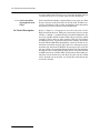
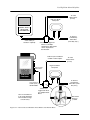
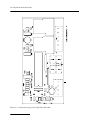
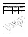
High-Low Alarm Relay
Box
Instruction Manual
Part #60-3403-071
Copyright © 1991, 2002. All rights reserved, Isco, Inc.
Revision C, August, 2002
Foreword
This instruction manual is designed to help you gain a thorough understanding of the
operation of the equipment. Isco recommends that you read this manual completely
before placing the equipment in service.
Although Isco designs reliability into all equipment, there is always the possibility of a
malfunction. This manual may help in diagnosing and repairing the malfunction.
If the problem persists, call or email the Isco Customer Service Department for assistance. Contact information is provided below. Simple difficulties can often be diagnosed over the phone. If it is necessary to return the equipment to the factory for
service, please follow the shipping instructions provided by the Customer Service
Department, including the use of the Return Authorization Number specified. Be
sure to include a note describing the malfunction. This will aid in the prompt
repair and return of the equipment.
Isco welcomes suggestions that would improve the information presented in this manual or enhance the operation of the equipment itself.
Contact Information
Phone:
(800) 228-4373
(USA, Canada, Mexico)
(402) 464-0231
(Outside North America)
Repair Service: (800) 775-2965
(Analytical and Process
Monitoring Instruments)
(800) 228-4373
Fax:
(Samplers and Flow Meters)
(402) 465-3022
Email address: [email protected]
Website:
www.isco.com
Return equipment to: 4700 Superior Street, Lincoln, NE 68504-1398
Other correspondence: P.O. Box 82531, Lincoln, NE 68501-2531
Isco High-Low Alarm Relay Box
Table of Contents
1.1
1.2
1.3
1.4
1.5
Introduction . . . . . . . . . . . . . . . . . . . . . . . . . . . . . . . . . . . . . . . . . . . . . . . . . . . . . . . .
Setting the Limit Switches . . . . . . . . . . . . . . . . . . . . . . . . . . . . . . . . . . . . . . . . . . . .
Installation . . . . . . . . . . . . . . . . . . . . . . . . . . . . . . . . . . . . . . . . . . . . . . . . . . . . . . . .
Wiring to Model 3010 and 3020 Flow Transmitters . . . . . . . . . . . . . . . . . . . . . . . .
Wiring to 4200 Series Flow Meters . . . . . . . . . . . . . . . . . . . . . . . . . . . . . . . . . . . . .
1.5.1 Distances Greater Than 25 Feet . . . . . . . . . . . . . . . . . . . . . . . . . . . . . . . . . .
1.5.2 Connection With a Tipping Bucket Rain Gauge . . . . . . . . . . . . . . . . . . . . .
1.6 Circuit Description . . . . . . . . . . . . . . . . . . . . . . . . . . . . . . . . . . . . . . . . . . . . . . . . . .
1.7 Replacement Parts List. . . . . . . . . . . . . . . . . . . . . . . . . . . . . . . . . . . . . . . . . . . . . . .
1-1
1-2
1-2
1-2
1-3
1-3
1-4
1-4
1-7
i
Isco High-Low Alarm Relay Box
Table of Contents
ii
Isco High-Low Alarm Relay Box
Section 1
1.1 Introduction
The Isco High-Low Alarm Relay Box monitors flow rate data
from 3000 Series Flow Transmitters and 4200 Series Flow
Meters. Alarm relays trip when the flow rate falls below or
exceeds programmed limits. High and low set points are
user-selected and range from 0% to 99% in 1% increments. Output from the High-Low Alarm Relay Box is the switching of form
C (SPDT) relay contacts. Two relays are provided; one for a high
alarm and the other for a low alarm. The availability of form C
contacts (both NO [normally open] and NC [normally closed] contacts) means that loads may be turned on or off. Relay contacts
are rated at 3 Amperes, 24 volts AC or DC. The Alarm Box operates on 12 VDC supplied by the transmitter or flow meter. Current consumption in standby condition is approximately 10 mA.
In alarm condition, the current increases to 190 mA. Up to four
Alarm Boxes can be used with a single transmitter or flow meter.
CAUTION
Use the Alarm Box with care in battery-powered flow meter
installations. The Alarm Box draws its operating power from
the flow meter, causing a significant reduction in battery life.
Each Alarm Box will consume about one ampere-hour of battery capacity in four days, reducing capacity approximately
25%. In Alarm condition, one Alarm Box will discharge a fresh
(4 Ah) battery in about 21 hours.
Figure 1-1 High-Low Alarm Box (Cover Removed)
1-1
Isco High-Low Alarm Relay Box
1.2 Setting the Limit
Switches
The High-Low Alarm Relay Box contains a microprocessor that
interprets serial data from the transmitter or flow meter and
compares it with values entered by the user as trip-points for the
relays. Rotary switches inside the Alarm Box set the high and
low trip points. There are two rotary switches for each limit. The
switches labeled MSD (most significant digit) determine the first
digit of the percentage entered as a set point. For example, if you
want to enter a low level alarm of 18%, you would set the LOW
LIMIT MSD switch to 1, and the LOW LIMIT LSD switch to 8.
Use the same method to program the HIGH LIMIT switch. For
example, if you want to set the high limit to 79%, you would set
the HIGH LIMIT MSD switch to 7 and the HIGH LIMIT LSD
switch to 9.
1.3 Installation
A stainless steel mounting plate is attached to the back of the
plastic case with two slotted holes punched into the plate. The
slots will accommodate up to 3/16” hardware. Drill two mounting
holes on 3” centers. Two threaded holes in the box allow the use
of either 1/2” conduit fittings or Stahlin fittings (watertight compression bushings). While suitable for use in damp locations, the
High-Low Alarm Relay Box should not be installed submersion is
a possibility. Where subfreezing temperatures are expected, Isco
recommends installation of the Alarm Box indoors or in a heated
location, as the microprocessor is not specified to operate below
32° F (0° C).
1.4 Wiring to Model 3010
and 3020 Flow
Transmitters
Connecting the Alarm Box to a flow transmitter requires three
wires. A three wire cable typically has the following wires in it:
black, white, and another color, such as red or green. Connect the
wires as follows:
Table 1-1 3000 Series Wiring Instructions
Terminals in 3000
Series Flow
Transmitter
Terminal
Strip#
Wire
Colors
Terminals in Alarm
Box
2312 INTERFACE +
TS2
BLACK
+12VDC
2312 INTERFACE -
TS2
WHITE
-12VDC
(OTHER)
DATA
2312 INTERFACE OUT TS2
Wire additional Alarm Boxes together in parallel as described
in the table above. Use no more than four Alarm Boxes per flow
transmitter. See Figure 1-2. The maximum recommended distance between the Flow Meter and the High-Low Alarm Box is
250 feet (76 m). The minimum wire gauge is #18 AWG. In electrically noisy environments, shielded cable is recommended. The
wire colors shown are for example only; use any color of wire and
cable available, but make sure the connections end up the same
as shown.
1-2
Isco High-Low Alarm Relay Box
To connect external devices to the high level or low level,
alarm relay:
Use NO and COMM for devices to turn ON when the alarm trips.
Use NC and COMM for devices to turn OFF when the alarm
trips.
Wire gauge and the length of the cable run depend on the device
being controlled. Recommended limits for wiring to the relay
contacts only are 1000 feet maximum cable run and #18 AWG
wire size.
WARNING
To prevent hazard of electric shock, use the relay contacts
for low voltage pilot duty only. Do not wire 120 VAC or
higher voltages directly to the relay contacts.
1.5 Wiring to 4200 Series
Flow Meters
Connecting the High-Low Alarm Box to a 4200 Series Flow
Meter requires a connect cable with an M/S connector (available
from Isco) that attaches to the Rain Gauge connector on the side
of the flow meter case. See Figure 1-2.
On one end of the cable there is a 4-pin male M/S connector
which attaches to the Rain Gauge connector on the flow meter.
The other end of the cable terminates in three stripped wires
that attach as follows to the terminal block on the left side of the
High-Low Alarm Relay Box:
Rain Gauge
BLACK +12VDC
GREEN -12VDC
Rain Gauge Connector Icon
WHITE DATA
Up to four Alarm Boxes may be wired together in parallel as
described in the table above. Due to increased current draw, Isco
recommends use of no more than one Alarm Box with any battery-powered flow meter.
1.5.1 Distances Greater
Than 25 Feet
If the Alarm Box and 4200 Series Flow Meter are more than 25
feet apart, user-supplied cable spliced to the Isco cable can
extend the maximum distance to 200 feet. For greater distances
than this, consult the factory. Then connect as described for the
Models 3010 and 3020 in the previous section. Cable used should
meet the following specification:
Three wire 18 AWG, sheathed (for protection of the conductors.)
If the cable is installed in conduit, do not use conduits already
containing AC wiring or other data or control cables. Running
data cable in conduits with AC wiring is unsafe and generally
violates codes. Splice the cables together in a junction box (Figure 1-2). Insulate the connections with tape or wire nuts. In electrically noisy environments, shielded cable may be necessary
for proper operation. Connect the shield to the negative wire
from the flow meter connect cable.
1-3
Isco High-Low Alarm Relay Box
In non-conduit installations, use watertight Stahlin fittings
(available from Isco) to seal cable entry into the Alarm Box.
1.5.2 Connection With a
Tipping Bucket Rain
Gauge
1.6 Circuit Description
1-4
If the installation includes a tipping bucket rain gauge, the Rain
Gauge connector on the flow meter is already used. It will be necessary to modify the cable to allow attachment of the Alarm Box.
Consult the factory for details on this modification.
Refer to Figure 1-3 Component Layout for details on the
High-Low Alarm Box. 12 VDC power enters the board on terminals 03 (+) and 02 (-) of terminal strip P1 and is distributed to the
two relay coils K1 and K2 and the 78L05 voltage regulator, which
provides 5 VDC to the rest of the circuitry. The use of serial data
and Microprocessor U1 provide temperature stability. Serial data
from the Model 3010 Flow Transmitter enters the board on terminal 01 of terminal strip P1 and is fed to the microprocessor by
transistor Q1. An internal UART in the microprocessor reads the
percent of flow rate transmitted from the flow meter/transmitter.
It compares this reading with the high and low set points entered
in BCD from rotary switches SW1-4. Transistors Q2 and Q3 provide drive for the alarm relay coils. Note that the contacts of both
relays, brought out on strip P2, are electrically isolated from the
rest of the circuitry.
Isco High-Low Alarm Relay Box
High-Low Alarm
Relay Box
To other
Alarm Boxes
(3 max)
MODEL 3010 or
3020 FLOW
TRANSMITTER
3-wire cable (in
conduit, if required).
To devices
controlled by
Alarm Box.
(Pilot duty only.)
Junction box suggested
if there are multiple
Alarm Boxes. Wire Alarm
Boxes in parallel as
shown below.
Cable may be installed in
conduit if codes require.
Rain Gauge
Connector
To other
Alarm Boxes
(3 max)
High-Low Alarm
Relay Box
4200 Series
Flow Meter
To devices
controlled by
Alarm Box. (Pilot
duty only.)
Isco Connect
Cable (25 ft.)
60-3214-088
Note: If Flow Meter is
to be used with Alarm
Box and Rain Gauge,
consult factory.
Junction box
suggested if there
are multiple Alarm
Boxes.
Wire Alarm
Boxes in
parallel.
Figure 1-2 Interconnection Between Flow Meters and Alarm Boxes
1-5
Isco High-Low Alarm Relay Box
Figure 1-3 Component Layout for the High-Low Alarm Box
1-6
Isco High-Low Alarm Relay Box
1.7 Replacement Parts
List
The following table lists replacement part descriptions and part
numbers applicable to the Isco High-Low Relay Alarm Box. Refer
to Figure 1-4 for corresponding item numbers
Table 1-2 High-Low Alarm Box Replacement Parts
Item
Complete Assembly
Individual Parts
Description
1
60-3404-031
Alarm Box CPU Board Assembly
2
60-3404-028
High-Low Alarm Box, Complete
3
60-2443-095
Amplifier Box Lid
4
60-3403-048
Alarm Box Label
5*
60-3403-070
Lid Gasket
6
109-0309-06
7*
60-3214-088
1
/2” Tapered Caplugs #WW-9X
Flow Meter Connect Cable
*Not Shown
Figure 1-4 Illustration for Replacement Parts List
1-7
Isco High-Low Alarm Relay Box
1-8
Isco One Year Limited Factory Service Warranty *
Isco warrants covered products against
failure due to faulty parts or workmanship for
a period of one year (365 days) from their
shipping date, or from the date of installation
by an authorized Isco Service Engineer, as
may be appropriate.
During the warranty period, repairs,
replacements, and labor shall be provided at
no charge. Isco’s liability is strictly limited to
repair and/or replacement, at Isco’s sole
discretion.
Failure of expendable items (e.g., charts,
ribbon, tubing, glassware, seals and filters),
or from normal wear, accident, misuse,
corrosion, or lack of proper maintenance, is
not covered. Isco assumes no liability for
any consequential damages.
Isco specifically disclaims any warranty of
merchantability or fitness for a particular
purpose.
This warranty applies only to products sold
under the Isco trademark and is made in lieu
of any other warranty, written or expressed.
No items may be returned for warranty
service without a return authorization number
issued from Isco.
This warranty does not apply to the following
products: Process Analyzers, SFX 3560 SFE
Extractor, 6100 VOC Sampler.
The warrantor is Isco, Inc. 4700 Superior,
Lincoln, NE 68504, U.S.A.
* This warranty applies to USA customers. Customers in other countries should contact their Isco dealer for warranty service.
In the event of instrument problems, always contact the Isco Service Department, as problems can often be
diagnosed and corrected without requiring an on-site visit. In the U.S.A., contact Isco Service at the numbers
listed below. International customers should contact their local Isco agent or Isco International Customer Service.
Return Authorization
A return authorization number must be issued prior to shipping. Following authorization, Isco
will pay for surface transportation (excluding packing/crating) both ways for 30 days from the
beginning of the warranty period. After 30 days, expense for warranty shipments will be the
responsibility of the customer.
Shipping Address:
Mailing address:
Phone:
Fax:
Email:
August 2002 P/N 60-1002-040
Isco, Inc. - Attention Repair Service
4700 Superior Street
Lincoln NE 68504 USA
Isco, Inc.
PO Box 82531
Lincoln NE 68501 USA
Repair service: (800)775-2965 (lab instruments)
(800)228-4373 (samplers & flow meters)
Sales & General Information (800)228-4373 (USA & Canada)
(402) 465-3001
[email protected]