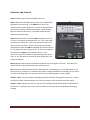
1
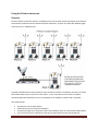
Teletics
Installation and
User Guide
Rev 1.2 July 18, 2012
Warning !! – Hearing Protection Required !!
The wintercom produces sound levels high enough to possibly
create permanent hearing damage! This includes tones
generated at power up. Do not power up or operate these units
without wearing adequate hearing protection!
Teletics wintercom Installation and User Guide V1.2 July 18 2012
Page 1
Contents
Technical Support ................................................................................................................................. 3
Statement of Conformity ...................................................................................................................... 3
Safety Notice ......................................................................................................................................... 3
Introduction .......................................................................................................................................... 4
Using the Teletics wintercom................................................................................................................ 5
Recommended Enclosures, Accessories, Cabling and Antennas .......................................................... 7
Connections .......................................................................................................................................... 9
Installation .......................................................................................................................................... 10
Powering up ........................................................................................................................................ 14
Indicators and Controls ....................................................................................................................... 15
Instructions for Use ............................................................................................................................. 16
Troubleshooting .................................................................................................................................. 16
wintercom 58 Specifications ............................................................................................................... 22
Warranty Statement: .......................................................................................................................... 22
Teletics wintercom Installation and User Guide V1.2 July 18 2012
Page 2
Technical Support
For assistance with any Teletics product, please call us or visit our website.
U.S. Technical Support
(916) 947-7444
Website
www.teletics.com/support
Statement of Conformity
Note: This equipment has been tested and found to comply with the limits for a Class A digital device,
pursuant to part 15 of the FCC and ICES-003 Rules. These limits are designed to provide reasonable
protection against harmful interference when the equipment is operated in a commercial environment.
This equipment generates, uses, and can radiate radio frequency energy and, if not installed and used in
accordance with the instruction manual, may cause harmful interference to radio communications.
Operation of this equipment in a residential area is likely to cause harmful interference in which case the
user will be required to correct the interference at his own expense. Modifications not expressly
approved by the manufacturer could void the user’s authority to operate the equipment under FCC
rules.
This device complies with Industry Canada license -exempt RSS standard(s). Operation is subject to the
following two conditions: (1) this device may not cause interference, and (2) this device must accept any
interference, including interference that may cause undesired operation of the device.
FCC ID: CTO-WINT
Industry Canada: 10253A
Safety Notice
Warning !! – Hearing Protection Required !!
The wintercom produces sound levels high enough to possibly create
permanent hearing damage! This includes tones generated at power up.
Do not power up units without wearing ear protection!
Teletics wintercom Installation and User Guide V1.2 July 18 2012
Page 3
Introduction
The Teletics wintercom is a wireless Phone, Data, and Public Address system designed for use with
temporary or mobile camps. These situations require that basic on site communications between
buildings has to be set up quickly and reliably. The wintercom provides this functionality without the
need to run any wire or cable between buildings.
The wintercom system can be used on its own, or connected to other communications systems that
provide “backhaul” to the outside world, such as satellite communications, or cellular backhaul links.
Key wintercom features:
-
Up to 20 phones can be supported on each radio channel.
-
3 non-overlapping radio channels available.
-
There is no limit to the number of calls that can occur simultaneously on a wintercom system.
-
Each wintercom has an integrated 40WRMS PA amplifier, with preamp output, allowing direct
connection to a PA speaker, or third party amplifier if additional paging power is required.
-
Each wintercom is a complete communications center, which includes connections for one
phone, one computer, and one PA speaker/amp and a NO or NC horn relay.
-
Each system may be programmed with a unique system serial number, in order to prevent
similar systems being operated close together from communicating with each other.
-
Optional Teletics Feature Server RM units can provide “dial 9” capabilities for outside calling
through satellite, cellular, landline,or other backhaul communications systems to 4 wintercom
stations
-
Call Waiting and Call Display features are standard.
-
Camp wide Public Address feature when used with a Teletics Feature Server or Feature Server
RM unit.
-
+24VDC operation.
-
5.8 GHz radios w/ 400 mW radio power output.
-
Simple programming using Teletics TUtil wintercom 58 programming software.
-
Encrypted, spread spectrum radio technology provides security.
-
Units can be added, removed, or moved from any system to another system with TUtil
wintercom 58 programming software.
Teletics wintercom Installation and User Guide V1.2 July 18 2012
Page 4
Using the Teletics wintercom
Overview
Once the Teletics wintercom system is installed, you can call any other wintercom phone, the computers
connected to the wintercom can communicate with each other, and you can send Public Address pages
across all units, or individual units.
A typical installation has as many wintercom units as there are shacks or temporary structures or trailers
that need to have service, and a unit in each trailer. In turn, each wintercom unit has an outdoor
antenna and RF cable attached to it, plus a PA speaker (or PA amplifier), a phone and a computer.
The system allows:
•
•
•
•
any phone to call any other phone
shared internet access across all computers
any phone to page any or all phones. (See Teletics Feature Server or Feature Server RM manual)
any or all users to join a conference call at the site (See Teletics Feature Server Manual)
Teletics wintercom Installation and User Guide V1.2 July 18 2012
Page 5
Telephone to Telephone
If you want to call another phone on the system, you simply pick up a phone on the system and dial the
two digit extension of the person you wish to call. wintercom extensions are two digits, numbered from
11 to 30. If you are at extension 15, and you wish to call extension 20, you simply pick up your phone
and dial 20. You will hear a few seconds silence, then the familiar ringing tone when the phone starts to
ring at the other end.
Call Waiting Feature
Once a conversation is in progress between two phones on the system, you will notice that anyone
wishing to reach either extension currently in use will cause a tone to interrupt the conversation that
you are having. This tone is called a “Call Waiting Tone”. If the person who hears the Call Waiting Tone
hangs up their current call, they can then pick up their phone again and talk to the other person who is
calling them.
Outbound / Inbound Calling
If the system is equipped with a Feature Server RM unit, wintercom units from 11 through 14 can access
an outside line through adding a 9 digit at the beginning of the number being dialed. For instance, if you
wish to dial (713) 555-1212, you would pick up your phone and dial 97135551212. Notice that you do
NOT dial 9 and then wait for a second dial tone. You need to enter the phone number completely,
including the leading 9 digit at one time.
Each of the 4 outside lines on the Feature Server RM is dedicated to one wintercom phone on the
system. When a wintercom phone 11,12,13, or 14 dials a number with a 9 prefix, its dedicated, Feature
Server RM phone line is used, and when the same Feature Server RM line rings on inbound calls, the call
will be directed only to that phone. There is a “one to one mapping” between the Feature Server RM
line ports and the wintercom unit it works with.
Connecting a PA amplifier or 8 ohm PA Speaker
Each wintercom has a 4 position barrier strip that allows you to connect to an amplifier via a 600 Ω
output, or directly to an 8 ohm PA speaker. You require one Teletics Feature Server in each system for
PA to work. The LINE OUT output is 600 ohm, 1 Vpp. The PA 8 Ω output is 40WRMS.
In order to send a PA message out across the entire system, you can pick up any handset in the system,
and dial *99 and after waiting for a few seconds for a connection, you can make your announcement.
You may page individual stations by dialing their respective station number, but with a star as the
leading digit. For example, picking up any phone in the system and dialing *15 would send a page to the
PA speaker attached to wintercom 15.
Teletics wintercom Installation and User Guide V1.2 July 18 2012
Page 6
Data Connections
Each wintercom has an Ethernet port for use with a computer. All wintercom units in a system act as a
common hub, sharing the available bandwidth on the system.
The Ethernet connection provided by a wintercom system is completely transparent to anything else
being sent over the network. You should simply treat it as a “wireless wire”. The data speed for the
wintercom system is 12 Mbps. This is similar to standard office Ethernet speeds on 10BT Ethernet, and
this connection is always faster than the internet connection backhaul provided by satellite or cellular
that is provided to the site.
Recommended Enclosures, Accessories, Cabling and Antennas
The number one support issue we encounter is with choices of antennas, cabling, and proper installation
to prevent water from getting inside RF connectors. Understanding the type of antenna required for the
installation is critical to a successful installation.
The wintercom is designed either for use indoors with a short length (~25 feet) of LMR400 cable to the
outside, or to be placed in an outdoor weatherproof enclosure with a permanently mounted, sealed
base style omni-directional antenna on the top of the enclosure with an antenna coupler between the
antenna and wintercom, and the connections for data, PA Speaker and either a Teletics supplied power
supply or third party power supplies inside. There are also some outdoor telephones that can house the
wintercom inside, such as the Guardian Telecom model WTT-30 or similar. There are numerous outdoor
enclosure companies, such as Stahlin, or if Divisional ratings are required for explosive environments, A
company called Adalet manufactures explosion proof enclosures and has models which the wintercom
will fit inside. Mounting the wintercom is as easy as removing the rubber feet from the bottom of the
unit. The threaded holes in the bottom accommodate 6-32 screws that penetrate inside the enclosure
by ½” or less. The bottom threaded holes contain the rubber feet, and have hard stops after ½”
penetration. Continuing to tighten or force a screw into the wintercom beyond this depth will damage
the wintercom enclosure and possibly the electronics inside.
If the radio is operated indoors with RF cable, Teletics recommends a good quality RF cable capable of
6GHz or better operation, with losses of less than 10dB per hundred feet. Many of our installations have
only 3 dB cable loss between the wintercom and antenna. For example, we have had great success with
LMR-400 and LMR-400 ultraflex in colder climates, on drilling rig sites with less than 25 feet of cable
between the wintercom and the outdoor antenna.
Another common failure is custom RF cables with cheap connectors, badly installed connectors, or cable
assemblies that are not swept to ensure proper operation at the frequencies which the wintercom
operates. It is highly recommended that RF cables are purchased from a distributor with the capability
to test the cable at the frequency of operation used with any Teletics equipment. Additionally, if the
Teletics wintercom Installation and User Guide V1.2 July 18 2012
Page 7
wintercom system is rented and moved, that antennas and cables be tested again as the equipment is
returned prior to being dispatched to the field a subsequent time. If your organization does not have
the capability of testing RF cables at 6 GHz, we strongly recommend an outdoor enclosure mounted
approach to installing your wintercoms, as cable failures are our most significant support issue.
A qualified RF designer can quickly determine cable and antenna types for a good quality link. When in
doubt, our Teletics distributors can assist you with antenna and cable selection.
Teletics has found that most of our customers have previous experience with third party power supplies,
and have chosen a vendor that they already trust. Please choose a power supply capable of delivering at
least 3.5A continuous at a regulated +24VDC output +/- 5% capable of operation over the anticipated
operating temperatures. One of the third party power supplies that Teletics has tested is the Meanwell
AD-155B power supply, which includes a simple charging circuit for charging a +24V Sealed Lead Acid
battery. Optionally, Solar power could also be used, assuming the use of +24VDC solar systems.
When running cables from an indoor to outdoor environment, self fusing rubber tape should be applied
to RF connectors exposed to the elements, as well as proper “drip loops” need to be installed where the
any cable enters the trailer or building wall. Your Teletics distributor can assist you if you have no
previous experience with self fusing rubber tape, or need to purchase some.
Warning !! – Possible Damage to Equipment / Equipment Failure !!
ALL antenna or cable connectors exposed to weather MUST MUST MUST
have proper Self Fusing Rubber Tape ONLY used to ensure water does not
enter the connectors!!! Failure to do this will cause the system to fail!!!
Please do not substitute other types of tape or sealing methods on RF
connectors. Only Self Fusing Rubber tape designed for RF use will work.
Teletics wintercom Installation and User Guide V1.2 July 18 2012
Page 8
Connections
The wintercom back connector panel looks like this:
Connectors are:
DATA is for connection to either a computer or a computer network. The DATA ports on all units in a
wintercom system act like a computer hub. There is no routing between them, and each unit has equal
priority.
PHONE is where the phone plugs in. Any standard phone capable of being used on a POTS line (like your
phone at home) may be used with the wintercom. You may also put up to 5 standard phones in parallel
with this phone connection, if desired, but keep in mind that these phones will work identically to home
phones in parallel on one shared phone line. There will be no privacy and anyone picking up the
additional handsets can hear the conversation, or join it.
RELAY connections are C for Common, NC for Normally Closed and NO for Normally Open. Most devices
that are used for informing that the phone is ringing will use the C and NO pins to form a circuit that will
close when the phone is ringing. If you want to turn off a device when the phone is ringing, you need to
connect the C and NC pins. Please note the maximum current and voltage ratings on the wintercom for
this relay.
+24VDC is for providing power to the unit. If you look closely, you will notice that the screw terminals
indicate which is positive and which is negative. The wintercom requires +24VDC and at least a 3.5A
power supply. If you are using a power supply other than the unit supplied by Teletics, it is strongly
recommended that you use a commercial grade switching power supply suitable for the power
situations that the unit might encounter. Accidentally reversing polarity will not damage the unit, but it
will not operate in this condition.
Teletics wintercom Installation and User Guide V1.2 July 18 2012
Page 9
SPEAKER 600Ω + - is for connection to an external PA amplifier. This is a 1Vpp analog input that is
compatible with almost any PA or audio amplifier. This output may be left unterminated if not used.
SPEAKER 8Ω + - is for connection to an 8 ohm speaker or 8 ohm PA speaker. The integrated amplifier in
the wintercom is 40WRMS. You will typically find considerably higher volume is typically produced by a
PA speaker, rather than a speaker designed for music. For this reason, an 8 ohm PA speaker is
recommended. This output is open circuit protected and should be left unterminated or open if it is
not used.
The ANTENNA connection is not labeled, and is by itself at the opposite end of the wintercom. It is for
use with an antenna rated for 5.8GHz operation. Please contact your Teletics distributor for additional
antenna and RF cable assemblies made to your requirements. This connector is a standard N Female.
Installation
The wintercom system is architected to be a “star topology”. In each system, there needs to be one
master (Unit 11), and up to 19 stations numbered 12 through 30. A system may contain as few as 2
wintercom units, or as many as 20.
Each wintercom station needs to have radio line of sight to the wintercom master.
wintercom Stations do not have to have RF line of sight to each other, only the master.
Teletics wintercom Installation and User Guide V1.2 July 18 2012
Page 10
If there is a Teletics Feature Server as part of the system, it should be attached to the MASTER
wintercom at phone 11, or the MASTER wintercom at phone 11 should have its ethernet port attached
to the switch that provides outside connectivity to the main site and the Teletics Feature Server should
be connected to the main switch.
Here is an example wintercom installation scenario:
An oil drilling rig operation has one VSAT terminal with 4 outside lines, plus an internet connection for
the camp, located in one of the trailers. There are 5 trailers in total, plus a phone on the drilling rig
“doghouse” and one other outside phone on the mud separator platform. There is a requirement for a
PA connection at each location, plus a requirement to have phones 11, 12, 13 and 14 to be able to dial
out over the VSAT system.
This example system requires the following equipment:
7 wintercom units, one programmed as a Master, the other 6 as stations
1 Teletics Feature Server RM unit
TUtil wintercom 58 Programming Software
The TUtil wintercom 58 programming software can be downloaded from the Teletics website. Here is
how you do this:
Obtaining / Installing Teletics TUtil wintercom 58 software:
1. To assist you in deciding which computer you would like to load TUtil wintercom 58 on at your
shop, you should be aware that TUtil wintercom 58 performs best on a computer with one
Ethernet port and Windows 7 Professional.
2. Laptop setup:
a. When running TUtil wintercom 58, you need to temporarily disable the Windows
firewall and virus checking.
b. Ensure that the laptop that you are using is not putting the Ethernet port to sleep as a
power saving feature. If the Ethernet port goes to sleep during programming, it will
cause TUtil wintercom 58 to hang.
c. In rare cases, it is necessary to turn off the automatic cable detection feature in the
Laptop chipset’s drivers. The Ethernet port on the wintercom units have this feature
turned on, and occasionally the wintercom and laptop will both attempt to switch back
and forth and neither will ever settle on the correct setting.
Teletics wintercom Installation and User Guide V1.2 July 18 2012
Page 11
3. Once you have a computer ready, preferably with Windows 7 installed, you should obtain the
software by doing the following:
a. Open up “My Documents” in windows.
b. Enter ftp://teletics.com in the address bar. Press the enter key, or hit the “go” button.
c. You should now be at the Teletics FTP site. You need to look for the software package
TUtil wintercom 58.
d. Complete installation and use instructions for TUtil wintercom 58 are in the TUtil
wintercom 58 manual.
For any wintercom system to correctly operate, you will need to program one wintercom as unit 11.
The rest can be programmed as any number from 12 through 30, however you cannot have two
wintercom units with the same number in one system. A system may contain up to 20 wintercom units.
Each wintercom unit has its own serial number that is assigned at the factory. This is on the label of
each unit. Additionally, the TUtil wintercom 58 programming software allows you to set a Group ID as
well, which is a common identity code which is used to group units into one system together. The
Group ID can be any alpha numeric sequence you would like, up to 10 characters or numbers.
When Teletics wintercom systems leave the factory, they are tested and shipped as systems with one
master and 4 stations. They are numbered 11, 12, 13, 14, and 15, and the Group ID for the system is the
same as the serial number for the Unit 11 master. The factory default channel is channel A and the LAN
and dial 9 features are also turned on by default during factory programming. These systems may be
deployed right out of the carton as a 5 station system.
However, for example, let’s assume that we have a brand new wintercom system in its carton in our
shop, and we have two additional “loose” units that we want to make into one 7 station system. For our
example let’s assume that they have the following serial numbers:
Complete System:
Unit
Serial Number
Group ID
Unit 11
0805-0360
0805-0360
Unit 12
0805-0361
0805-0360
Unit 13
0805-0362
0805-0360
Unit 14
0805-0363
0805-0360
Unit 15
0805-0364
0805-0360
Teletics wintercom Installation and User Guide V1.2 July 18 2012
Page 12
Loose Units:
Unit 12
0802-0301
unknown
Unit 14
0802-0303
unknown
Therefore, the fastest way to program our example system is to program the loose units to Unit 16 and
Unit 17 using TUtil wintercom 58, using the Group ID of the new, complete system, which is 0805-0360.
Also, keep in mind that you should use the TUtil factory default channel of Channel A. If you wish, you
can disable the LAN port on the unit, so that your customer cannot connect a computer to the unit.
Setting the dial 9 option to off
One other way to accomplish the same thing is to reprogram all of the units using a serial number of
your choice, such as A1B2C3D4, or SITE4567.
Keep in mind that all serial numbers are case sensitive!
It is noteworthy that Teletics Feature Server and Feature Server RM units do not require any kind of
programming. They will only talk to the system that they are physically connected to. However, the
Feature Server RM may be modified to even add new system features or change even basic elements of
how the system operates. This is beyond the scope of this manual. For further details on the Feature
Server custom programming options, please refer to the Teletics RM Manual and the Teletics Feature
Server Handbook.
Once you have the wintercom units programmed, it is a good idea to test them as a system to ensure
that each unit can call the other units in the system. You connect one of the units to the Teletics
Feature Server unit, and once you have antennas and phones connected to each unit, you should apply
power to all of them. You can refer to the “Powering Up” section on what the LEDs on the front panel
mean.
Once all of the wintercom units can call each other, you can attach PA speakers to their outputs and try
doing a PA message across the system. Be warned that the volume produced by multiple wintercom
units on one bench can be a bit overwhelming. You should start with the Volume at about a quarter and
try paging one wintercom at a time and go from there. You should also be warned that the power up
sequence produces an “ok” tone on each unit during power up, to ensure that the PA speaker is
connected correctly and is operating properly. If you aren’t expecting this, it can certainly replace your
morning cup of coffee…
Finally, once the complete system is working on a phone to phone or PA basis, you can then attach the
phone lines to the line ports on the Feature Server RM and test the functionality of the outside phone
lines.
Teletics wintercom Installation and User Guide V1.2 July 18 2012
Page 13
Powering up
Warning !! – Hearing Protection Required !!
The wintercom produces sound levels high enough to possibly create
permanent hearing damage! This includes tones generated at power up.
Do not power up units without wearing ear protection!
Once all wintercom units are connected to antennas, speakers, phones and computers, you can power
them up. You can power the system up in any order. Additionally, even if any unit is accidentally
powered down, it will return to normal operation once it is powered back on and has time to completely
initialize. There is never a requirement to power up units in a particular order. This is a feature of the
system design, since most remote work environments have generated power that tends to be
intermittent.
In most cases, it is prudent to use some sort of power conditioning product in line with the power
adapter for the wintercom. A good quality power bar that has an equipment replacement guarantee is
generally a good investment, and can be used to protect the other equipment already in the trailer.
Warning !! – Possible Damage to Equipment !!
Powering up a wintercom unit without having an antenna connected will
damage it! You MUST connect a 5.8 GHz antenna to the unit before
powering it up!
Teletics wintercom Installation and User Guide V1.2 July 18 2012
Page 14
Indicators and Controls
Power indicates power has been applied to the unit.
Radio indicates that the Radio section of the unit is powered up
and appears to be working. If the Radio LED is not on, the
wintercom will not work properly in a system. You should check
that the unit has been properly programmed. If programming
does not make this LED turn on, you should assume that the
wintercom needs servicing.
LAN indicates that there is an active LAN connection to the unit,
ie. There is a computer connected and it is on. This is the status
of the physical connection. It does not indicate that there is an
active internet connection. In fact, if the wintercom has been
programmed to have the LAN Port disabled, this LED will still turn
on. It simply means the wiring is correct. If there is no computer
connected to the LAN port, this LED will not be on. The
wintercom may still be used for PA and phone operation in this
state, ie., this LED does not need to be on for phone calls or PA
services to operate.
Phone indicates that the phone attached to the wintercom unit has gone “off hook”. This shows you
that the phone is correctly attached to the wintercom unit.
PA illuminates to indicate that the Teletics Feature Server is attempting to set up a PA broadcast to the
wintercom unit. PA will turn on solid once the system is ready to broadcast the message. Once PA turns
on solid, the sending wintercom unit user will hear a tone indicating that it is time to speak.
Volume – Voice This control adjusts the paging volume for the voice message for this one user. It does
not affect any other volume settings in the rest of the system, or for any other unit in the system.
Volume – Tones adjusts the volume of ring tone that is played through the PA speaker attached to this
unit when it is receiving a call, as well as the introductory tone upon power up and before the paging
message.
Teletics wintercom Installation and User Guide V1.2 July 18 2012
Page 15
Instructions for Use
Once all wintercom units have power applied, and they have had about a half minute to initialize, you
may pick up any phone in the system and dial any other phone in the system. The initial tones at power
up are there to indicate that the PA system is properly working and connected to a speaker.
The system allows as many simultaneous phone conversations as there are phones. For example, if you
have 6 phones on the system, you can have 3 phone conversations going on at once.
Inside Phone numbers range from 11 to 30. If you attempt to call a phone that isn’t in the system, you
will receive a busy signal back in about 45 seconds.
If you have a Feature Server RM in the system, their outside lines can be reached using a leading “9”
along with the number with calls place from wintercoms 11,12,13, or 14.. Keep in mind that if the
outside line you are using also requires a “9” to get an outside line, you will need to dial another “9” as
“99” before the actual number, since the Feature Server RM strips off the first “9” and then dials the
number. The user would have to dial 997135551212, for example. If the outside line is “straight out”,
then 97135551212 would be correct.
Troubleshooting
It is important to know the following:
-
Dial tone is locally generated at each wintercom unit. It does not indicate a phone line is
working somewhere else in the system.
-
If you pick up a phone attached to a wintercom and get a busy signal prior to dialing a number,
or if you get a recorded message saying “device not registered” it has either not completed its
power up cycle, is not properly programmed, or has an issue connecting to the master due to a
bad radio cable, antenna, an RF path that is obstructed, or a radio failure.
-
We have not yet found a standard telephone that does not work with the wintercom. However,
a phone may have the wrong settings, or may not be designed to work on a standard POTS
(home) phone line.
-
Some older phones have “pulse” and “tone” settings. Almost every phone in the world
today uses “tone”. A phone with a “pulse” dial setting will not work.
-
Some digital phones are designed for use only with office digital PBX systems. When in
doubt, check the phone in question with a standard POTS (home) phone line, or a phone
line in your office dedicated for use with a FAX machine.
Teletics wintercom Installation and User Guide V1.2 July 18 2012
Page 16
-
The wintercom phone jack may also be used to power such things as horn relays, etc. Again, we
have not encountered any of these that do not work when installed according to their
manufacturer’s instructions.
-
When using outside lines, it is important to understand how they work relative to what you
expect. For instance, if you have to dial an access code or a 9 prior to dialing out on a particular
phone line, you will need to put these codes into the dial sequence with another 9 in front to
access the line. When in doubt, it is always best to try dialing out on the outside line with a
conventional phone prior to trying it with a Feature Server RM unit.
-
Using the wintercom 58 with a cordless phone system of a similar 5.8 GHz frequency is not
recommended. Most manufacturers of these phones do not provide specifications on the exact
frequency that they use, therefore it is impossible for us to determine which channels you
should program into your wintercom units. A more suitable technology for a cordless phone is
the newer DECT standard, or another frequency, such as 900 MHZ with a 5.8 GHz wintercom.
-
When you make a phone call from one wintercom to another, how the dial tone behaves can
provide some troubleshooting information:
-
If you get a busy signal within 5 seconds of dialing another wintercom extension, either
that wintercom extension is busy, or you have tried to dial a number that isn’t in the
system. Such as trying to dial extension 33, for example.
-
If the line goes quiet for about 30 seconds, then you get a busy signal, the extension
could not be reached. The most typical reason for this is a problem with either the
serial numbers not being identical in the units, or a radio related problem.
-
If the line goes quiet for over one minute, and you do not ever hear a ring or busy, you
should check if the Call LED is illuminated at the wintercom unit that you are trying to
call. It will most likely be on, indicating that the system has made the connection, but
either the phone or phone cable at the phone you are calling is at fault.
Radio problems generally show up as either inability to call from one wintercom to another, or the call
dropping within the first minute. What happens when the call drops is that either one end or both ends
hears the conversation abruptly end, followed immediately by dial tone. This problem can be caused by
a number of issues, including:
-
Bad antenna(s)
-
Water inside the antenna(s)
-
Cabling related issues
Teletics wintercom Installation and User Guide V1.2 July 18 2012
Page 17
-
Poor quality connectors
-
Cross threaded connector on wintercom and cable
-
Bad cable assembly practices
-
Cable assemblies not tested / rated for frequency of operation
-
Bad antenna model selection for the site in question
-
Questionable radio line of sight to master wintercom
-
Interference in the same frequency used by the wintercom system
-
A bad radio in the wintercom unit
The best way to diagnose a radio path problem is to dial the master from each wintercom unit. If you
can maintain a phone call for longer than one minute consistently between any unit and the master, you
can assume that the master working properly, and continue diagnosing the radio path for each
additional unit. Additionally, there is a radio signal strength tool for field use called TUtil wintercom 58,
which can be downloaded from the Teletics website.
TUtil wintercom 58 can be run on a laptop connected to the wintercom system master unit, and it will
display the signal strength for each wintercom unit on the system.
It is also important to understand that once one wintercom can call another wintercom, the data
portion of the wintercom is operating. Telephone calls use exactly the same radio path and
programming that the Ethernet port on the wintercom uses. In essence, the phones are just an
extension to the data network.
However, if you are experiencing problems accessing the internet try pinging one of the other
computers or routers on the wintercom system first. To do this, go to a computer on the wintercom
system, and open up a command prompt window. (Usually under Start, Programs, Accessories,
Command Prompt.)
Type this command: ipconfig
You should see some basic network addresses, and more importantly, something called a default
gateway address:
Teletics wintercom Installation and User Guide V1.2 July 18 2012
Page 18
First, you should ping the IP address:
Ping 192.168.1.100 (or whatever numbers you see next to IP Address when you ran ipconfig):
If you get a reply back from the IP address, it means your network port in the computer seems to be
working. Next try to ping your default gateway address:
Ping 192.168.1.69 (again, use whatever numbers are next to Default Gateway on your computer):
Teletics wintercom Installation and User Guide V1.2 July 18 2012
Page 19
If you get a reply back, the gateway on the network is connected to the computer you are working on,
and the wintercom units are working correctly. However, there are a number of other settings that you
need for each computer (and some from your internet service provider) to get to the point where you
can “surf the internet”.
Assuming that everything works so far, try:
Ping www.yahoo.com:
Teletics wintercom Installation and User Guide V1.2 July 18 2012
Page 20
If you get a reply back, you should be okay to assume that the internet connection is fine at the
computer you are currently working on. If this ping produces an error, you can assume that there is
something wrong with the DNS addresses settings in the “Network Settings” section of Windows. Your
internet service provider might be able to assist you with what these settings should be.
Keep in mind that the wintercom system behaves exactly like an Ethernet cable does. Also, if you can
make a phone call between all the wintercom masters and stations, any networking problems are
usually the result of settings in Windows on the computers, or how the internet access and routers are
programmed.
In general, if you can phone between stations, the next person to give you help would be the satellite
provider, or whoever is providing internet access to the site.
Teletics wintercom Installation and User Guide V1.2 July 18 2012
Page 21
wintercom 58 Specifications
Phone Connector
Standard RJ-11
Data Connector
Standard RJ-45
Antenna Connector
N Female
Radio Type
5.8 GHz DSSS License Free
Radio Output Power
400 mW / +26 dBm
Radio Receive Sensitivity
-89 dBm @ 10 -5 BER
Maximum Range
25 kms / 15 Miles
Power Required
+24VDC @ 3.5A
Operating Temperature Range
-20C to +50 C / -5F to +125 F
Dimensions
6.75” x 5.25” x 1.95”
Shipping Weight, including packaging
3.8 kgs / 8.4 lbs
Mounting Holes (approx.)
5.3” x 4.6”
Warranty Statement:
Teletics warrants the wintercom to be free of defects of materials and workmanship for a period of one year after
purchase by the original owner.
Teletics will repair or replace, at its option, any wintercom unit that fails to perform the task it was designed for
under normal use, provided the wintercom is returned, at the cost of the owner, to Teletics, or one of Teletics
Authorized Repair Facilities in the United States or Canada. Items returned for repair must be accompanied with a
problem description and original proof of purchase, such as an invoice.
Any operation of the wintercom outside of specified temperatures, specified input power, environment, or in a
manner specified as harmful in this manual will void any warranty. Additionally, any attempted repair or
dismantling of any Teletics product, in any way, will void all warranties.
In no event shall Teletics liability exceed the original purchase price of the product from direct, indirect, special,
incidental, or consequential damages from the use, or misuse of this product.
Intended Use Statement:
This product is intended for industrial communications use. Installation is to be performed by qualified Radio
Technicians.
Teletics wintercom Installation and User Guide V1.2 July 18 2012
Page 22