1
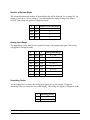
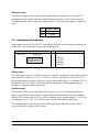
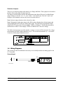
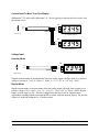
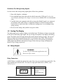
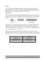
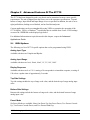
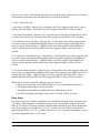
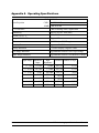
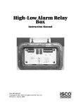
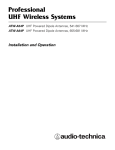
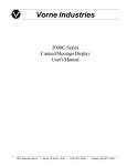
Vorne Industries 87/719 Analog Input Module User's Manual 1445 Industrial Drive • Itasca, IL 60143-1849 • (630) 875-3600 • Telefax (630) 875-3609 . 3 Chapter 1 Introduction . . . . . . . . . . . . . . . . . . . . . . . . . . . . . . . . . . . . . . . . . . . . . . . . . . . . . 1.1 Accessing Wiring Connections And Selection Switches . . . . . . . . . . . . . . . . . . . . . . 3 1.2 Setting The DIP Switches For Your Application . . . . . . . . . . . . . . . . . . . . . . . . . . . . . . 3 Run and Program Modes . . . . . . . . . . . . . . . . . . . . . . . . . . . . . . . . . . . . . . . . . . . . . . . . . . . . . . . . . . . . . . 3 DIP Switch Settings . . . . . . . . . . . . . . . . . . . . . . . . . . . . . . . . . . . . . . . . . . . . . . . . . . . . . . . . . . . . . . . . . . . . 4 Analog Mode . . . . . . . . . . . . . . . . . . . . . . . . . . . . . . . . . . . . . . . . . . . . . . . . . . . . . . . . . . . . . . . . . . . . . . . . . . 4 Number of Decimal Digits . . . . . . . . . . . . . . . . . . . . . . . . . . . . . . . . . . . . . . . . . . . . . . . . . . . . . . . . . . . . . . 5 Analog Input Range . . . . . . . . . . . . . . . . . . . . . . . . . . . . . . . . . . . . . . . . . . . . . . . . . . . . . . . . . . . . . . . . . . . 5 Smoothing Factor . . . . . . . . . . . . . . . . . . . . . . . . . . . . . . . . . . . . . . . . . . . . . . . . . . . . . . . . . . . . . . . . . . . . . 5 Display Format . . . . . . . . . . . . . . . . . . . . . . . . . . . . . . . . . . . . . . . . . . . . . . . . . . . . . . . . . . . . . . . . . . . . . . . 6 1.3 Analog Input Connectors . . . . . . . . . . . . . . . . . . . . . . . . . . . . . . . . . . . . . . . . . . . . . . . . . . . 6 Analog Input . . . . . . . . . . . . . . . . . . . . . . . . . . . . . . . . . . . . . . . . . . . . . . . . . . . . . . . . . . . . . . . . . . . . . . . . . . . 6 Auxiliary Input . . . . . . . . . . . . . . . . . . . . . . . . . . . . . . . . . . . . . . . . . . . . . . . . . . . . . . . . . . . . . . . . . . . . . . . . . 6 Selection Jumpers . . . . . . . . . . . . . . . . . . . . . . . . . . . . . . . . . . . . . . . . . . . . . . . . . . . . . . . . . . . . . . . . . . . . . 7 1.4 Wiring Diagrams . . . . . . . . . . . . . . . . . . . . . . . . . . . . . . . . . . . . . . . . . . . . . . . . . . . . . . . . . . . . 7 Current Input . . . . . . . . . . . . . . . . . . . . . . . . . . . . . . . . . . . . . . . . . . . . . . . . . . . . . . . . . . . . . . . . . . . . . . . . . . 7 Current Input To More Than One Display . . . . . . . . . . . . . . . . . . . . . . . . . . . . . . . . . . . . . . . . . . . . . . 8 Voltage Input . . . . . . . . . . . . . . . . . . . . . . . . . . . . . . . . . . . . . . . . . . . . . . . . . . . . . . . . . . . . . . . . . . . . . . . . . . 8 Unipolar Mode . . . . . . . . . . . . . . . . . . . . . . . . . . . . . . . . . . . . . . . . . . . . . . . . . . . . . . . . . . . . . . . . . . . . . . . . . 8 Bipolar Mode . . . . . . . . . . . . . . . . . . . . . . . . . . . . . . . . . . . . . . . . . . . . . . . . . . . . . . . . . . . . . . . . . . . . . . . . . . 8 Guidelines For Wiring Analog Signals . . . . . . . . . . . . . . . . . . . . . . . . . . . . . . . . . . . . . . . . . . . . . . . . . . 9 1.5 Scaling The Display . . . . . . . . . . . . . . . . . . . . . . . . . . . . . . . . . . . . . . . . . . . . . . . . . . . . . . . . . 9 1.6 Relay Output . . . . . . . . . . . . . . . . . . . . . . . . . . . . . . . . . . . . . . . . . . . . . . . . . . . . . . . . . . . . . . . 9 Relay Connectors . . . . . . . . . . . . . . . . . . . . . . . . . . . . . . . . . . . . . . . . . . . . . . . . . . . . . . . . . . . . . . . . . . . . . . 9 Presets . . . . . . . . . . . . . . . . . . . . . . . . . . . . . . . . . . . . . . . . . . . . . . . . . . . . . . . . . . . . . . . . . . . . . . . . . . . . . . . 10 Activate Relay . . . . . . . . . . . . . . . . . . . . . . . . . . . . . . . . . . . . . . . . . . . . . . . . . . . . . . . . . . . . . . . . . . . . . . . . 10 Chapter 2 Advanced Features Of The 87/719 . . . . . . . . . . . . . . . . . . . . . . . . . . . . . . . . 11 2.1 VDP4 Options . . . . . . . . . . . . . . . . . . . . . . . . . . . . . . . . . . . . . . . . . . . . . . . . . . . . . . . . . . . . . 11 Analog Input Type . . . . . . . . . . . . . . . . . . . . . . . . . . . . . . . . . . . . . . . . . . . . . . . . . . . . . . . . . . . . . . . . . . . . 11 Analog Input Range . . . . . . . . . . . . . . . . . . . . . . . . . . . . . . . . . . . . . . . . . . . . . . . . . . . . . . . . . . . . . . . . . . 11 Display Response . . . . . . . . . . . . . . . . . . . . . . . . . . . . . . . . . . . . . . . . . . . . . . . . . . . . . . . . . . . . . . . . . . . . 11 Top Side Settings . . . . . . . . . . . . . . . . . . . . . . . . . . . . . . . . . . . . . . . . . . . . . . . . . . . . . . . . . . . . . . . . . . . . . 11 Bottom Side Settings . . . . . . . . . . . . . . . . . . . . . . . . . . . . . . . . . . . . . . . . . . . . . . . . . . . . . . . . . . . . . . . . . 11 Preset Mode . . . . . . . . . . . . . . . . . . . . . . . . . . . . . . . . . . . . . . . . . . . . . . . . . . . . . . . . . . . . . . . . . . . . . . . . . . 11 87/719 Analog Input Module Users Manual 1 Relay Setup . . . . . . . . . . . . . . . . . . . . . . . . . . . . . . . . . . . . . . . . . . . . . . . . . . . . . . . . . . . . . . . . . . . . . . . . . . 12 Display Lead In Character . . . . . . . . . . . . . . . . . . . . . . . . . . . . . . . . . . . . . . . . . . . . . . . . . . . . . . . . . . . . 13 Display Trailer Character . . . . . . . . . . . . . . . . . . . . . . . . . . . . . . . . . . . . . . . . . . . . . . . . . . . . . . . . . . . . . 13 Over Range Indicator . . . . . . . . . . . . . . . . . . . . . . . . . . . . . . . . . . . . . . . . . . . . . . . . . . . . . . . . . . . . . . . . . 13 Under Range Indicator . . . . . . . . . . . . . . . . . . . . . . . . . . . . . . . . . . . . . . . . . . . . . . . . . . . . . . . . . . . . . . . . 13 Display Precision . . . . . . . . . . . . . . . . . . . . . . . . . . . . . . . . . . . . . . . . . . . . . . . . . . . . . . . . . . . . . . . . . . . . . 13 Auxiliary Input . . . . . . . . . . . . . . . . . . . . . . . . . . . . . . . . . . . . . . . . . . . . . . . . . . . . . . . . . . . . . . . . . . . . . . . . 13 Trailing Zeroes . . . . . . . . . . . . . . . . . . . . . . . . . . . . . . . . . . . . . . . . . . . . . . . . . . . . . . . . . . . . . . . . . . . . . . . 13 Appendix A Operating Specifications . . . . . . . . . . . . . . . . . . . . . . . . . . . . . . . . . . . . . . . 14 Notice Of Disclaimer While the information in this manual has been carefully reviewed for accuracy, Vorne Industries, Inc. assumes no liability for any errors, or omissions in the information. Vorne Industries also reserves the right to make changes without further notice to any products described in this manual. 2 87/719 Analog Input Module Users Manual Chapter 1 Introduction The 87/719 Analog Module is a plug-in module for an 87/232 Series Display. The Analog Module incorporates a 16 bit Sigma-Delta (Charge-Balancing) Analog to Digital converter. The unit features Auto-zero, a internal precision voltage reference which allows Auto-calibration and precision resistors with low (5 ppm) temperature coefficient for excellent temperature stability. The unit accepts an analog input, converts it to digital information, scales it in accordance with the top and bottom of range and displays the scaled value. The top and bottom of range can be set serially from a computer using VDP4. VDP4 is a Windows based utility that allows customization of the 87 Series Display. VDP4 is available from Vorne at no charge. 1.1 Accessing Wiring Connections And Selection Switches All external power and communication line connections to the display are made to printed circuit board mounted terminal strips. These terminal strips, as well as a 10 position DIP switch, and COM PORT selection switch, can be accessed by removing the back panel user access plate. WARNING - SHOCK HAZARD Always completely disconnect power from the display before opening the user access plate. Do not reapply power to the display until the access plate has been reinstalled and securely closed. There are two 7/8" conduit openings on the back panel of the display, provided for bringing external wiring into the display enclosure. If these conduit openings will not be used for wiring, these openings can be filled with plastic plugs (Caplugs Part Number BP-7/8) which are provided with the display. The left most conduit opening is provided for power wiring, the right most for signal wiring. It is not recommended to run power wiring and signal wiring in the same conduit! 1.2 Setting The DIP Switches For Your Application Note: Changes to the DIP switches are only acknowledged at power up. Factory default settings are shown in gray. Note: Installing the 87/719 module overrides the DIP switch settings of the 87/232 Logic board. Run and Program Modes 1 Mode ON Program OFF Run 87/719 Analog Input Module Users Manual 3 For normal operation the Run/Program switch should be set to Run (off). Setting the unit to Program mode allows the unit to be customized using VDP4 and to run one of two diagnostic routines. If DIP switch 2 is off, the display cycles thru the following display diagnostic. a. Error status Should show E0. E1 or E2 indicates a memory error. b. Unit Address Default value is 00. c. Red segment test The unit will turn on 1 segment at a time A thru G and DP. d. Green segment test. For a single color display a blank screen will be displayed. e. All segments ON. f. Unit type. 3 = 87/719 g. --. This is a separator between the Unit type and the Software version. h. Software version. This number is displayed on two consecutive screens (Ex: 1.2.5). If DIP switch 2 is on, the display runs a DIP switch diagnostic. This diagnostic displays the HEX value of DIP switches 3 thru 10 (switches 3 to 6 = MSD, switches 7 to 10 = LSD). If switches 3 thru 10 are all set to the ON position, the display turns on all LEDs. DIP Switch Settings For normal operation the Settings DIP switch should be set to VDP4 (off). This allows the unit to scale the display according to the user definable top and bottom of range. If the settings DIP switch is off, switches 3 thru 10 are ignored. The Diagnostic mode is for troubleshooting use. Diagnostic mode allows the unit to respond to the analog input the way a volt or current meter would. The settings of DIP switches 3 thru 10 define how the analog input value is displayed. In program mode, Switch 2 selects between Display test (off) and DIP switch test (on). 2 Settings ON Analog Input Diagnostic OFF VDP4 Analog Mode The Analog Mode setting defines if the analog input signal is Unipolar or Bipolar. Unipolar is used for positive measurements. Bipolar mode is used for measuring positive and negative signals. This setting only applies to Diagnostic mode. 4 3 Analog Mode ON Unipolar OFF Bipolar 87/719 Analog Input Module Users Manual Number of Decimal Digits This setting determines the number of decimal digits that will be displayed. For a setting of 0, the display powers up to 0. For a setting of 3, the unit displays the analog reading in the format X.XXX. This setting only applies to Diagnostic mode. 4 5 Number of Decimal Digits OFF OFF 0 OFF ON 1 ON OFF 2 ON ON 3 Analog Input Range The Input Range setting must be set to match the range of the analog input signal. This setting only applies to Diagnostic mode. 6 7 8 Analog Input Range OFF OFF OFF 0 - 1 mA OFF OFF ON 0 - 20 mA OFF ON OFF 0 - 20 mV OFF ON ON 0 - 1.25 V ON OFF OFF 0-5V ON OFF ON 0 - 10 V ON ON OFF 0 - 100 V ON ON ON 0 - 1 mA Smoothing Factor The smoothing factor averages the analog input signal over several samples. Turning the smoothing Factor on results in a more stable display. This setting only applies to Diagnostic mode. 9 Smoothing Factor ON ON OFF OFF 87/719 Analog Input Module Users Manual 5 Display Format The analog to digital converter represents the analog input as a number between 0 and 65535. Selecting Raw mode displays this representation of the analog input. Cooked mode scales the Raw mode numbers to the Analog Input Range selection. This setting only applies to Diagnostic mode. 10 Display Format ON Raw OFF Cooked 1.3 Analog Input Connectors Analog Inputs can be wired to the 87/719 through the four pins of the Analog port terminal strip (marked P4). The Analog Input terminal strip is shown below. 4 Pin Analog Input Terminal Strip (P4) Pins 1 to 4 Pin Function Analog Input 1 2 3 4 1 Analog IN + 2 Analog IN - 3 GROUND 4 AUX. Input Analog Input The analog input consists of a resistor across the In + and In - terminals for current inputs and low voltage inputs (78 ohm for 0 - 1 mA, 3.9 ohm for 4 - 20 mA, 10K ohm for 10mV and 1V). For higher voltage inputs, the input consists of a voltage divider (20K ohm for 5V, 40K ohm for 10V, and 400K ohm for 100V input). The analog signal is connected to a differential analog input circuit with a programmable gain front end. Auxiliary Input The Auxiliary input has an internal 10K pull-up resistor to +5 volts. Momentarily sinking this input to ground with a contact closure or open collector NPN transistor activates the Auxiliary function. The Auxiliary input is TTL or CMOS compatible with a minimum high of 3.5 VDC and a maximum low of 1.5 VDC. The Auxiliary input is active on the negative going edge. The Auxiliary input can only be used in Peak Hold applications. When the Auxiliary Input is activated, the peak or valley value is cleared. 6 87/719 Analog Input Module Users Manual Selection Jumpers There are two Selection jumpers that must be set; Range and Mode. These jumpers are located to the left of the Analog Input terminal strip (P4). The Range selection jumper specifies the analog input range that will be used. Available Range jumper settings are 10 mV, 1 V, 5 V, 10 V, 100 V, 1 mA, and 20 mA. The 100 V and 1 mA settings are non standard, and can only be used if custom ordered. Note: Only one range selection can be selected at a time. Note: Changing the analog input range in the field requires changing the selection jumper and reprogramming the unit for the new analog input range. The unit can be programmed serially using the RS-232 port of the 87 Series display. VDP4 is a Windows based utility that allows customization of the 87 Series Display. VDP4 is available from Vorne at no charge. The Mode selection jumper specifies whether a voltage or current will be measured. For voltage measurements the Mode jumper should be set to V. For current measurements (0 - 1 mA and 4 20 mA) the Mode jumper should be set to I. 1.4 Wiring Diagrams This section provides the information necessary to successfully interface an analog signal to the 87/719 module. Current Input P4 + - OUT + OUT - Shield Current Source 87/719 Analog Input Module Users Manual IN + 1 IN Ground 2 3 87 SERIES DISPLAY 7 Current Input To More Than One Display Additional 87/719 units can be added onto a 4 - 20 mA signal by wiring the devices in series with the current source. P4 + - OUT + OUT - Shield IN + 1 IN Ground 2 3 Current Source 1ST 87 SERIES DISPLAY P4 IN + 1 IN Ground 2 3 2ND 87 SERIES DISPLAY Voltage Input Unipolar Mode P4 OUT + OUT - Shield Voltage Source IN + 1 IN Ground 2 3 87 SERIES DISPLAY Unipolar measurements are measurements where the analog signal will range from 0 to a positive voltage or current (0 - 1mA, 0 - 20mA, 0 - 10mV, 0 - 1V, 0 - 5V, 0 - 10V or 0 - 100V). Bipolar Mode Bipolar measurements are measurements where the analog signal will range from a negative to a positive voltage (-10 to +10mV, -1 to +1V, -5 to +5V, -10 to +10V, or -100 to +100V). Bipolar ranges are with respect to IN-. The unit is shipped from the factory set for Unipolar mode. Applications requiring Bipolar operation should be custom oredered from the factory. For optimal results R11 should be changed to a 4.7K ohm resistor. 8 87/719 Analog Input Module Users Manual Guidelines For Wiring Analog Signals For best results when wiring analog signals please follow these guidelines: 1. Keep cable length to a minimum. 2. Use a shielded twisted pair cable with the shield connected to GND (pin 3) only at the 87/719 display (floating at the voltage or current source). Belden 9501 is a recommended cable. 3. Carefully check your equipment and cable to ensure that Shield Ground is not connected at both ends of the cable. If there is a significant difference in Earth Ground potential between the two ends of the cable, it could cause reading errors, or even damage to the analog circuitry. 4. Do not run the analog cable parallel to any power cables. 1.5 Scaling The Display The analog input can be scaled to display a user defined span. The Bottom of range corresponds to the lowest valid analog input signal. The top of range corresponds to the highest valid analog signal. The display value will range linearly between the bottom and top of range. The top and bottom of range can be programmed into the 87 Series display using VDP4. When the unit is shipped from the factory, the top and bottom of range are set to the customers specifications. Analog inputs that fall below the bottom of range or above the top of range will display the bottom or top of range respectively. 1.6 Relay Output WARNING Use the relay for annunciator applications only. Do not use it for control. Relay Connectors A SPDT Relay is available through the three pins of the relay port terminal strip (marked P5). The relay terminal strip is shown below. The relay is a single pole double throw (SPDT), rated 120VAC @ 1A. 3 Pin Relay Terminal Strip (P5) A B C 87/719 Analog Input Module Users Manual Pin Function A Normally Closed (NC) B Common C Normally Open (NO) 9 Presets An 87 series display can be programmed to activate the relay when a trigger point is reached (Preset One or Preset Two). The 87 Series Display is shipped from the factory with the Preset function disabled. VDP4 can be used to configure the Preset function. Once the Preset function is enabled, the Presets can be changed using VDP4 or the 87 Terminal. Activate Relay The relay can also be activated serially by using the Relay command. The Relay command string begins with the ASCII character R (52 hex/82 decimal). Note that the R must be upper case, and must be followed by one character (which determines what relay action will occur). The available actions are: Action ASCII Character Hex/Decimal Representation Turn relay on 1 31 hex/49 decimal Turn relay off 0 30 hex/48 decimal Sequence A A 41 hex/65 decimal Relay Sequence A is user definable as either a Delay On Relay or Cycle Relay. VDP4 is required to change this parameter. The Delay On Relay selection allows adjustment of the delay and duration time. These settings are adjustable from .1 to 25.5 seconds. The Cycle Relay selection allows specifying the ON time (.1 to 25.5 seconds), OFF time (.1 to 25.5 seconds), and number of cycles to perform (adjustable from 1 to 255 times). The following examples assume that addressing and checksums are not being used, and that Terminator has been selected as <CR>. Also, note that the header of the packet <SOH>s: has the effect of broadcasting to all displays, overriding any group or individual address a display might be set to. 10 To.... Transmit Turn the relay on <SOH>s:R1<CR> Turn the relay off <SOH>s:R0<CR> Trigger Sequence A <SOH>s:RA<CR> 87/719 Analog Input Module Users Manual Chapter 2 Advanced Features Of The 87/719 The 87/719 has been designed in such a way that it can be customized to meet a users specific requirements. The unit is shipped from the factory set to the customers specifications. Top and bottom of range, Input Mode and Input Range are set as specified. In addition, the unit is set to: right justified data, leading zeroes blanked, and no fixed decimal point. Custom applications can be accommodated by using VDP4 to customize the operation of the 87/719 display. VDP4 is a WindowsTM based utility that is available from Vorne. VDP4 settings are stored in a EEPROM on the displays logic board. For additional information on topics discussed in this chapter, request the Advanced Applications Guide. 2.1 VDP4 Options The following is a list of 87/719 specific options that can be programmed using VDP4. Analog Input Type Available selections are Unipolar and Bipolar. Analog Input Range Available selections are 1mA, 20mA, 10mV, 1V, 5V, 10V, 100V. Display Response Available selections are 0 to 128. A setting of 0 corresponds to a immediate response, a setting of 128 selects a update time of approximately 2 seconds. Top Side Settings Top side settings include the top of range scale value, and the desired top of range analog input value. Bottom Side Settings Bottom side settings include the bottom of range scale value, and the desired bottom of range analog input value. Preset Mode Six Preset Modes are available; None, One Preset Up, One Preset Down, Two Presets Cascade Up, Two Presets Cascade Down, and Two Presets Band Gap. 87/719 Analog Input Module Users Manual 11 There are two events ( PresetOn and PresetOff ) that can be executed when the Preset Value has been reached in sequential order controlled by the Preset Mode as follows: 1. None - No presets used. 2. One Preset Up Mode - Direction Up - PresetOn event will be triggered when Preset Value is reached. Direction Down - PresetOff event will be triggered when Preset Value is reached. 3. One Preset Down Mode - Direction Up - PresetOff event will be triggered when Preset Value is reached. Direction Down - PresetOn event will be triggered when Preset Value is reached. 4. Two Presets Cascade Up Mode - Direction Up - LowPresetOn event will be triggered when Low Preset Value is reached and then HighPresetOn event will be triggered when High Preset Value is reached. Direction Down - HighPresetOff event will be triggered when High Preset Value is reached and then LowPresetOff event will be triggered when Low Preset Value is reached. 5. Two Presets Cascade Down Mode - Direction Up - LowPresetOff event will be triggered when Low Preset Value is reached and then HighPresetOff event will be triggered when High Preset Value is reached. Direction Down - HighPresetOn event will be triggered when High Preset Value is reached and then LowPresetOn event will be triggered when Low Preset Value is reached. 6. Two Presets Band Gap Mode - Direction Up - LowPresetOn event will be triggered when Low Preset Value is reached and then HighPresetOff event will be triggered when High Preset Value is reached. Direction Down - HighPresetOn event will be triggered when High Preset Value is reached and then LowPresetOff event will be triggered when Low Preset Value is reached. When a Preset event is reached the following features can be set: 1. Relay can be turned off, perform Relay Sequence A, or perform Relay Sequence B. 2. The display can be made to stop at the preset. 3. The display can be made to not flash, flash slow, flash fast, or turn off. 4. For Bi-Color Displays the display color can be set to Red, Yellow, or Green. Relay Setup Four Relay actions are available; Latch Relay On, Latch Relay Off, Delay Relay Activation, and Cycle Relay. Relay Sequence A and Relay Sequence B are user definable as either a Delay On Relay or Cycle Relay. The Delay On Relay selection allows adjustment of the delay and duration time. These settings are adjustable from .1 to 25.5 seconds. The Cycle Relay selection allows specifying the ON time (.1 to 25.5 seconds), OFF time (.1 to 25.5 seconds), and number of cycles to perform (adjustable from 1 to 255 times). 12 87/719 Analog Input Module Users Manual Display Lead In Character Up to 3 characters can be displayed to the left of the normal display value. The Lead In character can be used to describe the displayed number. Display Trailer Character Up to 3 characters can be displayed to the right of the normal display value. The Trailer character can be used to describe the displayed number such as °,A or V. Over Range Indicator If the Analog input exceeds the top of range, the display can be set to display an over range error. Up to 8 characters can be used. Under Range Indicator If the Analog input drops below the bottom of range, the display can be set to display an under range error. Up to 8 characters can be used. Display Precision The display value can range from .0001 to 99999999. Setting the Display Precision allows a more accurate reading to be displayed. Instead of displaying a reading in Volts, a reading in tenths or hundredths of Volts can be used. Auxiliary Input The operation of the Auxiliary Input can be set to operate as a reset input or as a reset / show Peak input. When set to reset / show peak, the display will latch the highest value on the display. Activating the Auxiliary input clears the previous peak value. Trailing Zeroes Some applications do not require exact precision of the analog value, but rather require a stable display. For this type of application, the trailing digits of the display can be set to latch at zero. 87/719 Analog Input Module Users Manual 13 Appendix A Operating Specifications CMR 95 dB DC Noise Rejection CMR 150 dB 50/60 Hz NMR 98 dB 50/60 Hz A / D Converter 16 Bit no missing codes, Sigma Delta Nonlinearity 0.0015% of FSR - Elin (max) Accuracy @ 25°C 0.09%, MAX Temperature Coefficient ± 5 ppm /°C TC error ± 0.0125% (0 - 50°C Range) Sampling Rate Programmable 50 Hz Polarity Indication "-" Used to display a negative value. Over Range Indication Programmable Default: Latch Top of Range Under Range Indication Programmable Default: Latch Bottom of Range Input Range Maximum Input 14 Input Resolution Number of steps Impedance 0 - 1 mA 1.02 mA 78 ohm 0.03 µA 32,768 0 - 20 mA 20.5 mA 3.9 ohm 0.61 µA 32,768 0 - 10 mV 20 mV 10K ohm 2.44 µV 4,096 0-1V 2.5 V 10K ohm 38 µV 24,576 0-5V 5V 20K ohm 76 µV 65,535 0 - 10 V 10 V 40K ohm 0.152 mV 65,535 0 - 100 V 100 V 400K ohm 1.525 mV 65,535 87/719 Analog Input Module Users Manual