1
LH
B
EdenScape by Linda
B Helendale
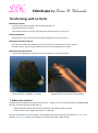
Terraforming with no limits
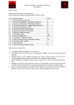
EdenScape Creator
Create terrains from a height maps created external to SL.
Copy-paste terrains in-world.
Save backup of the sim terrain, and restore the whole parcel or any part of it.
EdenScape Backup
Save backup of the sim terrain, and restore the whole parcel or any part of it.
EdenScape terraform Stencil
Area tool to terraform the whole parcel or any area set by coordinates or corner markers.
Smooth surfaces, flat leveling, raise/lower the area preserving the terrain shape.
EdenScape terraform Brush
Free tool for applying any terraform action in step-wise or continuous mode.
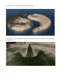
Spiral mountain, 100x100m, 71 m high
Island made from the avatar shape, 64x30m
1. What is the tool for?
Scripted terrain modification has never been as easy… maybe it’s not so easy but certainly manageable with
this tool. The basic functions of the tool are
o Take backup and restore the terrain from backup, copy-paste terrains in-world
o Create terrain from a height map saved on a notecard
Rez the tool and left-click it for the menu. In the following, the menu buttons are shown in blue color. For
example, Apply stencil means you should press a button with label “Apply stencil”.
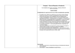
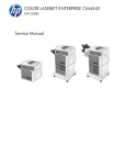
Left: Yin-Yang islands clipped from a public domain image. Right: 70 m high ski jump hill, with perfectly
smooth spline contour, giving a great jump for any physical object or sledge.
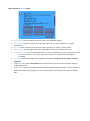
Main menu
Rez the tool EdenScape on the ground and left-click to access the menu.
The tool supports two modes, Notecard and Backup. Press the button Set mode to choose the mode.
•
•
Notecard : terrain patch (called stencil in the
following) is read from a notecard
Backup : save and restore a parcel or part of a
parcel, and copy-paste terrains in-world
The light version EdenScape Backup has only the backup
mode, for saving and restoring parcel terrain. For users
of the EdenScape Backup the following chapters are
relevant: Chapter 2. Restoring terrain from backup; in
Chapter 3 sections SafeMode and Stencil corners, and
Chapter 4 for additional information (which is definitely
not required reading for using the tool).
Emergency stop button
The tool comes with an object ‘EdenScape stop button’ that can be used to stop the terraforming tool while
it is processing. Attach it as HUD before starting the tool. Clicking the upper red button sends the
EdenScape tool a command that resets the main script and immediately stops any processing. . You can
also shout command /911911 stop for emergency stop. Clicking the lower button requests the tool to
stop softly, after the current row of the stencil is processed.
In typical use the stop button should not be needed. The button is provided for additional safety when
processing large areas, to stop the tool if the settings appear to be clearly wrong and risk messing up
existing terrain. Note that the backup facility can be used to save the terrain before starting the
terraforming and restoring the terrain if the result is not as desired.
It is advised to always check the processed area, using Show corners button, before starting the
terraforming.
2. Restoring terrain from backup
First we present some example scenarios for restoring the terrain from backup. A complete list of buttons
in the backup menu follows. The tool has modify permissions to allow renaming it to easily find your
backups from inventory.
Example scenarios
• You have rented or bought a parcel where you have terraform rights. You don't have terraform rigths
in neighboring parcels (that is, you can safely apply terraform operations outside your parcel without
adverse effects)
1. Save backup
o Rez the tool on your parcel and press Save backup
2. Restore the parcel
o Rez the tool on your parcel
o To check the backup, press Backup info
o Set mode > Backup
o Uncheck SafeMode
o Whole parcel
o Apply stencil
If you have terraform rights on neighboring parcels, check SaveMode .
• Restore 15 x 25 m area from the backup, with the tool at the SW corner of the area
o Set mode > Backup
o Set area , type 15 25 and press Send
o Apply stencil
• Interactively select the area to restore from backup
o Set mode > Backup
o Show corners, right click/edit and move the corners to set the area
o (Hide corners)
o Apply stencil
• Copy-paste 100 x 150 m area from sim A at 13, 180 to sim B starting at 30,80
o Go to sim A and rez the tool and press Save backup
o Go to sim B and rez the tool
o Set mode > Backup
o Source SW corner, type 13 180 and press Send
o Set area , type 100 150 and press Send
o Set SW corner, type 30 80 and press Send
o (To check the area, press Show corners and Hide corners)
o Apply stencil
• Interactively select the positions to copy-paste an area from sim A to sim B
o Go to sim A, rez the tool and press Save backup
o Set mode > Backup
o Show corners, click any corner to switch the corner markers to resize mode, (blue corners),
and edit/move the corners to set the position
o Source SW corner, type the current SW corner coordinates, and Send
o Go to sim B and rez the tool
o Set mode > Backup
o Show corners, edit/move the corners in move mode (pink corners) to the desired location
o Apply stencil
Menu buttons in Backup mode
•
•
•
•
•
•
•
•
Save backup: saves the whole sim terrain map in the clipboard memory
Set SW corner: opens a textbox to set the South-West corner of the target area, in region
coordinates
Set area: opens a textbox to set the size of the target area, as <Xsize> <Ysize> meters
Whole parcel: sets the target area as the bounding box of the parcel where the tool is
Source SW corner : sets the South-West corner in the stored backup, for copy-pasting terrain from
one area to another. The source may be in another sim, in which case the tool gives
a warning.
Save PGM : prints the defined area in PGM format (see 4.4. Using the terrain maps in external
programs)
SafeMode : see section Safe mode below. Uncheck this if you do not have terraform rights in
neighboring parcels.
Backup info: requests the backup headers from the clipboard memory scripts. You can use this to
update the backup info settings at any time. Resetting the main script will not clear the backup
data.
3. Creating terrain from a height map
The tool supports creating terrain maps outside of SL, and recreating the terrain in SL. The terrain maps are
stored as ASCII PGM image files, supported by many image processing software tools. See section 4.2. PGM
file format for more info on creating and converting the terrain maps.
To start creating the terrain, press Set mode > Notecard , which opens a menu to choose the notecard.
After reading the notecard, the tool opens a menu showing information of the loaded stencil and settings
that determine how the stencil is applied. When you are satisfied with the settings, press Apply stencil to
start terraforming. Every terraforming action has a confirmation menu to avoid accidentally starting it.
Settings of the stencil:
o Set SW corner : sets the South-West corner of the area where the stencil is applied. The default
position is the position of the tool when loading the notecard, or it can be set in the notecard (see
section 4.3. PGM file format) . The SW corner of the stencil is not changed if you move the tool.
o Set level : sets the ground level of minimum height in the stencil. The default value can be set in the
notecard,with a line “# minground <level>”. The submenu has the following options:
o Ground SW : sets the level to the ground height at the SW corner
o Tool Z : sets the level to the tool position z-coordinate
o Type level: opens a textbox to type in the level
o Set range : sets the height range. The default value may be set in the notecard, by comment lines
“#minground <level>” and “maxground <level> “. For example, the notecard may have a setting “#
minground 25” and “# maxground 40”, giving the basic level 25 and range 15 as the default apply
settings. To create the terrain at level 20 with range 10, use Set level / Type level , type “20” and Set
range, type “10”.
o SafeMode : see section Safe mode below.
o Show corners : rezzes corner markers to set the position of the area. See section Stencil corners.
o Apply stencil : starts the terraforming, with a confirmation menu to avoid accidental button presses.
o Undo stencil : restores the stencil area from the backup. The undo is not perfect, see section Safe
mode for artifacts on the area boundaries. The backup is not automatically saved prior to applying a
stencil from notecard, use Save backup to save it. You can also restore the area by using the backup
mode, see section 2. Restoring areas from backup.
o Alpha : use alpha mask, see section 4.2. Alpha mask. Values 0 in the notecard are not rendered.
Some old viewers do not support the textbox UI component. (LL viewers prior to 2.4 and some TPV's.) The
unsupported viewers will display a dialog menu with a single button "!!llTextBox!!". To support users on
those viewers, when launching a textbox the tool shows instructions in chat how to input the text via chat
command.
The tool does not support rescaling or rotation of the terrain maps in notecards. If you need to rotate or
rescale the terrain maps, save the notecard in text file, load it in any image manipulation program (such as
IrfanView, see section 4.4. Using the terrain maps in external programs) , apply the transformations and
save as ASCII PGM file, and copy it on a notecard and drop in the tool.
Safe mode
The tool has a setting SafeMode that controls how the borders of the processed area are handled, and
whether the tool is allowed to terraform outside the parcel. See section 4.1. Terraforming explained for
introduction to the way the tool works. SafeMode options are:
• SafeMode OFF :
o Simple rule: use this in restoring backup if you do not have terraform rights in neighboring
parcels
o Description: with this setting the full stencil area is processed, producing perfect result
inside the area, but leaving artifacts on the North and East borders outside of the area.
Note that when restoring the whole parcel from backup, or any area at the parcel
boundary, this causes terraforming in the adjacent parcel, in case you have terraform rights
for the other parcel. If you do not have terraform rights on adjacent parcels to North and
East, this setting is recommended for restoring the parcel.
• SafeMode ON :
o Simple rule: use this if the area you process touches other parcels and you have terraform
rights in those parcels
o Description: with this setting all processing is strictly inside the area and only in the parcel
where the South-West corner is, thus not affecting existing terrain out of the area. This is
useful if you create a patch of terrain very near to terrain you have to preserve. This is
useful also if you have terraform rights on the neighboring parcel and the area is less than 2
meters from the North and East boundaries.
Stencil corners
The position of the stencil, and the size for the backup restore, can be adjusted interactively from the
button Show corners, which rezzes pink corner markers. The corners can be moved by normal editing tools
(right click / edit, drag the red, blue or green arrows). The corners snap to the terrain grid automatically
after they are moved.
In Backup mode the size of the area can be changed by clicking any of the corners (r-click/touch if the prim
is in edit). The resize mode is indicated by blue color. Clicking Hide corners the corners are deleted and the
menu is updated with the current values. (The values are sent to the tool immediately after the corner is
moved but the dialog menu cannot show the update until it is refreshed; you can also remove the menu by
‘Ignore’ and click the tool for updated menu.).
If a corner moves to a different parcel it changes the color to bright red. Use SafeMode setting to choose
whether the terrain in other parcels is processed.
If the corners are left accidentally visible after you derez the tool, you can remove them by shouting
/8 stencil|die
Pink corners: move the stencil
Blue corners: resize the stencil
4. Technical information
This looks boring. You don’t need to read it, unless you want to create terrains that fit tightly to existing
terrains. The terraforming brush available in SL is rather clumsy, and causes side-effects – think of painting
one centimeter details with three centimeter brush; after painting one spot you have to paint over the
extra paint in the brush area, and this is how the terraform brush works also. See also the SafeMode above
for handling those side-effects.
4.1. Terraforming explained
The terrain in SL is defined in 1 m x 1 m grid, but the function modifying the terrain (llModifyLand) affects
minimum of 2 m x 2 m area ( 3 x 3 grid points), requiring carefully planned order of the terrain brush
actions to obtain the 1 m resolution. The tool uses a very simple terraforming pattern that has caveats:
getting the terrain exactly correct inside the processed area the tool needs to process 2 m wide zones
outside the North and East borders. Respectively, restricting the processing strictly inside the area leaves 2
m wide zones with artifacts inside the North and East borders. (While it is possible to build any terrain with
processing only inside the area, finding out the appropriate sequence of terraform actions requires solving
a large set of simultaneous equations (for a 30 x 40 m area it requires inverting a matrix of size 1200 x
1200), or alternatively a lengthy iterative optimization, which are prohibitively costly in terms of memory
and CPU in lsl, unless someone comes up with really good heuristics for the optimization.)
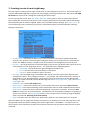
To demonstrate the way the terraforming is done by the tool, consider following stencil:
26
22
18
14
10
27
23
19
15
11
28
24
20
16
12
29
25
21
17
13
Let us assume flat ground with height 1 and apply the stencil with the SW-corner at (3,3). The resulting
terrain is shown below, with the stencil area shown on red.
1
1
1
1
1
1
1
1
1
1
1
1
1
1
1
1
1
1
1
1
1
1
1
1
1
1
1
1
1
1
1
1
1
1
1
1
1
1
1
1
1
1
1
1
1
1
1
1
1
1
26
26
26
22
18
14
10
1
1
1
1
1
1
1
1
27
27
27
23
19
15
11
1
1
1
1
1
1
1
1
28
28
28
24
20
16
12
1
1
1
1
1
1
1
1
29
29
29
25
21
17
13
1
1
1
1
1
1
1
1
29
29
29
25
21
17
13
1
1
1
1
1
1
1
1
29
29
29
25
21
17
13
1
1
1
1
1
1
1
1
1
1
1
1
1
1
1
1
1
1
1
1
1
1
1
1
1
1
1
1
1
1
1
1
1
1
1
1
1
1
1
1
1
1
1
1
1
1
1
1
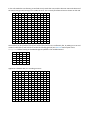
In the safe mode the terraforming is confined strictly inside the area, and the last two rows and columns of
the stencil are ignored, leaving errors inside the area. The correctly terraformed area is shown on dark red.
1
1
1
1
1
1
1
1
1
1
1
1
1
1
1
1
1
1
1
1
1
1
1
1
1
1
1
1
1
1
1
1
1
1
1
1
1
1
1
1
1
1
1
1
1
1
1
1
1
1
1
1
18
18
18
14
10
1
1
1
1
1
1
1
1
1
1
19
19
19
15
11
1
1
1
1
1
1
1
1
1
1
19
19
19
15
11
1
1
1
1
1
1
1
1
1
1
19
19
19
15
11
1
1
1
1
1
1
1
1
1
1
1
1
1
1
1
1
1
1
1
1
1
1
1
1
1
1
1
1
1
1
1
1
1
1
1
1
1
1
1
1
1
1
1
1
1
1
1
1
1
1
1
1
1
1
1
1
1
1
1
1
1
1
1
1
1
1
1
1
1
1
1
1
1
1
1
1
1
1
The artifacts can be avoided if the terrain around the stencil area is sufficiently flat, by adding one row and
column to the stencil, with values set to the surrounding ground. (See Set level menu option and #
minground default setting in the PGM image file.) Below is the modified stencil.
1
26
22
18
14
10
1
27
23
19
15
11
1
28
24
20
16
12
1
29
25
21
17
13
1
1
1
1
1
1
Applied in SafeMode OFF, the resulting terrain is:
1
1
1
1
1
1
1
1
1
1
1
1
1
1
1
1
1
1
1
1
1
1
1
1
1
1
1
1
1
1
1
1
1
1
1
1
1
1
1
1
1
1
1
1
1
1
1
1
1
1
1
1
26
22
18
14
10
1
1
1
1
1
1
1
1
1
1
27
23
19
15
11
1
1
1
1
1
1
1
1
1
1
28
24
20
16
12
1
1
1
1
1
1
1
1
1
1
29
25
21
17
13
1
1
1
1
1
1
1
1
1
1
1
1
1
1
1
1
1
1
1
1
1
1
1
1
1
1
1
1
1
1
1
1
1
1
1
1
1
1
1
1
1
1
1
1
1
1
1
1
1
1
1
1
1
1
1
1
1
1
1
1
1
1
1
1
1
1
1
1
1
1
1
1
1
1
1
1
1
1
The stencil area is marked as red and the artifacts produced by the tool outside the area as blue.
Alternatively, the stencil may be padded by 3 columns and rows and the tool applied with the Safe mode
ON. This helps to see the exact area affected by the tool, using the Show corners function.
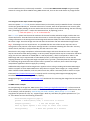
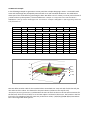
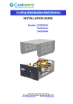
Other issues
Ragged diagonal edges. The terrain in SL is defined in a grid with 1 m resolution, and the ground is
interpolated linearly between the grid points, with every square meter split to two triangles diagonally in
direction SW to NE. The left figure below shows the triangles in an example; the other figures show the
effect on how ground is rendered. Diagonal structures in SW - NE are preserved but diagonal structures in
NW - SE are not (see the middle figure).
10 20
20 10
20 10
10 20
10 20
20 10
20
20
15
15
10
2
10
2
1.5
y
1
1
1.5
x
2
1.5
y
1
1
1.5
x
Left: example of 1 m x 1 m terrain patch, showing the triangles used in interpolation in viewer and llGround()
Middle: resulting terrain when the high ridge is in NW-SE direction
Right: resulting terrain when the high ridge is in SW-NE direction
Actual terrain example.
On the left side, diagonal ridge in NW - SE direction
On the right side, diagonal ridge in SW- NE direction
2
Flat areas showing rough. The SL viewer adds noise on the ground during rendering, apparently to simulate
natural terrains. Near steep edges the noise is added 4 to 8 m from the edge. To avoid this, smoothen the
corners of steep edges. The figure below shows the effect; the ground as returned by llGround() is perfectly
flat in the image.
Noise added by the viewer in rendering the terrain. The ground
around the high area is perfectly flat.
SL BUGS in terraforming: sometimes the ground is rendered wrong after terraform operations,
see JIRA https://jira.secondlife.com/browse/VWR-24882 . This bug affects the borders of the areas
processed by the tool; when the bug is expressed it looks like the tool has not processed the last meter
near the edges, but checking the ground by llGround() function shows the desired result, and the rendered
ground is incongruent with the result of llGround() function. The incidence rate of the bug is not known.
4.2. Alpha Mask
For creating non-rectangular terrain patches over existing terrain, without need to copy the existing terrain
into the stencil, the stencil specification has a simple optional alpha mask: when alpha mask is used, the
value 0 in the notecard defines position that is not terraformed. Alpha mask can be switched ON or OFF by
the Alpha menu button, and the default value can be set ON in the PGM-file notecard with comment line
# alpha.
When alpha mask is used, the exact value set to the base level is not possible, the lowest value terraformed
is base level + 1/<Maxval>*range. For example, if the stencil terrain range is 100 m and the base level is 20
m, and <Maxval> is 1000, the notecard pixel values map to following ground heights.
NC
0
1
2
1000
Heigth
20
20.1
20.2
120
Not terraformed with alpha mask ON
Lowest ground height terraformed
The areas masked as alpha have the same boundary artifact issue as described above for the stencil
boundaries. Every non-alpha pixel causes 2 m x 2 m area to the East and North affected, hence the alpha is
usable only for masking out larger areas, not individual positions.
The figure below demonstrates the effect. We add a round patch of terrain and try to avoid touching the
existing terrain around the patch by alpha mask. The red circles show the pixels with non-alpha values
defining the target terrain in the 32 x 32 stencil. The green and blue pixels are alpha in the notecard. Due to
the terraforming algorithm the blue positions are terraformed as side effect of applying the terrain brush in
the red positions. Consequently, the stencil needs to have suitable non-alpha values on borders next to
alpha values to the North and East. For example, if the stencil below has a constant value on the border of
the non-alpha area (red), the blue area will be filled with that value, and setting the value correspond to
the surrounding ground, the new patch blends into the terrain.
30
25
20
15
non-alpha, terraformed
alpha, artefact terraformed
alpha, not terraformed
10
5
0
0
5
10
15
20
25
30
4.3. PGM file format
The terrain stencils are stored as PGM image files. If the tool you use does not support ascii PGM-format,
Irfan view (http://www.irfanview.com/) is handy free program for converting between image formats. To
save the file in Irfan view, choose File/Save As, and Save as type: PGM - Portable
Graymap, and set the ascii option in the pop-up window: Save options: Ascii encoding.
The ascii PGM image consists of the following :
(See http://netpbm.sourceforge.net/doc/pgm.html)
1. A "magic number" for identifying the file type. The tool uses ASCII PGM files with tag "P2"
2. Whitespace (blanks, TABs, CRs, LFs).
3. A width, formatted as ASCII characters in decimal.
4. Whitespace.
5. A height, again in ASCII decimal.
6. Whitespace.
7. The maximum gray value (Maxval), again in ASCII decimal. Must be less than 65536, and more than zero.
8. Newline character
9. A raster of Height rows, in order from top to bottom. Each row consists of Width gray values, in order
from left to right. Each gray value is a number from 0 through Maxval, with 0 being black and Maxval being
white. In the tool the rows run from West to East and the columns from South to North. As images typically
have origin in top left, displaying the terrain map as an image with North up, you need to flip the image
vertically.
Lines starting with "#" are comments, and can appear anywhere in the file. The tool recognizes also "[" as a
comment tag, to allow copy-pasting the tool output directly on a notecard.
The tool recognizes the following comment lines as terraform prameter default values:
# minground <float_value> : specifies the default ground level of pixel value 0
# maxground <float_value> : specifies the default ground level of pixel value <Maxval>
# Parcel SW corner: <integer_x> <integer_y> : specifies the default SW-corner of the stencil,
in region coordinates
# alpha : turns on alpha mask, with positions with pixel value 0 not terraformed
Example of the stencil PGM file:
P2
# minground
# maxground
# Parcel SW
# alpha
104 104
999
0 0 0 0 0 0
20 25 31 36
2 0 0 0 0 0
15.000000
71.000000
corner: 103 77
0 0 0 0 0 0 0 0 0 0 0 0 0 0 0 0 0 0 0 0 0 0 0 0 0 0 0 2 3 5 7 11 15
41 46 51 53 53 53 53 53 53 53 53 53 51 46 41 36 31 25 20 15 11 7 5 3
0 0 0 0 0 0 0 0 0 0 0 0 0 0 0 0 0 0 0 0 0 0 0 0 0 0 0 0 0 0 0
...
To use the file with the tool, open the file in any text editor, copy the contents on a notecard, and drop the
notecard into the tool. Note the notecard limits: maximum line length is 255 characters, and maximum
notecard size is 64K. Large files that don't fit on one notecard can be split, with continuation parts named
as <main notecard>_Part2, <main notecard>_Part3, etc. The files can be clipped at any row, but not inside a
row. For example, to create a full sim terrain map (64K positions) with <Maxval> 999, each position
requires roughly 4 bytes and the whole map requires 4 notecards, for example,
mysim
mysim_Part2
mysim_Part3
mysim_Part4
The terrain values are stored internally as 15-bit integers, independent of the <Maxval> value in the PGM
file. Using larger <Maxval> gives higher vertical resolution, and produces larger image files. As an example,
<Maxval> value 1000 with 10 m range (i.e., <maxground> - <minground>) gives resolution 10 mm for the
height mapping.
Internally the height maps are stored as 15-bit integers, with the actual height as <value>/128 meters,
yielding maximum vertical resolution of 1/128 m, or 8 mm.
Typical image manipulation programs support 8-bit images, corresponding to <Maxval> of 255. The
maximum terrain height with terraforming is 255 but in many sims it is limited to around 100 m. The 8-bit
depth allows 25 cm height resolution for terrains with range of 64 m, which should be often sufficient. For
higher resolution it is possible to use 16-bit images (with e.g. Photoshop), but tools to convert the images
to ascii PGM format may not be easily accessible. . In section 4.5 GNU Octave example we give example
routine for saving the 16-bit PGM file using GNU Octave tool, that can also read almost any image format.
4.4. Using the terrain maps in external programs
Use menu option Print PGM to print the selected area (or the whole parcel) in PGM-file format. The output
can be copy-pasted directly on notecard to be used as a stencil, with all the parameters set correctly (SW
corner, levels, alpha). Editing the terrain with external tools requires some manual editing: the lines starting
with "[<timetag>] tool name: " need to be commented out, by replacing [ with #.
!! Find and replace "[" to "#" in the whole file
The Print PGM option lists the vertical resolution of the area for 8-bit and 16-bit images, and lets the user
choose the format. The 8-bit format rescales the terrain to use the full range of 256 values, and stores the
scaling information in the # minground and # maxground comment fileds; thus the resolution depends on
the terrain range. The 16-bit image uses the tool internal resolution of 8 mm and absolute height levels.
Bugs: all messages in SL are asynchronous. It is possible that the rows of the terrain map come out in
wrong order in the printout. Each output message contains a comment indicating the row index. You may
need to check, manually or programmatically, that the rows are in order.
Note that the way image manipulation software handle images with more than 8 bits varies. The image
may be converted to 8 bits during loading. In 16-bit systems the pixel values may be converted to full 16 bit
range; the tool sets <Maxval> to 32768 (256 m * 128 steps/meter), which corresponds to 'white' in the
PGM image and may be represented as value 65535 (2^16-1) in the image software. In that case the
mapping between the actual ground height and pixel value is ground = pixelvalue/256. The default formula
for calculating the ground level from the pixel value is printed as a comment, that is valid if the image
manipulation application does not apply any rescaling.
Adobe Photoshop supports 16-bit images but it appears to have a bug in reading 16-bit ASCII PGM images
and has no option to write ASCII PGM format. Gimp does not support 16-bit images yet. Gimp produces
rather inefficient ASCII PGM files, with one pixel on each line, which is extremely slow to read in SL scripts.
IrfanView (http://www.irfanview.com/) is a handy tool for converting 8-bit images and applying basic
transformations, such as rescaling, rotation, flipping.
Netpgm package (http://netpbm.sourceforge.net/) should work for converting the images but has not been
tested.
4.5 GNU Octave example
For manipulating the image files, GNU Octave (http://www.gnu.org/software/octave/) is a free numerical
math software tool, and has been tested to work. You can use it for converting to other 16-bit formats also.
As an example, save the parcel by Save backup, Set mode > Backup, Whole parcel, Print PGM and
copy/paste the printout in a file, say ‘myparcel.pgm’. With any text editor, do global replacement of ‘[‘ to
‘#’. Start Octave and use the following commands
data=imread('myparcel.pgm');
ground = double(data)/128; % scale back to meters
imagesc(ground);
% see the height map
axis xy equal square % set origo in lower left corner
surf(ground);
% show the ground as a surface
% save as 16-bit png file that works in PS
imwrite(data,'myparcel.png','png');
GNU Octave is very handy tool with rich scripting language for creating the terrains. For an arbitrary
example, you have a nice mountain but it’s too high, and we flatten the height range above the sea level by
factor of two, but preserve the sea depth.
waterlevel=20;
data=imread('myparcel.pgm');
ground = double(data)/128; % scale back to meters
J = find(ground>waterlevel);
ground(J) = (ground(J)-waterlevel)/2 + waterlevel;
% save with the same scaling it was,
% the routine write_pgm is given below
write_pgm(ground*128, 'after_iceage.pgm',0,256,[],[], 32767);
% we can also scale to 3-digit integer to fit larger area in one
% file and set the min/max ground. (With about 4 bytes per pixel
% one file (65000 B) can fit ~ 17 000 m2, or 100 x 170 area)
gmin=min(ground(:));
gmax=max(ground(:));
img=round((ground-gmin)/(gmax-gmin)*1000);
write_pgm(img,'after_iceage.pgm',gmin,gmax);
Note: edit and copy/paste the comment line setting the parcel SW corner from the original file to the new
file, or set Full Parcel in the terraform tool
# Parcel SW corner:
Below is a Matlab/Octave function to save the data as ASCII PGM file compatible with the terraform tool.
function write_pgm(m,fileName,minground,maxground, comments, maxFileSize,maxval)
% write_pgm(m,fileName,minground,maxground, comments, maxFileSize,maxval)
% Writes data as ASCII PGM file compatible with EdenScape terraform tool
%
m - image data
%
fileName - output file
% Optional arguments
%
minground - default ground level of pixel value 0
%
maxground - default ground level of pixel value maxval
%
comments - string or cell array of additional comments,
%
e.g. {'comment1','comment2'}
%
maxFileSize - maximum output file size, default 65000 bytes
%
maxval
- maxval used in scaling the data, default is
% Empty values are replaced by defaults, f.ex.
%
write_pgm(m,'island.pgm',[],[],'alpha');
if ~exist('minground','var') || isempty(minground), minground=0; end
if ~exist('maxground','var') || isempty(maxground), maxground=255; end
% default max file size is the SL notecard max size
if ~exist('maxFileSize','var') || isempty(maxFileSize), maxFileSize=65000; end
if ~exist('comments','var') comments={}; end
if ~iscell(comments) comments = { comments };end
if ~exist('maxval','var') || isempty(maxval), maxval=max(m(:)); end
partNumber=1;
file=fileName;
f=fopen(file,'w');
fprintf(f,'P2\n# minground %f\n# maxground %f\n',minground,maxground);
for k=1:length(comments),
fprintf(f,'# %s\n',comments{k});
end
fprintf(f,'%d %d\n%d\n',size(m,2),size(m,1),maxval);
for k=1:size(m,1),
s='';
for j=1:size(m,2),
t=sprintf('%d ',m(k,j));
% check the current file size, slow but proof
D=dir(file);
if D.bytes + length(t) + length(s) > maxFileSize,
% need another part
[pathstr, basename, ext] = fileparts(fileName);
fclose(f);
partNumber=partNumber+1;
newfile=fullfile(pathstr,sprintf('%s_Part_%d%s',basename,partNumber,ext));
f=fopen(newfile,'w');
disp(sprintf('File %s full, opened new file %s',file,newfile));
file=newfile;
end
% check for max NC line length
if length(s)+length(t)>255,
s(end)='';
fprintf(f,'%s\n',s);
s='';
end
s = [s t];
end
if length(s)>0, s(end)=''; fprintf(f,'%s\n',s); end
end
fclose(f);
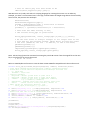
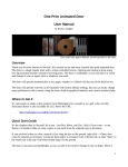
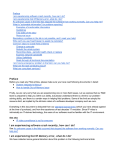
4.6 MS Excel example
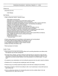
In the following example we generate a terrain patch like a droplet dropping in water: a sinusoidal radial
wave with wavelength 8 m, damped by Gaussian bell curve with standard deviation 4. The table below
shows part of the excel table for generating the data. We define row of x values (-10 to 10) and a column of
y values and set up the equation; the sinusoidal wave is COS( R *2*3.14/L) where the radial variable R is
SQRT(B$2^2 + $A5^2), and the wavelength L is 8. The Gaussian envelope is EXP(-(B$2^2 + $A5^2)/(2*S^2)) where the
s.t.d parameter is 4.
x
y
-10
-9
-8
-7
-6
-5
-4
-3
-0.02
0.01
0.06
0.13
0.16
0.09
-0.1
-0.32
-0.5
-0.59
-0.01
0.02
0.09
0.16
0.13
-0.05
-0.32
-0.56
-0.63
-0.58
=COS(SQRT(B$2^2 + $A5^2)*2*3.14/8)*EXP(-(B$2^2 + $A5^2)/(2*4^2))
-10
-9
-8
-7
-6
-5
-4
-3
-2
-1
0
-0
-0
-0.01
-0.01
-0.02
-0.02
-0.01
-0.01
-0
-0
-0.01
-0.01
-0.02
-0.02
-0.01
0.01
0.02
0.04
0.05
-0
-0.01
-0.02
-0.01
0
0.03
0.06
0.09
0.12
0.13
-0.01
-0.02
-0.01
0
0.04
0.09
0.13
0.16
0.16
0.16
-0.01
-0.02
0
0.04
0.1
0.15
0.16
0.13
0.07
0.02
-0.02
-0.01
0.03
0.09
0.15
0.16
0.09
-0.05
-0.19
-0.29
1
0,5
0
-0,5
1
3
5
7
9 11 13
15 17 19
21
0,5-1
Series19
Series13 0-0,5
Series7
-0,5-0
Series1
-1--0,5
-1
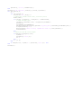
Next we define another table for the rounded values normalized to 0...255, with aid of cells that tally the
min and max of the values. The formula for the pixel values is (relative to the top left cell)
=ROUND(255*(B5-$F$27)/($F$28-$F$27);0) whereF28 is the max cell and F27 the min cell. We add a comment for
the flat level, that is the zero value, so we can later adjust it to blend in the terrain. The formula in the flat
level cell is just mapping of 0 by the same way as the other values; =(0-$F$27)/($F$28-$F$27)*E31 where
E31 is the maxground value typed in.
P2
# maxground
# flat level
21
21
255
99
99
99
98
98
97
97
97
97
97
96
98
97 100
97 103
98 105
99 107
99 108
99 107
98 105
97 103
97 100
96
98
97
97
97
97
98
97
99
98
99
99
10
3.88
98
97
97
97
99
103
108
113
117
119
120
119
117
113
108
103
99
97
97
97
98
97
97
97
100
105
113
119
123
124
123
123
123
124
123
119
113
105
100
97
97
97
97
97
99
105
114
122
124
119
110
102
99
102
110
119
124
122
114
105
99
97
97
96
98
103
113
122
123
112
92
70
54
48
54
70
92
112
123
122
113
103
98
96
97
100
108
119
124
112
84
48
21
8
4
8
21
48
84
112
124
119
108
100
97
97
103
113
123
119
92
48
12
0
9
16
9
0
12
48
92
119
123
113
103
97
98
105
117
124
110
70
21
0
25
74
99
74
25
0
21
70
110
124
117
105
98
99
107
119
123
102
54
8
9
74
164
206
164
74
9
8
54
102
123
119
107
99
99
108
120
123
99
48
4
16
99
206
255
206
99
16
4
48
99
123
120
108
99
99
107
119
123
102
54
8
9
74
164
206
164
74
9
8
54
102
123
119
107
99
98
105
117
124
110
70
21
0
25
74
99
74
25
0
21
70
110
124
117
105
98
97
103
113
123
119
92
48
12
0
9
16
9
0
12
48
92
119
123
113
103
97
97
100
108
119
124
112
84
48
21
8
4
8
21
48
84
112
124
119
108
100
97
96
98
103
113
122
123
112
92
70
54
48
54
70
92
112
123
122
113
103
98
96
97
97
99
105
114
122
124
119
110
102
99
102
110
119
124
122
114
105
99
97
97
97
97
97
100
105
113
119
123
124
123
123
123
124
123
119
113
105
100
97
97
97
98
97
97
97
99
103
108
113
117
119
120
119
117
113
108
103
99
97
97
97
98
99
98
97
97
97
98
100
103
105
107
108
107
105
103
100
98
97
97
97
98
99
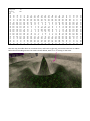
Next we copy the table above on a notecard in SL, and load it in the tool, and set the base level as 3.88 m
below the surrounding terrain. The result is shown below, with Linda B sitting on the wave.
99
99
98
97
97
96
97
97
98
99
99
99
98
97
97
96
97
97
98
99
99
LH
B
EdenScape by Linda
B Helendale
Description of the terrain notecards included in EdenScape Creator purchase
SpiralMountain 100x100 : 100 x 100 m spiral mountain with four paths leading to the top.
Fback 64x32 : 64 x 32 m island with shape from the SL female avatar
Ffront 64x30 : 64 x 30 island with shape from the SL female avatar
Ftop 32x32 : 32 x 32 hill made from SL female avatar torso
Fbum 32x32 : 32 x 32 hill made from SL female avatar lower body
Jin-Jang 57x64 : 57 x 64 m island made from a jin-jang image
excelExample : 21 x 21 m droplet wave shape; the user manual shows how to make this terrain map in MS
Excel spreadsheet
Maze 32x32 : 32 x 32 m maze generated with a maze script; any maze raster image can be used to make a
terrain maze