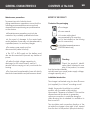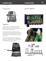
1
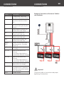
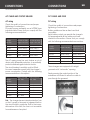
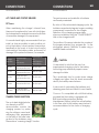
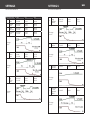
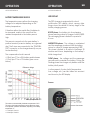
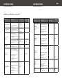
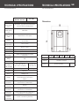
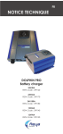
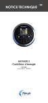
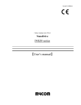
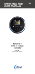
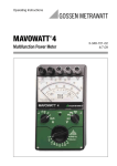
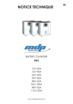
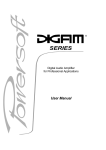
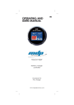
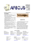
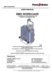
OPERATING AND
USERS MANUAL
DOLPHIN PRO
Battery charger
24V40A
REYA Code : 399160
24V60A
REYA Code : 399170
24V100A
REYA Code : 399180
12V60A
REYA Code : 399140
12V90A
REYA Code : 399150
UK
SAFETY PRECAUTIONS
SAFETY PRECAUTIONS
NOT-DOLPROREYA-03
NOT-DOLPROREYA-03
TO PREVENT ANY RISK
OF ELECTRIC SHOCK OR FIRE,
READ THIS MANUAL CAREFULLY
BEFORE INSTALLING THE EQUIPMENT.
In the event of any problems or misunderstandings, please contact REYA.
This equipment is not designed for use by people
(including children) with diminished physical, sensorial or mental capacities, or people without experience or knowledge of such equipment, unless
they have received prior instruction in the use of
the equipment from a person responsible for their
safety or are under the supervision of such a person. Ensure that children are supervised in order to
prevent them playing with the device.
This equipment contains components that may
cause electric arcs or sparks, when connecting
cables, for example.
To prevent any risk of fire or
explosion, do not install this equipment close to
flammable materials, liquids or gases.
Installation precautions.
UK
4This device must not be exposed to running water, water spray and dust of any kind.
4We recommend securing the device in a vertical position, with the cable outlet pointing
downwards.
4You are formally prohibited from making
mechanical alterations to the housing, including
making additional holes, for example.
4Under no circumstances should this device be
seen as a toy.
It should therefore, quite clearly, not be left in
the hands of a child.
Connection precautions.
To prevent any risk of electric shock or
irreversible damage to the equipment, you
should comply strictly with the following
recommendations.
4The installation to which this device is
connected must comply with the applicable
regulations.
To prevent any risk of irreversible damage
to the equipment, ensure that you
comply scrupulously with the following
recommendations.
4This device is designed to be connected to
220-240V 50Hz or 100-120V 60Hz single phase
circuits. 115V / 230V selection is automatic.
220-240V only for 24V100A version.
4This device must not be installed close to
a heat source.
4The mains power line must feature a cut-off
device with differential protection, to protect
individuals against electric shocks. Refer to the
device’s electricity consumption characteristics
to select the size and type of circuit breaker.
4It must not be installed in an airtight or
badly-ventilated compartment.
4The ventilation inlets must not be obstructed.
4Clearance of at least 10 cm must be allowed
around the housing to guarantee adequate
convection.
SAFETY PRECAUTIONS
NOT-DOLPROREYA-03
4Prior to commencing connection, the mains cable gland in the packaging must be assembled
and correctly attached to the housing (using the
nut provided), in the hole designed for this purpose.
4For safety reasons, the device’s EARTH terminal
(PE “Protective Earth” terminal), must be connected to the system’s physical earth (yellow & green
wire of the mains cable). Refer to the wiring diagram for more information.
4To prevent parasite heating, ensure that the cable cross-sections are correct and the connectors
are properly tightened.
IMPORTANT : This device is not protected against
battery polarity reversals. A battery connection
error automatically causes the battery fuses to
blow as well as irreversible damage to the circuit
board.
Activation precautions.
To prevent any risk of electric shock on activation or during operation, the protective cover
must be correctly positioned and screwed into
the housing.
This device complies with the applicable
regulations governing transmitted interference
and immunity from external disturbances (see
EMC paragraph in the Technical specifications
section).
When in operation, take particular care that
this device is not subjected to conducted or radiated interference at levels higher than the legal
limits otherwise malfunctions may occur (e.g.: device too close to a powerful transmitter).
SAFETY PRECAUTIONS
UK
NOT-DOLPROREYA-03
In other respects, this device transmits conducted
and radiated interference at levels that comply
with the applicable regulations. Ensure that other
sensitive equipment used in the vicinity is compatible with this device otherwise malfunctions
may occur.
Device serial number
The serial number appears on the grey or white
sticker on one side of the device. This number is
aligned vertically and comprises a first number
indicating the year of manufacture (e.g.: 12 for
2012), a letter indicating the month of manufacture (e.g.: C for the month of March), as well as
a 5-figure number that is the product’s individual
serial number.
Important
Note on the choice of charge curve
It is important to note that the use of an
inappropriate charging cycle for the battery
technology may extensively impair or even
damage the latter.
This is particularly true for cycles where the
charge voltages are higher than the levels
recommended by the battery manufacturers.
Example: A serious risk of overheating the
batteries and releasing gases that are harmful to
users’ health.
Curve no. 9 is compatible with a LiFeSo4
battery provided that the battery is equipped
with BMS-type battery protection (Battery
Management System) within the actual battery.
In this case, refer to the battery manufacturer’s
recommendations for the choice of charging
cycle.
GENERAL CHARACTERISTICS
CONTENTS of the BOX
NOT-DOLPROREYA-03
NOT-DOLPROREYA-03
Maintenance precautions
RECEIPT OF THE PRODUCT
To prevent any risk of electric shock
during maintenance operations, ensure that the
following recommendations are scrupulously
observed before performing any maintenance
on the device:
Contents of the packaging
4The charger.
4Its user manual.
4All maintenance operations must only be
carried out by a suitably qualified technician.
4Its mains cable gland
accompanied by its mounting
nut (to be installed on the housing
prior to connection).
4In the event of damage to the mains leads
and/or batteries, these may only be replaced by
a qualified person, to avoid any danger.
4The mains power supply must be
disconnected (cable or switch).
4 The -DC or -BAT supply on the battery must
also be disconnected to prevent any transfer of
power.
4To allow the high voltage capacitors to
discharge (on the circuit board), wait for 5
minutes before carrying out any work inside the
housing.
4The fuses must be replaced by fuses with strictly
identical characteristics and performance levels.
UK
4Its battery temperature sensor (24V100A version only)
Checking
Check the product’s identification label, attached to one
side of the product, to ensure
that the technical details
actually meet your needs (mains supply voltage,
charger capacity, etc.).
Installation introduction
The charger is attached using 4 x 4mm Ø screws
(not supplied), to a “robust” mounting or wall.
Ideally, the product should be in a vertical
position, with the cable outlet pointing
downwards. Clearance of at least 10 cm must be
allowed around the device to guarantee
optimum convection, in particular along the
sides allowing the air needed for ventilation to
flow in and out.
The circulation and convection direction of the
air inside the charger is from right to left, viewed
from the front of the product (see photo below).
CONNECTIONS
CONNECTIONS
NOT-DOLPROREYA-03
NOT-DOLPROREYA-03
Ventilation direction
DETAILS OF CONNECTIONS
warm
cool
CONNECTIONS
To gain access to the charger’s connections,
the front hatch must be removed. To do this,
simply unscrew the screw on the front hatch. The
hatch is removed by rotating it.
Prior to commencing connection, the mains
cable gland must be positioned and attached to
the housing in the hole designed for this purpose
(hole on the left, when viewed from the front of
the product).
The plastic nut supplied with the cable gland
allows it to be attached to the housing. This nut is
positioned on the inside of the housing. Ensure the
correct tightening torque is applied.
Mains cable gland
Front hatch
UK
CONNECTIONS
CONNECTIONS
NOT-DOLPROREYA-03
NOT-DOLPROREYA-03
Marking
Functionalities
L1
AC mains phase, 10mm2 max
(wire colour code: brown or black)
N
AC mains neutral, 10mm2 max
(wire colour code: blue, white or
red)
PE
AC mains earth, 10mm2 max
(wire colour code: green & yellow
or green)
-DC
battery negative (common), pin
M8 (wire colour code: black)
+DC1
Main battery positive, pin
M8 (wire colour code: red)
+DC2
Auxiliary battery 2 positive, pin
M8 (wire colour code: red)
+DC3
Auxiliary battery 3 positive, pin
M8 (wire colour code: red)
CHARGE
SELECT
Charge curve and battery charging mode selector, 10 positions
(from 0 to 9)
BATTERY FUSES
Battery protection fuses (on the
–DC supply)
EXT COM1
External communication bus
(CAN bus)
(for an external digital display or
communication between chargers)
EXT COM2
External communication bus
(CAN bus)
(for an external digital display or
communication between chargers)
INT COM
Communication bus for a digital
display built into the charger
TEMP SENSOR
Battery temperature sensor (2
non-polarised wires, no direction)
positioned on the positive terminal
of the main battery
REPLAY
Dry alarm contact
UK
Example of connection on the basis of 3 distinct
sets of batteries
Important
Check the quality of connections and proper
tightening of connections.
CONNECTIONS
NOT-DOLPROREYA-03
NOT-DOLPROREYA-03
AC CABLES AND CIRCUIT BREAKER
DC CABLES AND FUSES
AC wiring
DC wiring
Check the quality of connections and proper
tightening of connections.
For mains power, preferably use a HO7RNF-type
industrial cable. Ensure that you comply with the
following recommendations.
Charger
capacity
220-240V AC 50Hz
Length < 5m (16ft)
100-120V AC 60Hz
Length < 5m (16ft)
12V 60A
2.5mm2 / AWG13
4mm2 / AWG11
12V 90A
2.5mm2 / AWG13
4mm2 / AWG11
24V 40A
2.5mm2 / AWG13
4mm2 / AWG11
24V 60A
2.5mm2 / AWG13
4mm2 / AWG11
AC
24Vcircuit
100A breaker
4mm2
/ AWG11
6mm2 / AWG9
The AC mains power line must feature a cut-off
device with differential protection, to specifically
protect individuals against electric shocks.
The circuit breaker’s sensitivity must be 30mA.
Its current capacities comply with the charger’s
power consumption. Comply with the following
recommendations in this respect.
Mains power 220240V 50Hz
Mains power 100120V 60Hz
12V 60A
8A – 30mA
16A – 30mA
12V 90A
8A – 30mA
16A – 30mA
24V 40A
8A – 30mA
16A – 30mA
24V 60A
10A – 30mA
20A – 20mA
24V 100A
20A – 30mA
-
Charger
capacity
UK
CONNECTIONS
N.b. : The charger has an internal protection fuse
on the L1 supply, in the event of a general fault on
the circuit board in particular. Due to the irreversible nature of this fault, the fuse is not accessible
for maintenance of any kind.
Check the quality of connections and proper
tightening of connections.
Battery cables must be as direct and short
as possible.
Each battery output can provide the charger’s
full amperage and all the cables must have
identical cross-sections. Ensure that you comply
with the following recommended cross-sections.
Charger
capacity
Length < 2m (6ft)
Length between 3
and 5m (10 to 16ft)
12V 60A
25mm2 / AWG3
35mm2 / AWG2
12V 90A
35mm2 / AWG2
50mm2 / AWG0-1
24V 40A
16mm2 / AWG5
20mm2 / AWG4
24V 60A
25mm2 / AWG3
35mm2 / AWG2
24V 100A
35mm2 / AWG2
50mm2 / AWG0-1
These chargers are equipped with airtight
grommets with “automatic” opening.
Simply pressing the central section of the
membrane is sufficient to allow the cable to
pass through the grommet.
CONNECTIONS
CONNECTIONS
NOT-DOLPROREYA-03
NOT-DOLPROREYA-03
AC CABLES AND CIRCUIT BREAKER
The performance and usable life of batteries
are thereby maximised.
DC fuses
UK
When maintaining the charger’s internal fuses,
these must be replaced by fuses with strictly identical characteristics and performance levels. Risks
of irreversible damage to the equipment.
By virtue of fully automated charging cycles, the
batteries are protected against surges, providing
a permanent connection for the charger.
Selection of the charging program takes
place on installation using the “CHARGE SELECT”
dial on the charger board.
It is essential and highly recommended that you
install, as close as possible to each positive output on the battery, a fuse to protect connections,
specifically in the event of a short circuit and/or
overheating of the battery cables, as the result of
damage to the protective sleeves, for example.
The position of the arrow indicates the number of
the program selected (e.g.: program No. 1 in the
photograph above). Selection is made using a
small flat-head screwdriver.
Charger
capacity
Internal charger
fuse
(–DC supply)
External battery
fuse
(+BAT supply for
each battery)
12V 60A
3 x 25A 32V rapid
(mini automotive fuse)
80A 32V rapid
12V 90A
4 x 30A 32V rapid
(mini automotive fuse)
100A 32V rapid
24V 40A
3 x 25A 32V rapid
(mini automotive fuse)
60A 32V rapid
24V 60A
24V 100A
3 x 25A 32V rapid
(mini automotive fuse)
5 x 30A 32V rapid
(mini automotive fuse)
80A 32V rapid
150A 32V rapid
CHARGE CURVE SELECTION
The up-to-date digital electronics, based on an RSC
microcontroller, monitor the
charging process by optimising, the voltage, current and
recharging time parameters,
on the basis of the initial charge level of the batteries, using
the exclusive “scanning charge” function.
CAUTION
It is important to note that the use of an
inappropriate charging cycle for the battery
technology may extensively impair or even
damage the latter.
This is particularly true for cycles where charge
voltages are higher than the levels recommended by the battery manufacturers.
A serious risk of overheating the batteries and
releasing gases that are harmful to users’health.
Curve no. 9 is compatible with a LiFeSo4 battery,
provided that the battery is equipped with
BMS-type battery protection (Battery
Management System) within the actual battery.
In this case, refer to the battery manufacturer’s
recommendations for the choice of charging
cycle.
SETTINGS
SETTINGS
NOT-DOLPROREYA-03
NOT-DOLPROREYA-03
PROGRAMME PHASE
12V
24V
0
Open
lead
V. BOOST
V. FLOAT
14,4V
13,2V
28,8V
26,4V
1
Airtight
lead
V. BOOST
V. FLOAT
14,2V
13,6V
28,4V
27,2V
2
Lead
calcium
V. BOOST
V. FLOAT
14,8V
13,8V
29,6V
27,6V
3
«Delphi»
type
V. BOOST
V. FLOAT
15,4V
13,8V
30,8V
27,6V
Charge
curve
4
«Optima»
type
V. BOOST
V. MAX
V. FLOAT
14,8V
15,5V
13,8V
29,6V
31.0V
27,6V
Wintering
Open
lead
Charge
curve
14,4V
13,2V
28,8V
26,4V
V. BOOST
V. FLOAT
14,2V
13,6V
28,4V
27,2V
GEL &
AGM
V. BOOST
V. FLOAT
14,4V
13,8V
28,8V
27,6V
V. FLOAT
13,6V
27,2V
V. FLOAT
14,4V
28,8V
Charge
curve
8
V. BOOST
V. FLOAT
Wintering
Airtight
lead
Charge
curve
7
Charge
curve
5
6
UK
Power
supply
Charge
curve
9
LiFeSo4
+ integrated
BMS
Charge
curve
UK
OPERATION
OPERATION
NOT-DOLPROREYA-03
NOT-DOLPROREYA-03
BATTERY TEMPERATURE SENSOR
LED DISPLAY
The temperature sensor allows the charging
voltage to be adjusted depending on the
battery temperature.
The PRO charger is equipped with a local
multifunction LED display, which, among other
things, shows the details of the key stages of the
battery charging process.
It therefore allows the usable life of batteries to
be increased, mainly in the event that the
ambient temperature in the battery area is
high.
This sensor is screwed onto the main battery’s
positive terminal (a service battery as a general
rule). The 2 wires are connected to the “TEMP SENSOR” connector on the charger board (in no particular direction).
The compensation level is around
+/-25mV per °C for a 24V battery and between
+/-12mV per °C for a 12V battery (see curves
below).
Charging voltage
Reference voltage
BOOST phase : the battery is in its recharging
phase, reaching a level of charge of close to 80%.
This recharging phase is limited to a period of
6 hours.
ABSORPTION phase : The voltage is maintained
and the amperage is reduced until the battery
returns to a level of charge approaching 100%.
This phase is limited to a period of between 30
minutes and 4 hours, depending on the battery’s
initial charge level.
FLOAT phase : the voltage and the amperage
are reduced to maintain the battery. During the
Floating phase the charger only delivers what the
battery strictly needs.
In other respects, the key faults (temperature,
fuse, voltage, etc.) are also taken into account
and shown by the LED display.
Screen
Battery temperature in °C
The resistor connected initially simulates a temperature of 25°C.
The action of the battery temperature sensor allows the charge
to be adjusted, upwards or downwards, depending on the battery
temperature, i.e.:
+/- 15 mV per °C at 12 V
+/- 30 mV per °C at 24 V
OPERATION
OPERATION
NOT-DOLPROREYA-03
NOT-DOLPROREYA-03
UK
Modes and display scenarios
MODE
MEANING
SOLID LED
INITIALIZATION
Charger powered
on and/or Change of charging
cycle
All LEDs
for 3
seconds
ABSORPTION
PHASE
Batteries in recharging phase
(charge from 0 to
80%)
EQUALIZATION
PHASE
FLOATING
PHASE
MAINS
VOLTAGE
FAULT
Batteries in recharging phase
(charge from 80%
to 100%)
End of the equalisation cycle within
a period of 30
minutes
Charging cycle
completed
(charge at 100%)
FLASHING
LED
POWER ON
POWER ON
ABS
ABS
BATTERY
SENSOR
FAULT
POWER ON
-
-
Immediate automatic restart,
subject to
disappearance of
the fault
FLASHING
LED
Automatic restart
after a min delay
of 30 seconds,
subject to
disappearance of
the fault
-
TEMP
Automatic restart
after a min delay
of 30 seconds,
subject to
disappearance of
the fault
TEMP
BAT
Charging voltage
fault, excessively
high or abnormally
low
FLOAT
POWER
ON
SOLID LED
External temperature sensor fault
-
Mains voltage
fault, excessively
high or abnormally
low
Automatic restart
after a
min delay
of 30 seconds,
subject to
disappearance of
the fault
BATTERY
TEMPERATURE
FAULT
BOOST
POWER ON
MEANING
Excessive battery
temperature fault
-
OUTPUT
VOLTAGE
FAULT
Automatic restart
after a min delay
of 60 seconds,
subject to
disappearance of
the fault
BAT
-
FUSE
-
Output fuse fault
Excessive charger
temperature fault
CHARGER
TEMPERATURE
FAULT
MODE
TEMP
OUTPUT
FUSES
FAULT
Restart following
a mains reset,
subject to
disappearance of
the fault
CAN
FAULT
CAN fault
secure load
-
-
TEMP
BAT
FUSE
TECHNICAL SPECIFICATIONS
TECHNICAL SPECIFICATIONS
NOT-DOLPROREYA-03
NOT-DOLPROREYA-03
UK
Technical specifications
12V 60A
12V 90A
24V 40A
24V 60A
Mains
voltage
100V-120V 60Hz
and/or 220-240V 50Hz
(+/-15%)
Power
factor
Output
220-240V
(+/-15%)
typically 0.9
typically 83%
typically 87%
Inrush
current
< 60A
Consumption
12A/5A
16A/7A
14A/6A
15A/9A
15A
Active
power
1200VA
1500VA
1350VA
2000VA
3500VA
Derating
@ 115V
Mains
fuse
< 30A, limited by soft start
Without derating
T16A
(6,3x32
mm)
T20A
(6.3x32
mm)
T20A
(6.3x32
mm)
< 60A
70% of
Pnom
(rated
power
-
T20A
(6.3x32
mm)
2xT20A
(6,3x32
mm)
BATTERY CHARGING CHARACTERISTICS
Number
of
outputs
12V 60A
24V 100A
MAINS POWER CHARACTERISTICS
3 independent supplies
Number
of
cycles
10 charging cycles (from 0 to 9), setting
by means of a dial
Charge
curves
In general 3 statuses, type I.U.Uo
Open
lead
V.BOOST = 14.4V
V.FLOAT = 13.2V
V.BOOST = 28.8V
V.FLOAT = 26.4V
Airtight
lead
V.BOOST = 14.2V
V.FLOAT = 13.6V
V.BOOST = 28.4V
V.FLOAT = 27.2V
Lead
calcium
V.BOOST = 14.8V
V.FLOAT = 13.8V
V.BOOST = 29.6V
V.FLOAT = 27.6V
«Delphi»
Type
V.BOOST = 15.4V
V.FLOAT = 13.8V
V.BOOST = 30.8V
V.FLOAT = 27.6V
«Optima»
Type
V.BOOST = 14.8V
then15.5V
V.FLOAT = 13.8V
V.BOOST = 29.6V then 31.0V
V.FLOAT = 27.6V
Wintering
open
lead
V.BOOST = 14.4V
V.FLOAT = 13.2V
V.BOOST = 28.8V
V.FLOAT = 26.4V
12V 90A
24V 40A
24V 60A
24V 100A
Wintering
airtight
lead
V.BOOST = 14.2V
V.FLOAT = 13.6V
V.BOOST = 28.4V
V.FLOAT = 27.2V
Gel &
AGM
V.BOOST = 14.4V
V.FLOAT = 13.8V
V.BOOST = 28.8V
V.FLOAT = 27.6V
Power
supply
V.FLOAT = 13.6V
V.FLOAT = 27.2V
LifeSo4 +
integrated
BMS
V.FLOAT = 14.4V
V.FLOAT = 28.8V
Temperature
compensation
+/-12mV / °C
(by an external
sensor)
+/-25mV / °C
(by an external
sensor)
Voltage
tolerance
+/-2%
Ripple
< 1% (BW < 20MHz)
Maximum
current
60A
(+/-5%)
90A
(+/-5%)
Supply
fuse -DC
3 x F30A
(miniature
automotive
fuse)
4 x F30A
(miniature
automotive
fuse)
40A
(+/-5%)
60A
(+/-5%)
3 x F25A
(miniature automotive
fuse)
100A
(+/-5%)
5 x 30A
(miniature
automotive
fuse)
PROTECTION
Output
surge
“Current limited” type
Output
short circuit
“Shutdown” type with automatic restart
once the fault has disappeared
Excessive output
voltage
“Shutdown” type with automatic restart
once the fault has disappeared
Battery
polarity
reversal
Output fuse
Excessive
internal
temperature
“Shutdown” type with automatic restart
once the fault has disappeared
TECHNICAL SPECIFICATIONS
TECHNICAL SPECIFICATIONS
NOT-DOLPROREYA-03
NOT-DOLPROREYA-03
12V 60A - 12V 90A
24V 40A - 24V 60A
24V 100A
Dimensions
GENERALITES
HS
temperature
sensor
“Shutdown” type with automatic restart
once the fault has disappeared
General
mains supply
fault
Mains fuse
General
battery supply
fault
Output fuses on –DC supply
Climatic
Climatic Tropicalised (specially coated)
circuit board
Operating
temperature
-10°C to +55°C
Storage
temperature
-20°C to +70°C
Humidity
10% to 90% (without condensation)
Convection
Forced by thermostat-controlled fan
Housing
Wall-mounted housing in painted
aluminium
Protection
rating
Mounting
UK
12V 60A
12V 90A
24V 40A
24V 60A 24V 100A
IP20
Height A
360 mm (14.2 inch)
Using 4 x 4mm Ø screws
Width B
340 mm (13.4 inch)
Overall dimensions (Depth x
Width x Height)
125 x 340 x 360 mm
4.9 x 13.4 x 14.2 inches
190x340x 360
7,5x13,4x 14,2
Weight
6 Kg
11,5 kg
EMC
EN55014-1
SAFETY
EN60335-2-29
Display
Front LED display
Optional remote touch screen
display
Mains
connector
3-point cage terminal for cables with a
cross-section of 10mm2 max
Battery
connectors
M8 pins
Battery sensor
connector
2-point cage terminal for cables with a
cross-section of 1.5mm2 max
Alarm relay
connector
2-point cage terminal for cables with a
cross-section of 1.5mm2 max
External
CAN bus
connectors
2 x RJ11 connectors (CAN bus)
Depth C
125 mm (4.9 inch)
190 mm
(7.5 inch)
WARRANTY
WARRANTY
NOT-DOLPROREYA-03
NOT-DOLPROREYA-03
UK
Warranty
TO PREVENT ANY RISK OF INCORRECT
USE OF THE DEVICE, CAREFULLY READ THE LIST
OF POTENTIAL EVENTS OR FAULTS NOT
COVERED BY THE PRODUCT WARRANTY
4Water spray or running water inside the device
that could result in irreversible electronic
malfunctions.
4This device is not protected against battery
polarity reversals. Risk of irreversible damage to
the equipment.
Precautions for scrapping
4 Should the device be dropped or fall this could
cause irreversible distortion of the housing as well
as a “crash” of internal fans and certain
electronic components.
4Modifications to the housing (additional holes
in particular) could result in the scattering of
swarf or metal filings onto the circuit board and,
consequently, in malfunctions or irreversible
damage to the equipment.
4Interference with or modifications to the circuit
board could result in operating modes not
originally anticipated, and consequently, in
malfunctions or irreversible damage to the
equipment.
4Powering the device from an unsuitable
energy source (as a general rule, mains supply
voltage that is too high).
4Accidental original mains supply surge or
lightning strike generally causing irreversible
damage to the equipment
.
4Replacement of fuses with fuses with
different characteristics that could cause
irreversible damage to the equipment.
4Obvious connection errors causing irreversible
damage to the equipment.
This device contains electronic components and
materials that must be recycled at the end of the
product’s usable life, for environmental reasons.
At the end of their usable lives all devices must
therefore be returned either to the local distributor or entrusted to a specialist electronic equipment recycling company.
EC compliance
This device complies with the applicable European standards and has an EC mark. Its
certificate of compliance is available on request.
For further information or assistance,
please contact:
REYA SAS
2599 Route de la Fènerie
06580 Pégomas
Tel : (33) 0 493 904 700
Fax : (33) 0 493 474 257
e-mail : [email protected]
www.reya.com