1
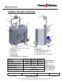
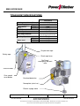
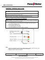
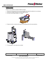
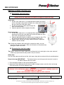
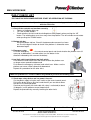
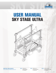
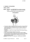
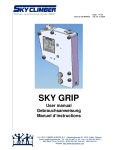
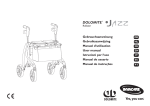
BMU WORKCAGE
USER MANUAL
BMU WORKCAGE
CONFORM TO THE MACHINE DIRECTIVE
2006/42/EC and to EN1808 (1999)
All persons operating this equipment must read and completely
understand this manual.
Any operation in violation of these instructions is at the operator's
own risk.
Keep this manual with the equipment at all times.
Only use POWER CLIMBER original spare parts and steel wire rope.
Manufacturer
POWER CLIMBER B.V.B.A.
Satenrozen 7
B- 2550 Kontich
BELGIUM
www.PowerClimber.be
Tel: +32-3-451.05.00
Fax: +32-3-451.05.01
e-mail: [email protected]
Reference: 38825-E
Revision: Rev. B
Tel. +32-3-451 05 00
Issue date: 2010-NOV-19
E-mail: [email protected]
Website: www.PowerClimber.be
Page: 1 of 10
Fax +32-3-451 05 01
This document and all copies are the property of Power Climber BVBA. All dimensions and data are indicative only.
The user must ensure that the equipment complies with local rules and regulations.
BMU WORKCAGE
TABLE OF CONTENTS
TABLE OF CONTENTS ............................................................................................. 2
DESCRIPTION OF BMU WORKCAGE...................................................................... 2
GENERAL VIEW BMU WORKCAGE ........................................................................ 3
TITAN HOIST SPECIFICATIONS .............................................................................. 4
CENTRAL CONTROL BOX (CCB) ............................................................................ 5
SAFETY FUNCTIONS................................................................................................ 6
UNPACKING .............................................................................................................. 7
INSTALLATION.......................................................................................................... 8
INSTALLATION (Continued)..................................................................................... 9
DAILY CHECK LIST................................................................................................. 10
DAILY CHECK LIST (Continued)............................................................................ 11
CHECK LIST AFTER USE ....................................................................................... 11
APPENDIX 1: Testing & Commissioning .................................................. 1 Page(s)
APPENDIX 2: Description of safety devices ............................................. 3 Page(s)
APPENDIX 3: Storage & Maintenance....................................................... 1 Page(s)
APPENDIX 4: Adjustment of wire winder couplings................................ 1 Page(s)
APPENDIX 5: Specifications of the steel wire ropes ............................... 1 Page(s)
APPENDIX 6: General precautions and limitations.................................. 3 Page(s)
APPENDIX 7: Titan overload adjustment.................................................. 1 Page(s)
APPENDIX 8: Troubleshooting .................................................................. 1 Page(s)
DESCRIPTION OF BMU WORKCAGE
BMU (Building Maintenance Unit) workcages are intended to be permanently installed and
dedicated to a specific building or structure. They are to be used by operators for inspection,
cleaning and maintenance of a building where the general public may have access below the
suspended workcage.
The BMU workcage consists of aluminium cage, fixed to a steel stirrup frame. The lifting traction
hoist is fixed to this stirrup.
The suspension and the safety wires are wound up by means of a powered twin-drum wire winder
unit, which is situated below the hoist.
The platform is controlled from a central control box located in the platform.
Reference: 38825-E
Tel. +32-3-451 05 00
Issue date: 2010-NOV-19
Revision: Rev. B
E-mail: [email protected]
Website: www.PowerClimber.be
Page: 2 of 10
Fax +32-3-451 05 01
This document and all copies are the property of Power Climber BVBA. All dimensions and data are indicative only.
The user must ensure that the equipment complies with local rules and regulations.
BMU WORKCAGE
GENERAL VIEW BMU WORKCAGE
10
1
12
9
3
2
14
8
11
4
7
13
1. Top Limit and Ultimate Top limit switch
2. Titan hoist
3. Central Control Box
4. Wire winder
5. Castor rollers
6. Bottom trip bar
7. Soft wall rollers
8. Storage bin for power supply cable
5
6
9. Steel stirrup
10. Top roller
11. Internal cladding winding drum
12. Slack rope safety device
13. Footstep for in/out
14. Safety eye (harness attachment)
700 mm (
1100 mm
1500 mm
Self-weight (*)
150 kg
160 kg
170 kg
Safe Working Load (SWL)
1200 N
1200 N
1200 N
Length (L)
Number of persons
1
Climbing speed:
8.5 m/min.
Safety and suspension rope
Reference: 38825-E
Tel. +32-3-451 05 00
Ø 8.4mm (52.3kN)
Issue date: 2010-NOV-19
(*) Self weight is
without steel wire
ropes and supply
cable.
Add 0.85 kg/m for
steel wire rope and
power supply cable.
[Use flexible power
cable: HO7RNF]
Revision: Rev. B
E-mail: [email protected]
Website: www.PowerClimber.be
Page: 3 of 10
Fax +32-3-451 05 01
This document and all copies are the property of Power Climber BVBA. All dimensions and data are indicative only.
The user must ensure that the equipment complies with local rules and regulations.
BMU WORKCAGE
TITAN HOIST SPECIFICATIONS
Titan 403 PI
Working Load Limit (W.L.L.)
Power Supply
RUN
Amperage at
W.L.L.
START
Motor Power
Motor Speed
400 kg
3 x 400V / 50Hz + N + E
2.5 A
7.5 A
0.74 kW
1400 RPM
8.4 mm
(breaking load 52.3 kN)
8.5 m/min
60 dBA
64 dBA
69 dBA
Wire Rope Diameter
Hoisting Speed
Noise level
UP
DOWN
MANUAL
Suspension rope
Safety rope
Slack rope lever
‘No Power’
emergency descent
lever
Electric motor
Over speed
reset button
Overload detection
Nameplate (serial no.)
Electric supply cable
Reference: 38825-E
Tel. +32-3-451 05 00
Issue date: 2010-NOV-19
Revision: Rev. B
E-mail: [email protected]
Website: www.PowerClimber.be
Page: 4 of 10
Fax +32-3-451 05 01
This document and all copies are the property of Power Climber BVBA. All dimensions and data are indicative only.
The user must ensure that the equipment complies with local rules and regulations.
BMU WORKCAGE
CENTRAL CONTROL BOX (CCB)
Main Switch: Turns on the main power.
‘Power on’ indicator: The GREEN indicator lights up when the supply cable is
connected correctly and the main switch is on.
Emergency stop: The emergency stop immediately cuts ALL power. In order to switch
the power back on, turn the button in the direction indicated by the arrow.
‘Hold-to-run’ buttons for operating up- and downward
Bypass – button: To be used when the platform needs to be set entirely at the bottom
or for de-reeving the steel wires from the hoist.
Problem indicator: The RED indicator lights up when:
• The electro-mechanical overload limiter was activated. (Overload condition =
useful load exceeded by 25%)
• The Emergency stop is pressed
• The ultimate top limit is activated
• The thermal protection of the hoist motor is activated
UP/DOWN selector switch
Main Switch
Bypass
Emergency Button
‘Power on’ indicator
‘Problem’ indicator
Note:
→ The place of the buttons might change without warning. Always verify the name of the
button on the CCB to make sure you use the correct button.
→ Integrated Trolley controls are optional.
Reference: 38825-E
Tel. +32-3-451 05 00
Issue date: 2010-NOV-19
Revision: Rev. B
E-mail: [email protected]
Website: www.PowerClimber.be
Page: 5 of 10
Fax +32-3-451 05 01
This document and all copies are the property of Power Climber BVBA. All dimensions and data are indicative only.
The user must ensure that the equipment complies with local rules and regulations.
BMU WORKCAGE
SAFETY FUNCTIONS
HAZARD
SAFETY ACTION
RESULT
1.
Breaking of suspension
wire.
Suspension wire becomes
slack.
Slack rope safety device is
activated.
2.
Overspeed condition of
a hoist.
Overspeed safety device is
activated.
Safety device will grab the
safety wire and hold the
workcage.
Down direction is cut off.
Safety device will grab the
suspension wire, and hold
the workcage.
Down direction is cut off.
3.
4.
Overload condition or
the workcage is hooked
under a part of the
building.
Workcage is a hitting
part of the building, or
reaches ground level.
Overload detection device
is activated
Workcage will be stopped.
Up and down direction is
cut off.
Bottom limit trip bar is
activated.
Workcage will be stopped.
Down direction is cut off.
Workcage will be stopped.
Up direction is cut off.
5.
Workcage has reached
top-position.
Top limit switch is activated
by striker plate.
6.
Failure of top limit
switch.
Ultimate top limit is
activated by striker plate.
7.
Slack of suspension
wire.
Slack rope safety device
becomes activated.
8.
Slowly creeping down of
workcage.
9.
Power failure.
Reference: 38825-E
Tel. +32-3-451 05 00
Workcage will be stopped.
Up and down direction is
cut off.
Safety device will grab the
safety wire and hold the
workcage.
Down direction is cut off.
Safety device will grab the
suspension wire and hold
the workcage.
Down direction is cut off.
Workcage is descending
slowly enough for the
overspeed safety device to
be activated manually.
Release service brake
manually by pulling down
the emergency descent
lever.
Issue date: 2010-NOV-19
Workcage will move down
at a lower speed than the
normal downwards speed.
Revision: Rev. B
E-mail: [email protected]
Website: www.PowerClimber.be
Page: 6 of 10
Fax +32-3-451 05 01
This document and all copies are the property of Power Climber BVBA. All dimensions and data are indicative only.
The user must ensure that the equipment complies with local rules and regulations.
BMU WORKCAGE
UNPACKING
Follow the steps below to unpack the BMU workcage:
1. Remove all the protective foil from the packaging and inspect the platform for any damage.
2. Remove the wooden protection and the support bracket.
3. Position the workcage upright on its wheels.
4. Rotate the roller assembly at the top of the workcage back to the normal position.
5. The workcage is now ready to be installed.
Reference: 38825-E
Tel. +32-3-451 05 00
Issue date: 2010-NOV-19
Revision: Rev. B
E-mail: [email protected]
Website: www.PowerClimber.be
Page: 7 of 10
Fax +32-3-451 05 01
This document and all copies are the property of Power Climber BVBA. All dimensions and data are indicative only.
The user must ensure that the equipment complies with local rules and regulations.
BMU WORKCAGE
INSTALLATION
The workcage is suspended and fully tested at the Power Climber facility before packing and
shipping.
1.
Unpack the workcage and check for any damage.
2.
Position the workcage below the suspension system.
3.
Secure the male plug into the power socket.
IMPORTANT: An earth leakage circuit breaker (ELCB) of 30 mA and an overcurrent protection
device of 16A (Type C) must be used at the power source. Check that the
specifications of the electrical supply cable match the power requirement of the
platform and will avoid a voltage drop due to the cable length.
4.
Check that the hoist and wire winder turns when pushing the up button. The top of the
winder should rotate away from the workcage. Check that only the hoist turns when
pushing the down button.
Note: All three-phase workcages are fitted with phase protection and will not operate if the
phases are incorrectly connected. See troubleshooting section (in BMU Workcage
Appendix 8-E) for additional information on correct phase connection.
WARNING: DO NOT change any connection in the central control box.
Secure the power supply cable to the suspension system using the cable retainer.
5.
Make sure that the length of the steel wire rope is sufficient. (suspension and safety wires)
IMPORTANT: Required length of steel wire rope = the building height + 5 m.
6.
At roof level, uncoil the safety rope and lay it on the roof surface. Attach the safety rope to
the suspension system with the safety hook fitted to the rope and lower the rope to the
ground.
7.
Reeve the safety ropes (see 'Reeving the steel cables').
8.
At roof level, uncoil the suspension rope and lay it on the roof surface. Attach the
suspension rope to the suspension system with the safety hook fitted to the rope and
lower the rope to the ground.
9.
Reeve the suspension ropes (see 'Reeving the steel cables').
Tip: By separately reeving the safety rope and the suspension rope you can avoid getting them
twisted together.
10.
Proceed with Testing and Commissioning as described in BMU Workcage appendix 3E.
11.
Only after completing these tests, can you take a first trip to the top of the building and fit
the top limit switch striker plate.
IMPORTANT:
CLAMP THE STRIKER PLATE TO THE SAFETY ROPE ONLY
THE SUSPENSION ROPE PASSES FREELY THROUGH THE SLOT IN THE PLATE
Reference: 38825-E
Tel. +32-3-451 05 00
Issue date: 2010-NOV-19
Revision: Rev. B
E-mail: [email protected]
Website: www.PowerClimber.be
Page: 8 of 10
Fax +32-3-451 05 01
This document and all copies are the property of Power Climber BVBA. All dimensions and data are indicative only.
The user must ensure that the equipment complies with local rules and regulations.
BMU WORKCAGE
INSTALLATION (Continued)
A) Reeving the steel wire ropes
WARNING:
Always reeve the safety rope first before reeving the suspension rope.
Safety rope
1. Put the slack rope lever in its upright position to open the clamps
of the slack rope safety device and push the safety cable through
the rear slot of the slack rope safety.
2. Put the tail end of the safety rope through the
hole in the wire winder.
3. Operate upward in order to tighten the cable.
Suspension rope
1. Put the slack rope lever in its upright position and put the cable
through the eye of the slack rope lever and at the top of the hoist
Push until you experience resistance.
2. Operate upward to allow the cable to move through the hoist. The
tail end of the cable will come out at the bottom of the hoist.
3. Repeat step 2 and 3 of the safety cable to load the suspension
cable on the wire winder.
Tip: If there are problems with reeving the suspension cable, you can
bend the tail end of the cable a little in the direction of the plate before
putting the cable in the hoist.
B) Dereeving the steel wire ropes
Tip: Always unreeve the safety cables first and keep the hoist cable tight so the slack cable fall
safety stays open and the safety cable is easy to remove.
Safety rope
Pull the safety rope manually out of the slack rope safety device and out of the wire winding drum.
Suspension rope IMPORTANT:
The bottom trip bar must be bypassed manually in order to
be able to dereeve the hoist cable.
1. Push the bypass button on the central control panel.
2. Operate the hoist downward until the hoist cable no longer comes out of the hoist at the top.
Then, pull out the rest of the cable by hand.
Warning:
REEVING THE SUSPENSION CABLE INCORRECTLY IS THE MOST COMMON CAUSE OF
ENTANGLEMENT OF CABLES
SOLELY USE ORIGINAL POWER CLIMBER STEEL CABLES
Reference: 38825-E
Tel. +32-3-451 05 00
Issue date: 2010-NOV-19
Revision: Rev. B
E-mail: [email protected]
Website: www.PowerClimber.be
Page: 9 of 10
Fax +32-3-451 05 01
This document and all copies are the property of Power Climber BVBA. All dimensions and data are indicative only.
The user must ensure that the equipment complies with local rules and regulations.
BMU WORKCAGE
DAILY CHECK LIST
TEST MUST BE PERFORMED BEFORE START OF OPERATION OF THE BMU.
Inspect the platform visually to detect damage, loose or missing parts before beginning
with the check list.
1. Check if the controls are function correctly:
•
‘Power on’ indicator lights up:
•
‘UP’ and ‘DOWN’ buttons
•
Check whether the hoist and the winding drum work properly when pushing the ‘UP’
button. The winding drum must turn away from the platform. The wire winder cannot rotate
when pushing the ‘DOWN' button.
2. Bottom trip bar
Raise the bottom trip bar. Check if the downward movement has been
cut. Push the bypass button to check if the platform is allowed to move
downward again.
3. Emergency stop
Push the emergency stop on the central control panel and check whether the platform can still
move up- or downward. ( to undo action, turn the button in the
direction indicated by the arrow on the button)
4. top limit switch and ultimate top limit switch
Push down the end switch lever and check whether the platform can
no longer move upward but downward.
Push down the emergency (ultimate) end switch lever. Make sure the
platform can move neither upward nor downward.
Repeat this procedure for the other hoist.
Move the platform to 1-2 metres above the ground to perform the following tests.
5. Slack rope safety device and ‘no power’ descent.
Cut the power supply using the main switch at the central control panel.
Pull up the brake lever on one hoist and check if you are able to lower
the hoist at a controlled speed.
Continue pushing until the slack cable fall safety is activated (at about
10 degrees) so the platform cannot slope further.
Repeat the procedure by manually lowering the other hoist.
Reference: 38825-E
Tel. +32-3-451 05 00
Issue date: 2010-NOV-19
Revision: Rev. B
E-mail: [email protected]
Website: www.PowerClimber.be
Page: 10 of 10
Fax +32-3-451 05 01
This document and all copies are the property of Power Climber BVBA. All dimensions and data are indicative only.
The user must ensure that the equipment complies with local rules and regulations.
BMU WORKCAGE
DAILY CHECK LIST (Continued)
6. Steel wire rope and power supply cable
Move the platform all the way to the top. Along the way check the safety cables and the hoist
cables for kinks, broken wires or other damage.
At the same time, check the supply cable for damage.
IMPORTANT: In every day use, always be mindful of possible damage of the steel cables or the
supply cable.
See BMU Workcage Appendix 5-E: “Steel wire rope specifications” for further details on the
steel cable.
NEVER USE MATERIAL THAT DOES NOT FUNCTION PROPERLY!
CHECK LIST AFTER USE
1. Turn off the main switch on the central control panel. Lock if necessary.
2. Disengage the supply cable.
3. If the platform is not used for a longer period, it should be stored.
See BMU Workcage Appendix 3-E: “Storage and maintenance” for more details.
USE OF HAND WHEEL FOR MOVING UPWARD WITHOUT POWER SUPPLY
This might be necessary to reset the overspeed- and /or slack rope safety device
during power failure when one of the safety devices has come in.
1. Turn off the main switch on the central control panel (to prevent
unwanted movement of the motor when suddenly regaining
power).
2. Remove the plastic cover at the top of the motor shield to install
the hand wheel.
3. Take the hand wheel and insert it in the hole at the top of the
motor.
4. Turn the hand wheel simultaneously counter clockwise and lift
the brake lever to open the brake.
5. Release the brake lever and repeat the procedure, until:
In case of overspeed: the yellow reset button can be
reset.
In case of slack rope: the suspension cable is no longer slack
TIP: Hold the hand wheel firmly while the brake opens to prevent further lowering.
6. After use, put the plastic cover back in the hole and put the hand wheel back in its storage
place!
7. Put the main switch back on. If the power is restored you can continue working.
Else you can use the emergency descent lever to lower to ground level.
Reference: 38825-E
Tel. +32-3-451 05 00
Issue date: 2010-NOV-19
Revision: Rev. B
E-mail: [email protected]
Website: www.PowerClimber.be
Page: 11 of 10
Fax +32-3-451 05 01
This document and all copies are the property of Power Climber BVBA. All dimensions and data are indicative only.
The user must ensure that the equipment complies with local rules and regulations.