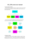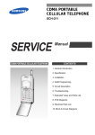
1
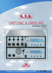
URPT/MIC & URPR/ MIC USER MANUAL VOLUME1 Manufactured by R.V.R ELETTRONICA S.p.A. Italy File Name: URPT&URPR_MIC_ING_1.0.indb Version: 1.0 Date: 20/05/2011 Revision History Date Version 20/05/2011 1.0 Reason First Version Editor J. H. Berti URPT/MIC & URPR/ MIC - User Manual Version 1.0 © Copyright 2011 R.V.R. Elettronica SpA Via del Fonditore 2/2c - 40138 - Bologna (Italia) Telephone: +39 051 6010506 Fax: +39 051 6011104 Email: [email protected] Web: www.rvr.it All rights reserved Printed and bound in Italy. No part of this manual may be reproduced, memorized or transmitted in any form or by any means, electronic or mechanic, including photocopying, recording or by any information storage and retrieval system, without written permission of the copyright owner. ELETTRONICA URPT/MIC & URPR/MIC Table of Contents 1. 2. 3. 3.1 3.2 4. 4.1 4.2 4.3 4.4 4.5 4.6 4.7 4.8 4.9 4.10 5. 5.1 5.2 5.3 5.4 6. 6.1 6.2 6.3 6.4 7. 7.1 7.2 Preliminary Instructions Warranty First Aid Treatment of electrical shocks Treatment of electrical Burns General Description Unpacking Features URPT/MIC Frontal Panel Description URPT/MIC Rear Panel Description URPT/MIC Connector Description URPR/MIC Frontal Panel Description URPR/MIC Rear Panel Description URPR/MIC Connector Description URPT/MIC Technical Description URPR/MIC Technical Description URPT/MIC quick guide for installation and use Preparation First power-on and setup Operation Management Firmware URPR/MIC quick guide for installation and use Preparation First power-on and setup Operation Management Firmware Identification and Access to the Modules URPT/MIC Upper View URPR/MIC Upper View User Manual Rev. 1.0 - 20/05/11 1 1 2 2 2 3 3 3 7 8 9 11 12 13 15 17 18 18 21 22 24 30 30 21 22 24 40 40 40 URPT/MIC & URPR/MIC ELETTRONICA This page was intentionally left blank ii Rev. 1.0 - 20/05/11 User Manual URPT/MIC & URPR/MIC ELETTRONICA IMPORTANT The symbol of lightning inside a triangle placed on the product, evidences the operations for which is necessary gave it full attention to avoid risk of electric shocks. The symbol of exclamation mark inside a triangle placed on the product, informs the user about the presence of instructions inside the manual that accompanies the equipment, important for the efficacy and the maintenance (repairs). Make sure both are properly connected. 1. Preliminary Instructions Operation of this equipment in a residential area may cause radio interference, in which case the user may be required to take adequate measures. • General Warnings This equipment should only be operated, installed and maintained by “trained” or “qualified” personnel who are familiar with risks involved in working on electric and electronic circuits. “Trained” means personnel who have technical knowledge of equipment operation and who are responsible for their own safety and that of other unqualified personnel placed under their supervision when working on the equipment. “Qualified” means personnel who are trained in and experienced with equipment operation and who are responsible for their own safety and that of other unqualified personnel placed under their supervision when working on the equipment. The specifications and data contained herein are provided for information only and are subject to changes without prior notice. R.V.R. Elettronica S.p.A. disclaims all warranties, express or implied.While R.V.R. Elettronica S.p.A. attempts to provide accurate information, it cannot accept responsibility or liability for any errors or inaccuracies in this manual, including the products and the software described herein. R.V.R. Elettronica S.p.A. reserves the right to make changes to equipment design and/or specifications and to this manual at any time without prior notice. WARNING: Residual voltage may be present inside the equipment even when the ON/OFF switch is set to Off. Before servicing the equipment, disconnect the power cord or switch off the main power panel and make sure the safety earth connection is connected. Some service situations may require inspecting the equipment with live circuits. Only trained and qualified personnel may work on the equipment live and shall be assisted by a trained person who shall keep ready to disconnect power supply at need. This product is a radio transmitter suitable for frequencymodulation audio radio broadcasting. Its operating frequencies are not harmonised in designated user countries. Before operating this equipment, user must obtain a licence to use radio spectrum from the competent authority in the designated user country. Operating frequency, transmitter power and other characteristics of the transmission system are subject to restrictions as specified in the licence. R.V.R. Elettronica S.p.A. shall not be liable for injury to persons or damage to property resulting from improper use or operation by trained/untrained and qualified/unqualified persons. WARNING: The equipment is not water resistant. Any water entering the enclosure might impair proper operation. To prevent the risk of electrical shock or fire, do not expose this equipment to rain, dripping or moisture. Please observe local codes and fire prevention rules when installing and operating this equipment. WARNING: This equipment contains exposed live parts involving an electrical shock hazard. Always disconnect power supply before removing any covers or other parts of the equipment. Ventilation slits and holes are provided to ensure reliable operation and prevent overheating; do not obstruct or cover these slits. Do not obstruct the ventilation slits under any circumstances. The product must not be incorporated in a rack unless adequate ventilation is provided or the manufacturer’s instructions are followed closely. WA R N I N G : T h i s e q u i p m e n t c a n r a d i a t e radiofrequency energy and, if not installed in compliance with manual instructions and applicable regulations, may cause interference with radio communications. WARNING: This equipment is fitted with earth connections both in the power cord and for the chassis. User Manual • Notice concerning product intended purpose and use limitations. 2. Warranty La R.V.R. Elettronica S.p.A. warrants this product to be free from defects in workmanship and its proper operation subject to the limitations set forth in the supplied Terms and Conditions. Please read the Terms and Conditions carefully, as purchase of the product or acceptance of the order acknowledgement imply acceptance of the Terms and Conditions. For the latest updated terms and conditions, please visit our web site at WWW.RVR.IT. The web site may be modified, removed or updated for any reason whatsoever without prior notice. The warranty will become null and void in the event the product enclosure is opened, the product is physically damaged, is repaired by unauthorised persons or is used for purposes other than its intended use, as well as in the event of improper use, unauthorised changes or neglect. In the event a defect is found, follow this procedure: 1 Contact the seller or distributor who sold the equipment; provide a description of the problem or malfunction for the event a quick fix is available. Sellers and Distributors can provide the necessary information to troubleshoot the most frequently encountered problems. Normally, Sellers and Distributors can offer a faster repair service than the Manufacturer would. Please note that Sellers can pinpoint problems due to wrong installation. 2 If your Seller cannot help you, contact R.V.R. Elettronica S.p.A. and describe the problem; if our staff deems it appropriate, you will receive an authorisation to return the equipment along with suitable instructions; 3 When you have received the authorisation, you may return the unit. Pack the unit carefully before shipment; use the original packaging whenever possible and seal the package perfectly. The customer bears all risks of loss (i.e., R.V.R. shall not be liable for loss or damage) until the package reaches the R.V.R. factory. For this reason, we recommend insuring the goods for their full value. Returns must be sent on a C.I.F. basis (PREPAID) to the address stated on the authorisation as specified by the R.V.R. Service Manager. Rev. 1.0 - 20/05/11 / 42 URPT/MIC & URPR/MIC ELETTRONICA Units returned without a return authorisation may be rejected and sent back to the sender. 4 Be sure to include a detailed report mentioning all problems you have found and copy of your original invoice (to show when the warranty period began) with the shipment. Please send spare and warranty replacement parts orders to the address provided below. Make sure to specify equipment model and serial number, as well as part description and quantity. 3.1.2 R.V.R. Elettronica S.p.A. Via del Fonditore, 2/2c 40138 BOLOGNA ITALY Tel. +39 051 6010506 3. First Aid All personnel engaged in equipment installation, operation and maintenance must be familiar with first aid procedures and routines. 3.1 Electric shock treatment 3.1.1 If the victim is unconscious Lay the victim down on his/her back on a firm surface. • the neck and tilt the head backwards to free Do not stop chest compressions while giving artificial breathing. • Call for medical help as soon as possible. If the victim is conscious • Cover victim with a blanket. • Try to reassure the victim. • Loosen the victim’s clothing and have him/her lie down. • Call for medical help as soon as possible. 3.2 Treatment of electric burns 3.2.1 Large burns and broken skin Follow the first aid procedures outlined below. • • • Cover affected area with a clean cloth or linen. • Do not break any blisters that have formed; remove any clothing or fabric that is stuck to the skin; apply adequate ointment. • Administer adequate treatment for the type of accident. • Get the victim to a hospital as quickly as possible. • Elevate arms and legs if injured. If medical help is not available within an hour, the victim is conscious and is not retching, administer a solution of table salt and baking soda (one teaspoon of table salt to half teaspoon of baking soda every 250 ml of water). the airway system (Figure 1). Have the victim slowly drink half a glass of solution for four times during a period of 15 minutes. Stop at the first sign of retching. Do not administer alcoholic beverages. Figure 1 • If needed, open the victim’s mouth and check for breathing. • If there is no breathing, start artificial respiration without delay (Figure 2) as follows: tilt the head backwards, pinch the nostrils, seal your mouth around the victim’s mouth and give four fast rescue breaths. 3.2.2 Minor burns • Apply cold (not ice cold) strips of gauze or dress wound with clean cloth. • Do not break any blisters that have formed; remove any clothing or fabric that is stuck to the skin; apply adequate ointment. • If needed, have the victim change into clean, dry clothing. • Administer adequate treatment for the type of accident. • Get the victim to a hospital as quickly as possible. • Elevate arms and legs if injured. Figure 2 • / 42 Check for heartbeat (Figure 3); if there is no heartbeat, begin chest compressions immediately (Figure 4) placing your hands in the centre of the victim’s chest (Figure 5). Figure 3 Figure 4 Figure 5 • One rescuer: give 2 quick rescue breaths after each 15 compressions. • Two rescuers: one rescue breath after each 5 compressions. Rev. 1.0 - 20/05/11 User Manual URPT/MIC & URPR/MIC ELETTRONICA 4. General Description The URPT/MIC and URPR/MIC (microphonic version) are, respectively a broadband radio transmitter and receiver for the transport of audio signals as an auxiliary to the frequency modulation sound broadcasting. The URPT/MIC is designed to work in an optimum way when connected to the receiver URPR/MIC. This type of equipment is designed to be used as a portable unit. This narrow-band modulator is designed to carry “out of studio” interviews by journalists, direct “on the field” and so on; while the receiver is designed for employement also on motor vehicles (both light and heavy), or installation with low enviromental impact supplies by batteries or photovoltaic panels. 4.1 Unpacking The package contains: 1 URPT/MIC and/or URPR/MIC 1 User Manual 1 Mains power cable The following accessories are also available from Your R.V.R. Dealer: • Accessories, spare parts and cables 4.2 Features The standard working frequency bands are the following: • /B10: 190 ÷ 310 • /B20: 315 ÷ 400 • /B30: 405 ÷ 465 • /B40: 470 ÷ 545 • /B50: 780 ÷ 885 • /B60: 890 ÷ 970 Note: the working frequency (and therefore the band) should be indicated when the order for such product is placed. Note: upon request, these links are available at other frequency bands and steps, please contactact RVR in order to check the availability of modules at the required frequency. The URPT/MIC contain a low-pass filter that reduces the harmonic emission to provided for by international standards (CCIR, FCC or ETSI) and can be connected directly to the antenna. User Manual Rev. 1.0 - 20/05/11 / 42 URPT/MIC & URPR/MIC ELETTRONICA The RF power section of URPT/MIC features a MOSFET module delivering up to 40W output power. Operating frequency stability is ensured by a temperature-compensated reference oscillator and is maintained by a PLL (Phase Locked Loop) system. The exciters will go into frequency lock within 30 seconds after power-on. On the front panel there are four input connectors for the balanced audio signal (impedance 2,2 Kohm) and its audio level controls, switches for the level selection (MIC-LINE), four switches to activate the prelistening service and its level control, switch to power on/off the service microphone. IMPORTANT: on service microphone input there is a bias voltage to use ELECTRET microphones, if the microphone in use does not need this bias voltage and you want to turn it off, move the jumper JP3 on the audio panel card (SL137PC1002) from position 2-3 to position 1-2. On rear panel are present the input mains connector, the RF output connector, the service connector and accessory connector for connection to external machine or rescue battery. In the standard version of the URPR/MIC, the demodulated signal is available in the MPX form (that is to say the complete basis signal band) and in the mono version. Moreover there is one connector used for SCA output as an option, the URPR/MIC can be equipped with a stereo decoder option. Also when this option is present, apart from the outputs for the LEFT and RIGHT channels, the outputs for the MPX signal are present and for the possible sub-carriers. On rear panel are present the input mains connector, the RF input connector, the service connector and accessory connector for connection to external machine or rescue battery. The important audio characteristics of this equipment are the low distorsion and intermodulation values and the high S/N level; another important quality both of the URPT/MIC and the URPR/MIC is its very simple construction and its easy use. Both the URPT/MIC and the URPR/MIC were designed in a modular way: the different functions are executed by modules connected directly with male and female connectors or with flat cables with connectors at both ends. This type of design makes the maintenance and the possible replacement of modules an easy operation. / 42 Rev. 1.0 - 20/05/11 User Manual URPT/MIC & URPR/MIC ELETTRONICA The microprocessor system includes an LCD display and an encoder that enable the interaction with the user, and implements the following functions for the transmitter: • Display of the modulation • Setting of the output power • Setting of the working frequency • Power Good feature (User-selectable output power alarm threshold). • Measurement and display of the working parameters of the transmitter • Communications with external devices such as programming systems, or telemetry systems, via SERVICE serial interface. These functions are implemented for the receiver: • Display of the modulation • Setting of the working frequency • Setting of the muting threshold • Measurement and display of the working parameters of the receiver • Communications with external devices such as programming systems, or telemetry systems, via SERVICE serial interface. The URPT/MIC and URPR/MIC management firmware is based on a menu system. User has four navigation buttons available to browse submenus: ESC , , , ed ENTER. The status of the unit is indicated by four LEDs which are present on the front pannel: • ENCODER ON, POWER ON, PLL LOCK, PWR OUT FOLDBACK, RF MUTE for URPT/MIC. • ENCODER PRESENT, POWER ON, PLL LOCK, PILOT PRESENT, AUDIO MUTE for URPR/MIC. Both the transmitter and the receiver, through the SERVICE connector, have an input for the external 12 or 24 VDC supply. This auxiliary supply source, that can be realized by the user with the help of rescue batteries, is automatically used in case of AC voltage absence. User Manual Rev. 1.0 - 20/05/11 / 42 URPT/MIC & URPR/MIC ELETTRONICA 4.3 URPT/MIC Frontal Panel Description [1] INP1 KNOB INPUT 1 level adjusting knob. [2] INP1 LED Green LED - light on when the INPUT 1 is in prelistening. [3] INP1 BUTTON Push button to put INPUT 1 in prelistening. [4] INP2 KNOB INPUT 2 level adjusting knob. [5] INP2 LED Green LED - light on when the INPUT 2 is in prelistening. [6] INP2 BUTTON Push button to put INPUT 2 in prelistening. [7] INP3 KNOB INPUT 3 level adjusting knob. [8] INP3 LED Green LED - light on when the INPUT 3 is in prelistening. [9] INP3 BUTTON Push button to put INPUT 3 in prelistening. [10] INP4 KNOB INPUT 4 level adjusting knob. [11] INP4 LED Green LED - light on when the INPUT 4 is in prelistening. [12] INP4 BUTTON Push button to put INPUT 4 in prelistening. [13] MIC ON LED Green LED - light on when the microphone input is selected. [14] MIC BUTTON Push button to enable the microphone input. [15] MIC GAIN Adjustment trimmer of volume for microphone jack. [16] HEADPHONES Jack connector for headphones. Dual-mono output. [17] DISPLAY Liquid crystals display. [19] ENCODER ON Red LED - light on when the 27 Hz subtone is enabled. [19] POWER ON Green LED - light on when the exciter is working. [20] PLL LOCK Green LED - light on when PLL is locked on woprking frequency. [21] PWR OUT FOLDBACK Yellow LED - light on when the Automatic Gain Control function works correctly. [22] R.F. MUTE Yellow LED - light on when the exciter’s power output is inhibited by an external interlock command. [23] CONTRAST Display contrast adjusting trimmer. [24] MIC/LINE SWITCH 1 Commutation switch between microphone and line level. [25] INP 1 XLR balanced connector for microphonic or line input 1. [26] MIC/LINE SWITCH 2 Commutation switch between microphone and line level. [27] INP 2 XLR balanced connector for microphonic or line input 2. [28] MIC/LINE SWITCH 3 Commutation switch between microphone and line level. [29] INP 3 XLR balanced connector for microphonic or line input 3. [30] MIC/LINE SWITCH 4 Commutation switch between microphone and line level. [31] INP 4 XLR balanced connector for microphonic or line input 4. [32] MIC Jack connector for microphone. / 42 Rev. 1.0 - 20/05/11 User Manual URPT/MIC & URPR/MIC ELETTRONICA [33] POWER [34] ESC [35] [36] [37] ENTER User Manual ON/OFF switch. Push button to exit from a menu. Push button to move in the menu system and to modify the parameters. Push button to move in the menu system and to modify the parameters. Push button to confrim a parameter and to enter in a menu. Rev. 1.0 - 20/05/11 / 42 URPT/MIC & URPR/MIC ELETTRONICA 4.4 URPT/MIC Rear Panel Description [1] PLUG [2] R.F. OUTPUT [3] ACCESSORY [4] FUSE BLOCK [5] SERVICE / 42 VDE plug for mains supply. RF output connector, N-type, 50 Ω DB15 male connector for interconnection with other devices (i.e. external battery). Fuse carrier.Use a screwdriver to access the fuse. Includes a fuse for general protection regarding power supply. DB15 female connector for the telemetry of equipment. Rev. 1.0 - 20/05/11 User Manual URPT/MIC & URPR/MIC ELETTRONICA 4.5 URPT/MIC Connector Description 4.5.1 Service Type: Female DB15 1 Pin Name Type 1 Interlock IN 9 2 FWD Foldback 3 GND 4 Reserved 5 VPA Tlm ANL OUT 6 FWD Tlm ANL OUT 7 Power Good DIG OUT 8 GND 9 GND 10 Ext AGC RFL IN 11 Reserved 12 IPA Tlm ANL OUT 13 RFL Tlm ANL OUT 14 On cmd DIG IN 15 OFF cmd DIG IN Meaning Pull-up 5V (if grounded, it inhibits the RF power) Ext. signal,1-12V, for power limitation (AGC) Ground PA power supply voltage: 3.9V F.S. Forward power: 3.9V F.S. Open collector (if grounded, it enable the power good). Ground Ground Ext. signal,1-12V, for power limitation (AGC) PA power supply current: 3.9V F.S. Reflected power: 3.9V F.S. One grounded pulse (500 ms) enables RF. One grounded pulse (500 ms) disables RF. 4.5.2 Accessory Type: Male DB15 1 Pin 1 9 2 3 4 5 6 7 8 9 10 11 12 13 14 15 User Manual Meaning GND DC+ (IN) from 9 to 30V DC+ (IN) from 9 to 30V External Balanced Audio External Balanced Audio DC+ (IN) from 9 to 30V DC+ (IN) from 9 to 30V GND DC+ (IN) from 9 to 30V DC+ (IN) from 9 to 30V GND GND Not Connected DC+ (IN) from 9 to 30V Stand by (IN) Pull-up 5V; if GND then RF OK Rev. 1.0 - 20/05/11 / 42 URPT/MIC & URPR/MIC ELETTRONICA 4.5.3 Left (MONO) & Right Type: XLR Female 1 2 3 10 / 42 GND Positive Negative Rev. 1.0 - 20/05/11 User Manual URPT/MIC & URPR/MIC ELETTRONICA 4.6 URPR/MIC Frontal Panel Description [1] [2] [3] [4] [5] [6] [7] [8] [9] LOUDSPEAKER Mono output speaker. KNOB Output level adjusting knob for headphones. HEADPHONES Jack connector for headphones. Dual-mono output. DISPLAY Liquid crystals display. ENCODER PRESENTRed LED - light on when the 27 Hz subtone is present. POWER ON Green LED - light on when the receiver is working. PLL LOCK Green LED - light on when PLL is locked on working frequency. PILOT PRESENT Yellow LED - not used. AUDIO MUTE Yellow LED - light on when the muting is activated, which means that the input signal has decreased under the defined threshold. [10] CONTRAST Display contrast adjusting trimmer. [11] OUT 1/R XLR balanced connector for MONO output 1 or RIGHT. [12] ADJ ±12dBu Level adjusting trimmer for MONO output 1 or RIGHT. [13] OUT 1/R XLR balanced connector for MONO output 2 or LEFT. [14] ADJ ±12dBu Level adjusting trimmer for MONO output 2 or LEFT. [15] OUT 3/MPX BNC unbalanced connector for MONO output 3 or MPX. [16] ADJ ±12dBu Level adjusting trimmer for MONO output 3 or MPX. [17] OUT 4/SCA BNC unbalanced connector for MONO output 4 or SCA. [18] ADJ ±12dBu Level adjusting trimmer for MONO output 4 or SCA. [19] POWER ON/OFF switch. [20] ESC Push button to exit from a menu. [21] Push button to move in the menu system and to modify the parameters. [22] Push button to move in the menu system and to modify the parameters. [23] ENTER Push button to confrim a parameter and to enter in a menu. User Manual Rev. 1.0 - 20/05/11 11 / 42 URPT/MIC & URPR/MIC ELETTRONICA 4.7 URPR/MIC Rear Panel Description [1] PLUG [2] R.F. INPUT [3] ACCESSORY [4] FUSE BLOCK [5] SERVICE 12 / 42 VDE plug for mains supply. RF input connector, N-type, 50 Ω DB15 male connector for interconnection with other devices (i.e. external battery). Fuse carrier.Use a screwdriver to access the fuse. Includes a fuse for general protection regarding power supply. DB15 female connector for the telemetry of equipment. Rev. 1.0 - 20/05/11 User Manual URPT/MIC & URPR/MIC ELETTRONICA 4.8 URPR/MIC Connector Description 4.8.1 Service Type: Female DB15 1 Pin Name Type 1 Mute IN 9 2 Not Used 3 GND 4 Not Used 5 Not Used 6 Not Used 7 Ext TX ON DIG OUT 8 GND 9 GND 10 Not Used 11 Not Used 12 Not Used 13 Not Used 14 AF On cmd DIG IN 15 AF OFF cmd DIG IN Meaning Pull-up 5V; if grounded, it inhibits the Audio) Ground Open collector, enabled when power exceeds the set threshold Ground Ground One grounded pulse (500 ms) enables the AF. One grounded pulse (500 ms) disables the AF. 4.8.2 Accessory Type: Male DB15 1 Pin 1 9 2 3 4 5 6 7 8 9 10 11 12 13 14 15 User Manual Meaning GND DC+ (IN) from 9 to 30V DC+ (IN) from 9 to 30V Not Used Not Used DC+ (IN) from 9 to 30V DC+ (IN) from 9 to 30V GND DC+ (IN) from 9 to 30V DC+ (IN) from 9 to 30V GND GND Not Connected DC+ (IN) from 9 to 30V Stand by (IN) Pull-up 5V; if GND then RF OK Rev. 1.0 - 20/05/11 13 / 42 URPT/MIC & URPR/MIC ELETTRONICA 4.8.3 Left (MONO) & Right Type: XLR Male 1 2 3 14 / 42 GND Positive Negative Rev. 1.0 - 20/05/11 User Manual URPT/MIC & URPR/MIC ELETTRONICA 4.9 URPT /MIC Technical Description Parameters GENERALS URPT/MIC/B… Conditions Value Rated output power /B10: 30 W /B20: 30 W /B30: 30 W /B40: 40 W /B50: 20 W /B60: 20 W Modulation type Direct carrier frequency modulation Operational mode Display Environmental working temperature ALC ON, ALC OFF Alphanumerical LCD - 2 x 16 Frequency range (other frequency on request) Attention: the frequency work bandwith is 50MHz from 190 to 315 MHz and 26 MHz from 315 to 970 MHz /B10: 135 ÷ 185 /B20: 215 ÷ 265 /B30: 300 ÷ 350 /B40: 430 ÷ 480 /B50: 780 ÷ 885 /B60: 890 ÷ 970 Frequency programmability Frequency stability Modulation Capability Spurious & harmonic suppression from -10 °C to 50 °C WT from -10°C to 50°C 5 Khz step, other step available upon request ±1 ppm 7,5 KHz <70 dBc Asynchronous AM S/N ratio Referred to 100% AM, without de-emphasis 60 dBc Synchronous AM S/N ratio Referred to 100% AM, FM deviation 400Hz sine, without deemphasis 50 dBc ( @ ± 7,5 kHz peak of deviation) Audio Filters 5 / 7,5 / 10 / 12,5 Khz Preemphasis 0, 50ȝS (CCIR), 75ȝS (FCC), 750 ȝS MONO OPERATION S/N FM MPX OPERATION S/N FM Frequency response Total Harmonic Distortion STEREO OPERATION S/N FM Frequency response Total Harmonic Distortion Stereo separation RMS , HPF 20Hz LPF 23 kHz, 50 ȝS deemphasis 52 dB (RMS @ ± 7,5 kHz peak) RMS, HPF 20Hz - no LPF Not available 40 Hz ÷ 100 KHz THD+N 40 Hz ÷ 100 KHz Not available Not available RMS @ ± 75 kHz peak, HPF 20Hz - LPF 23 kHz, 50 ȝS deemphasis, L & R demodulated Not available 40 Hz ÷ 15 KHz THD+N 40 Hz ÷ 15 KHz Not available Connector Type Impedance Connector Type Impedance Connector Type Impedance Connector Type Impedance XLR F balanced 600, 2,2 or 10 k (Ohm), selectable with internal solder pad XLR F balanced 600 2,2 k or 10 k (Ohm), selectable with internal solder pad XLR F unbalanced 600, 2,2 k or 10 k (Ohm), selectable with internal solder pad XLR F unbalanced 600, 2,2 k or 10 k (Ohm), selectable with internal solder pad Not available Not available AUDIO INPUTS Input 1 Input 2 Input 3 Input 4 User Manual Rev. 1.0 - 20/05/11 15 / 42 URPT/MIC & URPR/MIC Service microphone OUTPUTS RF output Headphone outptut AUXILIARY CONNECTIONS Accessory Interface Telemetry Interface POWER REQUIREMENTS AC Primary power DC Power Input ELETTRONICA Connector Type Type Impedance Type Impedance Level N Type 50 Ohm 3,5 mm Jack 25 Ohm Max 200 mW Connector Connector DB15 M DB15 F AC Supply Voltage 90 ÷ 130 or 180 ÷ 250 VAC AC Power Consumption Connector DC Supply Voltage DC Current DC Power Consumption Connector MECHANICAL SPECIFICATION about 200 W IEC Standard 12-30 V < 13 A about 140 W DB15 (ACCESSORY) Phisical Dimensions (W x H x Weight 355x85x295 mm About 4 Kg SAFETY EN 60215:1989 + EN60215/A1:1992-07 + EN60215/A2:1994-09 STANDARD COMPLIANCE EMC EN 301 489-1 V1.4.1 (2002-08) + EN 301 489-11 V1.2.1 (2002-11) Spectrum Optimization EN 302 018-2 V1.2.1 (2005-06) /75-URPT 75 KHz modulation URPT/MIC option OPTIONS 16 / 42 3,5 mm Jack Mono, internal selectable phantom power (for electret mic) Rev. 1.0 - 20/05/11 User Manual URPT/MIC & URPR/MIC ELETTRONICA 4.10 URPR /MIC Technical Description Parameters GENERALS URPR/MIC/B… Conditions Value /B10: 135 ÷ 185 /B20: 215 ÷ 265 /B30: 300 ÷ 350 /B40: 430 ÷ 480 /B50: 780 ÷ 885 /B60: 890 ÷ 970 Frequency range (other frequency on request) Demodulation type FM Display Environmental working temperature RF input impedance Frequency programmability Alphanumerical LCD - 2 x 16 Frequency stability from -10 °C to 50 °C 50 Ohm from software step 10kHz ±1 ppm WT from -10°C to 50°C 0/25/50 ȝS (CCIR), 75ȝS (FCC), 750 ȝS IF: 70 MHz / 10,7 MHz / 700 kHz Deemphasis Intermediary Frequencies (IF) MONO OPERATION S/N FM RF INPUT -47 dBm, RMS @ ± 7 kHz peak, HPF 20Hz - LPF 23 kHz , 75 ȝS deemphasis 50 dB Frequency response 40 Hz ÷ 12,5 kHz, 75 ȝS deemphasis ± 0,5 dB Total Harmonic Distortion THD+N 40 Hz ÷ 15 KHz 3% Connector Impedance N Type 50 Ohm Connector Type Level Connector Type Level Connector Type Level Connector Impedance Type Impedance Level XLR Male balanced from -12 to 12 dBu BNC Unbalanced from -12 to 12 dBu DB15 M Balanced from -12 to 12 dBu BNC 50 Ohm 3,5 mm Jack 25 Ohm Max 200 mW Connector Connector DB15 M DB15 F AC Supply Voltage 90 ÷ 250 VAC INPUTS RF input OUTPUTS Mono front (one pair) Mono front Mono rear 10,7 MHz IF OUT Headphone outptut AUXILIARY CONNECTIONS Accessory Interface Telemetry Interface POWER REQUIREMENTS AC Primary power DC Power Input AC Power Consumption about 40 VA Connector DC Supply Voltage DC Current IEC Standard 12-30 V < 2,5 A DC Power Consumption about 30 W Connector DB15 (ACCESSORY) MECHANICAL SPECIFICATION Phisical Dimensions (W x H x D) 355x85x295 mm Weight About 3,5 Kg STANDARD COMPLIANCE User Manual SAFETY EN 60215:1989 + EN60215/A1:1992-07 + EN60215/A2:1994-09 EMC EN 301 489-1 V1.4.1 (2002-08) + EN 301 489-11 V1.2.1 (2002-11) Spectrum Optimization EN 302 018-2 V1.2.1 (2005-06) Rev. 1.0 - 20/05/11 17 / 42 URPT/MIC & URPR/MIC ELETTRONICA 5. URPT/MIC quick guide for installation and use This section provides a step-by-step description of equipment installation and configuration procedure. Follow these procedures closely upon first power-on and each time any change is made to general configuration, such as when a new transmission station is added or the equipment is replaced. Once the desired configuration has been set up, no more settings are required for normal operation; at each power-up (even after an accidental shutdown), the equipment defaults to the parameters set during the initial configuration procedure. The topics covered in this section are discussed at greater length in the next sections, with detailed descriptions of all hardware and firmware features and capabilities. Please see the relevant sections for additional details. IMPORTANT: When configuring and testing the transmitter in which the equipment is integrated, be sure to have the Final Test Table supplied with the equipment ready at hand throughout the whole procedure; the Final Test Table lists all operating parameters as set and tested at the factory. 5.1 Prepation 5.1.1 Preliminary checks Unpack the exciter and immediately inspect it for transport damage. Ensure that all connectors are in perfect condition. Provide for the following (applicable to operating tests and putting into service): √ Single-phase 90÷130 VAC or 180÷250 VAC mains power supply, with adequate earth connection. √ For operating tests only: dummy load with 50 Ohm impedance and adequate capacity (40W as a minimum). √ Connection cable kit including: • Mains power cable or external power cable (i.e. battery via ACCESSORY connector). • RF cable for output to load / antenna (50 Ohm coaxial cable with N-type connector). • Audio cables between transmitter and audio sources (microphone and/or headphones). 18 / 42 Rev. 1.0 - 20/05/11 User Manual URPT/MIC & URPR/MIC ELETTRONICA 5.1.2 Mains Power Supply WARNING: Disconnect mains power supply before beginning these procedures. The power supply unit is equipped with own fuses; check all fuses and voltage selection block to ensure their are properly rated for the power mains and change them as required to match mains voltage. All mains power supply protection fuses are conveniently located on the rear panel and on left side, easily accessed from the outside: to check or replace a fuse, disconnect equipment from power mains, unscrew fuse cover and pull fuse out of socket. The following fuses are used: Main Fuses URPT/MIC (Mic. Version) (1x) 3.15T 5x20 type URPT/MIC (Mic. Version) (1x) 20F automotive On Mains On DC Power Input Table 5.1: Fuses Ensure that the equipment is appropriately set for available mains voltage (supply voltage rating is reported in the Final Test Table) as follows: disconnect equipment from mains and ensure that the voltage selection block of the power supply, located under the equipment, is set to the appropriate voltage; change setting as required. The exciter, through the ACCESSORY connector, has an input for external power supply which accepts voltages from about 10,5 to 30 VDC. This source of auxiliary power supply, which can be used by the user through batteries, has a control that automatically turns off the power if the voltage falls too much and prevent irreparable damage: the exciter will turn off when the battery voltage reaches the 10,5 V and will switch on with 11,5 V (by factory). If you want to use the battery at 24 V is necessary to move the jumper JP7 (on the card PSDC14URPT) from position 1-2 to position 2-3, in this configuration the exciter will shut down at 20,5 V and power up again at 22,8 V. WARNING: If the exciter is used with mains power supply on ACCESSORY connector pins, dedicated to the entrance with battery, will be present a voltage of about 29Vcc. If you want to connect a buffer battery, you must connect a diode (dimensioned for a forward current of at least 15ARMS) in series to the battery to avoid damaging both to the battery and the exciter. User Manual Rev. 1.0 - 20/05/11 19 / 42 URPT/MIC & URPR/MIC ELETTRONICA WARNING: The exciter is internally protected from reversal of polarity on the battery input through the blade fuse like car type. The latter is mounted on the left side and accessible from outside (20 A fast fuse). Only when the voltage of mains power supply, instead of being at 230 Vac, was to values such to determine uncertainties in the operation of the machine (like in the case of lower voltage under 200 Vac), then it can be useful to move the switch from 230V to 115V position on the AC power supply card. Figure 5.1: switch to change the voltage on the underside URPT / MIC 5.1.3 Connections Connect the RF output of the transmitter to the antenna cable or a dummy load capable of dissipating amplifier output power. To begin with, set exciter to minimum output power and switch it off. WARNING: Electric shock hazard! Never handle the RF output connector when the equipment is powered on and no load is connected. Injury or death may result. Ensure that the POWER switch on the front panel is set to “OFF”. The exciter has a switch that interrupts completely the mains power of equipment. Connect the mains power cable to the MAINS connector on the rear panel. 20 / 42 Rev. 1.0 - 20/05/11 User Manual URPT/MIC & URPR/MIC ELETTRONICA Note: the mains must be equipped with adequate earth connection properly connected to the equipment. This is a pre-requisite for ensuring operator safety and correct operation. Alternatively, it is possible to supply the equipment through an external battery connected to the equipment via the ACCESSORY special connector on the rear panel. Connect the audio (microphone and/or headphones) of their sources to the input connectors of the exciter placed on the front panel. 5.2 First power-on and setup Follow the instructions below in case of first power-on or after a change in the configuration of the exciter in which this component is integrated. Note: Standard factory settings are RF output power off (Pwr OFF) and regulated output power set to upper limit (unless otherwise specified by customer). 5.2.1 Power-on When you have performed all of the connections described in the previous paragraph, power on the exciter using the suitable power switch on the front and rear panel. 5.2.2 Power check Ensure that the ON LED turns on. Equipment name should appear briefly on the display, followed by forward power and modulation readings. If the RF output is disabled, those readings will be zero. When the PLL locks to operating frequency, the LOCK LED will turn on. 5.2.3 How to enable the RF output Check the state of the Pwr output power by the Fnc menu. If it is set to OFF, press ENTER to bring the selection to ON. 5.2.4 Level check of output power Note: The exciter incorporates Automatic Gain Control (AGC) and output power is modulated based on the power level set by the user and actual operating conditions, such as temperature, reflected power and other parameters. Please read Operation section for more details of RF power modulation. User Manual Rev. 1.0 - 20/05/11 21 / 42 URPT/MIC & URPR/MIC ELETTRONICA Access the Power Setup Menu pressing the following keys in the order: ESC (opens Default Menu) ⇒ ENTER (hold down for 2 seconds) Use the keys and in the SET menu to set exciter output power; the setting bar at the side of SET provides a graphic indication of power setting; please consider that the forward power readout provided on the display (FWD: xxxx W) reflects actual output power reading, which may be lower than regulated power supply when Automatic Gain Control is running in power supply limitation mode (please read Operation section about RF power supply modulation for more details). Note: Output power may be set using the Pwr OFF control. In this condition, the output power readout (Fwd) on the display will read 0 (zero); the SET bar will reflect any adjustments you make using the keys and provides a graphic indication of how much power supply will be delivered the moment you return to Pwr On state.ENTER to bring the selection to ON. 5.3 Operation NOTE: for simplification are shown below only screenshots of the typical version URPT/MIC (ver. microphone) able to reach 40W. The screenshots of URPT/ MIC (ver. microphone) able to reach 20 or 30W are entirely identical with the difference of full scale values reachable from the equipment. 1) Power on the exciter and ensure that the ON light turns on. Equipment name should appear briefly on the display, quickly followed by modulation and forward power readings (Menu 1), provided that the exciter is delivering output power. Menu 1 1b) To modify power level setting, hold down the ENTER button until opening the power setup menu. The edit screen will look like this: Menu 2 Next to SET indication, a bar provides a graphic display of preset output power. The filled portion of the bar is proportional to set power level. 22 / 42 Rev. 1.0 - 20/05/11 User Manual URPT/MIC & URPR/MIC ELETTRONICA Example 100% output power Full bar ≅ 40W output (Depends on frequency) 50% output power Half-full bar ≅ 20W output (Depends on frequency) 25% output power Quarter-full bar ≅ 10W output (Depends on frequency) The bottom line provides instantaneous power reading (40W for URPT/MIC shown here), press button to increase level, press to decrease it. When you have achieved the desired level, press ENTER to confirm and exit the default menu. Please note that the setting is stored automatically; in other words, if you press ESC or do not press any keys before the preset time times out, the latest power level set will be retained. NOTE: This feature prevents the equipment from delivering maximum power as soon as output is enabled from menu 4, or in the event the equipment is already set to ON when you energise it. 2) Ensure that the equipment is not in a locked-out state. Press ESC to call up the selection screen (menu 3). Highlight Fnc and press ENTER to confirm and access the selected menu (menu 4). If PWR is set to OFF, i.e. power output is disabled, move cursor to PWR. Press ENTER and label will switch to ON, i.e. power output is enabled. Press ESC twice to go back to the default menu (menu 1). 3) Fine tune power setting from menu 2 (see description of item 1b) until achieving the desired value. 4) Check, again in the Fnc menu under Tpy, the set up on Transm; if it is set in Repeat position , please go with the cursor on that item. Press the ENTER key to change the voice under Transm. NOTE: Repeat function is used in case you want an exciter in repeater mode together with a receiver, also if it is of other brands; if you select this mode, the pin 15 of ACCESSORY connector should be kept to GND to enable the delivery of output power. If you leave the pin 15 open, the output power is inhibited and into the main screen of display is written StdBy under Fwd. WARNING: Equipment is capable of delivering more than rated output power of 40W; however, never exceed the specified power rating. User Manual Rev. 1.0 - 20/05/11 23 / 42 URPT/MIC & URPR/MIC ELETTRONICA Next, you can review all operating parameters of the equipment through the management firmware. Normally, the equipment can run unattended. Any alarm condition is handled automatically by the safety system or is signalled by the LED indicators on the panel or by display messages. NOTE: Standard factory settings are output power set to upper limit (unless otherwise specified by customer) and OFF. 5.4 Management Firmware The machine is provided with a two-line LCD display where a set of menus is shown. An overall view of the machine’s menus is given in figure . One of the following symbols may be present on the left side of the display, depending on the case: _ (Cursor) - The cursor indentifies the selected menu where you can have access. u (Full arrow) - The parameter highlighted by the arrow can be modified. This symbol is present in menu composed of more than two lines as an help in the scroll menu. www (Three empty arrows) - The parameter highlighted by the arrows is in phase of modification. w (Empty Arrow) - The arrow points out the current line, the parameter of which cannot be modified. This symbol is present in the menus made up of more than two lines to help scroll the menu. 24 / 42 Rev. 1.0 - 20/05/11 User Manual URPT/MIC & URPR/MIC ELETTRONICA Menu 2 Menu 1 Predefined menu u Power Adjustment Menu Menu 3 Selection Menu Menu 4 Operation Menu Menu 5 Power Menu Menu 6 Power Amplifier Menu Menu Miscellaneous Menu Menu 8 Versions Menu Figura 5.2 When the display is off, touching any key will turn on backlighting. When the display is on, pressing the ESC button from the default menu (menu 1) calls up the selection screen (menu 3), which gives access to all other menus: Menù 3 If the temperature alarm is enabled and the alarm threshold is exceeded, the following screen will be displayed (only if you are in the default screen): State 1 User Manual Rev. 1.0 - 20/05/11 25 / 42 URPT/MIC & URPR/MIC ELETTRONICA As soon as operating conditions are restored, power output is re-enabled with the same settings in use prior to the alarm condition. To gain access to a submenu, select menu name (name is highlighted by cursor) using button or and press the ENTER button. To return to the default menu (menu 1), simply press ESC again. 5.4.1 Operation Menu (Fnc) In this menu, you can toggle exciter power output On/Off, set deviation display mode and type of transmission (Transm). To edit an item, highlight the appropriate line using the and buttons and then press and hold the ENTER button until the command is accepted. This way, Pwr setting is toggled between On and Off and Mod setting is toggled between “x1” and “x10”. To edit the Power Good rate, simply select item “PgD” or “PgR” and edit its value using the and buttons; finally, press ENTER to confirm. Menu 4 Pwr 26 / 42 Enables (ON) or disables (OFF) exciter power output. Mod Modifies modulation display (toggles between “x1” and “x10”). In “x10” mode, instantaneous deviation indication is multiplied by a factor of 10, and the bar meter on the default menu will reflect 7.5 kHz instead of 75 kHz. This display mode is convenient when you wish to display low deviation levels, such as those caused by pilot tone or subcarriers. Typ Changes the use typology of the equipment, selectable between transmitter (TRANSM) or repeater (REPEAT). NOTE: Repeat function is used in case you want an exciter in repeater mode together with a receiver, also if it is of other brands; if you select this mode, the pin 15 of ACCESSORY connector should be kept to GND to enable the delivery of output power. If you leave the pin 15 open, the output power is inhibited and into the main screen of display is written StdBy under Fwd. Rev. 1.0 - 20/05/11 User Manual URPT/MIC & URPR/MIC ELETTRONICA 5.4.2 Power menu (Pwr) This screen holds all readings related to equipment output power: Menu 5 Fwd Rfl Forward power reading. Reflected power reading. Note that these are readings, rather than settings, and cannot be edited (note the empty triangle). To change power setting, go to the default menu as outlined earlier. 5.4.3 Power Amplifier (P.A) Menu This screen is made up of four lines that can be scrolled using the buttons and shows the readings relating to final power stage: and Menu 6 Note that these are readings, rather than settings, and cannot be edited (note the empty arrow). VPA IPA Current draw of amplifier module. Eff Efficiency based on ratio of forward power to amplifier module power, in percent ( FWD PWR/(Vpa x Ipa) % ). Tmp Equipment internal temperature reading. Bat Voltage supplied by amplifier module. Voltage supplied by external battery. NOTE: it is normal that with mains power supplied in Bat there is a voltage of about 29 V, this is synonymous of the proper functioning of the mains power supply. User Manual Rev. 1.0 - 20/05/11 27 / 42 URPT/MIC & URPR/MIC ELETTRONICA 5.4.4 Setup Menu (Set) This menu lets you view and set operating frequency. Menu 7 F1 Operating frequency setup. Set a new frequency value and then press the ENTER button to confirm your selection; the exciter unlocks from current frequency (the LOCK LED turns off) and will lock to the new operating frequency (LOCK turns back on again). If you press ESC or let the preset time time out, the previous frequency setting is retained. Clp Enables (ON) or disables (OFF) the clipper. Aux Enc 28 / 42 Enables (ON) or disables (OFF) the sub-tone of control at 27 Hz. PB Adjusting of the frequency value of the low pass filter, expressed in kHz. Pre Adjusting of the pre-emphasis value, expressed in µS. ALC Enables (ON) or disables (OFF) the external audio, if present. Enables (ON) or disables (OFF) the automatic level control. NOTE: Aux input, if enabled, disables the INP/4 XLR frontal connector and the audio is applied to pin 4 and 5 of ACCESSORY connector; the regulations related to this input are carried out with commands of INP/4 frontal input. Rev. 1.0 - 20/05/11 User Manual URPT/MIC & URPR/MIC ELETTRONICA 5.4.5 Version Menu (Vrs) This screen holds equipment version/release information: Menu 8 Note that these are readings, rather than settings, and cannot be edited (note the empty arrow). Rel Dat Tab User Manual Firmware release information. Release date. Shows table loaded in the memory. Rev. 1.0 - 20/05/11 29 / 42 URPT/MIC & URPR/MIC ELETTRONICA 6. URPR/MIC quick guide for installation and use This section provides a step-by-step description of equipment installation and configuration procedure. Follow these procedures closely upon first power-on and each time any change is made to general configuration, such as when a new receiver station is added or the equipment is replaced. Once the desired configuration has been set up, no more settings are required for normal operation; at each power-up (even after an accidental shutdown), the equipment defaults to the parameters set during the initial configuration procedure. The topics covered in this section are discussed at greater length in the next sections, with detailed descriptions of all hardware and firmware features and capabilities. Please see the relevant sections for additional details. IMPORTANT: When configuring and testing the receiver in which the equipment is integrated, be sure to have the Final Test Table supplied with the equipment ready at hand throughout the whole procedure; the Final Test Table lists all operating parameters as set and tested at the factory. 6.1 Prepation 6.1.1 Preliminary checks Unpack the receiver and immediately inspect it for transport damage. Ensure that all connectors are in perfect condition. Provide for the following (applicable to operating tests and putting into service): √ Single-phase 90÷250 VAC mains power supply, with adequate earth connection. √ Connection cable kit including: • Mains power cable or external power cable (i.e. battery via ACCESSORY connector). • RF cable for input from antenna (50 Ohm coaxial cable with N-type connector). • Audio cables between receiver and the devices that will use it, depending on the configuration of your installation. 30 / 42 Rev. 1.0 - 20/05/11 User Manual URPT/MIC & URPR/MIC ELETTRONICA 6.1.2 Mains Power Supply WARNING: Disconnect mains power supply before beginning these procedures. The power supply unit is equipped with own fuses; check all fuses and voltage selection block to ensure their are properly rated for the power mains and change them as required to match mains voltage. All mains power supply protection fuses are conveniently located on the rear panel and on left side, easily accessed from the outside: to check or replace a fuse, disconnect equipment from power mains, unscrew fuse cover and pull fuse out of socket. The following fuses are used: Main Fuses URPR/MIC (Mic. Version) (1x) 3.15T 5x20 type URPR/MIC (Mic. Version) (1x) 20F automotive On Mains On DC Power Input Table 5.1: Fuses Ensure that the equipment is appropriately set for available mains voltage (supply voltage rating is reported in the Final Test Table) as follows: disconnect equipment from mains and ensure that the voltage selection block of the power supply, located under the equipment, is set to the appropriate voltage; change setting as required. The receiver, through the ACCESSORY connector, has an input for external power supply which accepts voltages from about 10,5 to 30 VDC. This source of auxiliary power supply, which can be used by the user through batteries, has a control that automatically turns off the power if the voltage falls too much and prevent irreparable damage: the receiver will turn off when the battery voltage reaches the 10,5 V and will switch on with 11,5 V (by factory). If you want to use the battery at 24 V is necessary to move the jumper JP7 (on the card PSDC14URPT) from position 1-2 to position 2-3, in this configuration the exciter will shut down at 20,5 V and power up again at 22,8 V. WARNING: If the exciter is used with mains power supply on ACCESSORY connector pins, dedicated to the entrance with battery, will be present a voltage of about 29Vcc. If you want to connect a buffer battery, you must connect a diode (dimensioned for a forward current of at least 15ARMS) in series to the battery to avoid damaging both to the battery and the exciter. User Manual Rev. 1.0 - 20/05/11 31 / 42 URPT/MIC & URPR/MIC ELETTRONICA WARNING: The receiver is internally protected from reversal of polarity on the battery input through the blade fuse like car type. The latter is mounted on the left side and accessible from outside (20 A fast fuse). 6.1.3 Connections Connect the RF input of the receiver to the antenna cable. To begin with, switch it off. WARNING: Electric shock hazard! Never handle the RF input connector when the equipment is powered on and no load is connected. Injury or death may result. Ensure that the POWER switch on the front panel is set to “OFF”. The receiver has a switch that interrupts completely the mains power of equipment. Connect the mains power cable to the MAINS connector on the rear panel. Note: the mains must be equipped with adequate earth connection properly connected to the equipment. This is a pre-requisite for ensuring operator safety and correct operation. Alternatively, it is possible to supply the equipment through an external battery connected to the equipment via the ACCESSORY special connector on the rear panel. Finally, connect the audio output of the receiver to the devices that will use it, depending on the configuration of your installation. 32 / 42 Rev. 1.0 - 20/05/11 User Manual URPT/MIC & URPR/MIC ELETTRONICA 6.2 First power-on and setup Follow the instructions below in case of first power-on or after a change in the configuration of thereceiver in which this component is integrated. Note: Standard factory settings are AF audio off (AF OFF) and regulated mute set to upper limit (unless otherwise specified by customer). 6.2.1 Power-on When you have performed all of the connections described in the previous paragraph, power on the receiver using the suitable power switch on the front and rear panel. 6.2.2 Power check Ensure that the ON LED turns on. Equipment name should appear briefly on the display, followed by forward power and modulation readings. If the RF output is disabled, those readings will be zero. When the PLL locks to operating frequency, the LOCK LED will turn on. 6.2.3 How to enable the AF output Check the state of the AF output power by the Fnc menu. If it is set to OFF, press ENTER to bring the selection to ON. 5.2.4 Level check of muting Access the Power Setup Menu pressing the following keys in the order: ESC (opens Default Menu) ⇒ ENTER (hold down for 2 seconds) Use the keys and in the MUTE menu to set receiver muting level. When the desired level is reached, press ENTER to confirm and exit to the predefined menu. Note: the set value is stored anyway, so if you pass the time-out without pressing a key, the power will remain at the last set level. User Manual Rev. 1.0 - 20/05/11 33 / 42 URPT/MIC & URPR/MIC ELETTRONICA 6.3 Operation 1) Power on the receiver and ensure that the ON light turns on. Equipment name should appear briefly on the display, quickly followed by the graphic representation of the instantaneous modulation level and indication of received signal (menu 1). The vertical bars under “Mod” indicate the progress of the modulation in real time; the hatched bar signals the maximum nominal modulation level at 75 kHz (100%). The above line displays the instantaneous reading of the signal level received on analog scale. Menu 1 1b) To modify RF level setting, hold down the ENTER button until opening the power setup menu. The edit screen will look like this: Menu 2 The upper line is a reading of RF level, while the bottom line gives the instantaneous reading of the muting level. Press button to increase level, press to decrease it. When you have achieved the desired level, press ENTER to confirm and exit the default menu. Please note that the setting is stored automatically; in other words, if you press ESC or do not press any keys before the preset time times out, the latest power level set will be retained. 2) Ensure that the equipment is not in a locked-out state. Press ESC to call up the selection screen (menu 3). Highlight Fnc and press ENTER to confirm and access the selected menu (menu 4). If AF is set to OFF, move cursor to AF. Press ENTER and label will switch to ON. Press ESC twice to go back to the default menu (menu 1). 3) Fine tune mute setting from menu 2 (see description of item 1b) until achieving the desired value. 4) Check, again in the Fnc menu under Tpy, the set up on Transm; if it is set in Repeat position , please go with the cursor on that item. Press the ENTER key to change the voice under Transm. 34 / 42 Rev. 1.0 - 20/05/11 User Manual URPT/MIC & URPR/MIC ELETTRONICA NOTE: Repeat function is used in case you want an receiver in repeater mode together with a exciter, also if it is of other brands; if you select this mode, the pin 15 of ACCESSORY connector should be kept to GND to enable the delivery of output power. If you leave the pin 15 open, the output power is inhibited and into the main screen of display is written StdBy under Fwd. Next, you can review all operating parameters of the equipment through the management firmware. Normally, the equipment can run unattended. Any alarm condition is handled automatically by the safety system or is signalled by the LED indicators on the panel or by display messages. NOTE: Standard factory settings are output power set to upper limit (unless otherwise specified by customer) and OFF. 6.4 Management Firmware The machine is provided with a two-line LCD display where a set of menus is shown. An overall view of the machine’s menus is given in figure . One of the following symbols may be present on the left side of the display, depending on the case: _ (Cursor) - The cursor indentifies the selected menu where you can have access. u (Full arrow) - The parameter highlighted by the arrow can be modified. This symbol is present in menu composed of more than two lines as an help in the scroll menu. www (Three empty arrows) - The parameter highlighted by the arrows is in phase of modification. w (Empty Arrow) - The arrow points out the current line, the parameter of which cannot be modified. This symbol is present in the menus made up of more than two lines to help scroll the menu. User Manual Rev. 1.0 - 20/05/11 35 / 42 URPT/MIC & URPR/MIC ELETTRONICA Menu 2 Menu 1 Predefined menu u Power Adjustment Menu Menu 3 Selection Menu Menu 4 Function Menu Menu 5 Set Menu Menu 6 Audio Menu Menu Version Menu Figure 6.1 When the display is off, touching any key will turn on backlighting. When the display is on, pressing the ESC button from the default menu (menu 1) calls up the selection screen (menu 3), which gives access to all other menus: Menù 3 To gain access to a submenu, select menu name (name is highlighted by cursor) using button or and press the ENTER button. To return to the default menu (menu 1), simply press ESC again. 36 / 42 Rev. 1.0 - 20/05/11 User Manual URPT/MIC & URPR/MIC ELETTRONICA 6.4.1 Function Menu (Fnc) In this menu, you can toggle receiver muting On/Off, set deviation display mode and type of transmission (Transm). To edit an item, highlight the appropriate line using the and buttons and then press and hold the ENTER button until the command is accepted. This way, Pwr setting is toggled between On and Off and Mod setting is toggled between “x1” and “x10”. To edit the Power Good rate, simply select item “PgD” or “PgR” and edit its value using the and buttons; finally, press ENTER to confirm. Menu 4 AF Enables (ON) or disables (OFF) receiver muting. Mod Modifies modulation display (toggles between “x1” and “x10”). In “x10” mode, instantaneous deviation indication is multiplied by a factor of 10, and the bar meter on the default menu will reflect 7.5 kHz instead of 75 kHz. This display mode is convenient when you wish to display low deviation levels, such as those caused by pilot tone or subcarriers. Typ Changes the use typology of the equipment, selectable between transmitter (TRANSM) or repeater (REPEAT). NOTE: Repeat function is used in case you want an exciter in repeater mode together with a receiver, also if it is of other brands; if you select this mode, the pin 15 of ACCESSORY connector should be kept to GND to enable the delivery of output power. If you leave the pin 15 open, the output power is inhibited. User Manual Rev. 1.0 - 20/05/11 37 / 42 URPT/MIC & URPR/MIC ELETTRONICA 6.4.2 Setup Menu (Set) This menu lets you view and set operating frequency. Menu 5 F1 Operating frequency setup. Set a new frequency value and then press the ENTER button to confirm your selection; the receiver unlocks from current frequency (the LOCK LED turns off) and will lock to the new operating frequency (LOCK turns back on again). If you press ESC or let the preset time time out, the previous frequency setting is retained. RF Visualization of the reading of RF level. Att Adjusting of the attenuation on input, expressed in dB. 6.4.3 Audio Menu (Audio) In this menu, the balanced and unbalanced channel output levels are depicted with vertical bars, as shown in the following figure. The hatched pointer indicates the level that corresponds with the total deviation at 100%, and is useful to regulate the output levels of the audio channel. Menu 6 Bal Unb 38 / 42 Visualization of the balanced output channel Vmeter. Visualization of the balanced output channel Vmeter. Rev. 1.0 - 20/05/11 User Manual URPT/MIC & URPR/MIC ELETTRONICA 6.4.4 Version Menu (Vrs) This screen holds equipment version/release information: Menu 7 Note that these are readings, rather than settings, and cannot be edited (note the empty arrow). Rel Dat Tab User Manual Firmware release information. Release date. Shows table loaded in the memory. Rev. 1.0 - 20/05/11 39 / 42 URPT/MIC & URPR/MIC ELETTRONICA 7. Identification and Access to the Modules The URPT/MIC and URPR/MIC (microphonic version) are made up of various modules linked to each other through connectors so as to make maintenance and any required module replacement easier. 7.1 URPT MIC Upper View The figure below shows the equipment upper view with the various components pointed out. Figure 7.1 [1] [2] [3] [4] [5] [6] [7] [8] [9] 40 / 42 Panel Card Microfonic Audio Card FET motherboard or SKY motherboard RF Control Card Connection Interface Card Power Amplifier Card Blue Panel Card AC Power Supply DC Power Supply Rev. 1.0 - 20/05/11 User Manual URPT/MIC & URPR/MIC ELETTRONICA 7.2 URPT MIC Upper View The figure below shows the equipment upper view with the various components pointed out. Figure 7.2 [1] [2] [3] [4] [5] [6] [7] [8] [9] Panel Card IF NARROW-B Converter Card 70MHz IF Audio Card Front-End and VCO Card 10.7 MHz Band Pass Filter Card Connection Interface Card Blue Panel Card AC Power Supply DC Power Supply User Manual Rev. 1.0 - 20/05/11 41 / 42 URPT/MIC & URPR/MIC ELETTRONICA This page was intentionally left blank 42 / 42 Rev. 1.0 - 20/05/11 User Manual ______________________________________________________________________________ ______________________________________________________________________________ ______________________________________________________________________________ ______________________________________________________________________________ ______________________________________________________________________________ ______________________________________________________________________________ ______________________________________________________________________________ ______________________________________________________________________________ ______________________________________________________________________________ ______________________________________________________________________________ ______________________________________________________________________________ ______________________________________________________________________________ ______________________________________________________________________________ ______________________________________________________________________________ ______________________________________________________________________________ ______________________________________________________________________________ ______________________________________________________________________________ ______________________________________________________________________________ ______________________________________________________________________________ ______________________________________________________________________________ ______________________________________________________________________________ ______________________________________________________________________________ ______________________________________________________________________________ ______________________________________________________________________________ ______________________________________________________________________________ R.V.R Elettronica S.p.A. Via del Fonditore, 2 / 2c Zona Industriale Roveri · 40138 Bologna · Italy Phone: +39 051 6010506 · Fax: +39 051 6011104 e-mail: [email protected] ·web: http://www.rvr.it ISO 9001:2000 certified since 2000 The RVR Logo, and others referenced RVR products and services are trademarks of RVR Elettronica S.p.A. in Italy, other countries or both. RVR ® 1998 all rights reserved. All other trademarks, trade names or logos used are property of their respective owners.