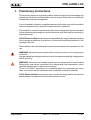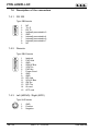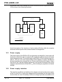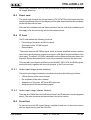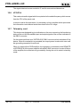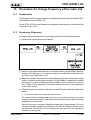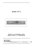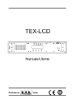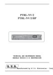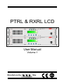
1
PTRL & RXRL LCD
User Manual
Volume 1
Manufactured by
Italy
File name:
CAPITOLI_EN.P65
Version:
1.2
Date:
31/01/2005
Revision History
Date
Version
12/01/04
1.0
02/06/04
1.1
31/01/05
1.2
Reason
New Version
PTRL LCD Rear Panel Upgrade
Added Chapter 11
Editor
J. Berti
J. Berti
J. Berti
PTRL & RXRL LCD - User Manual
Version 1.2
© Copyright 2003-2005
R.V.R. Elettronica SpA
Via del Fonditore 2/2c - 40138 - Bologna (Italia)
Telephone: +39 051 6010506
Fax:
+39 051 6011104
Email:
[email protected]
Web:
www.rvr.it
All rights reserved
Printed and bound in Italy. No part of this manual may be reproduced,
memorized or transmitted in any form or by any means, electronic or
mechanic, including photocopying, recording or by any information
storage and retrieval system, without written permission of the copyright
owner.
Notification of intended purpose and limitations of product use
This product is a FM transmitter intended for FM audio broadcasting. It utilises
operating frequencies not harmonised in the intended countries of use.
The user must obtain a license before using the product in intended country of
use. Ensure respective country licensing requirements are complied with.
Limitations of use can apply in respect of operating freuency, transmitter power
and/or channel spacing.
Declaration of Conformity
Hereby, R.V.R. Elettronica SpA, declares that this FM transmitter is in
compliance with the essential requirements and other relevant provisions of
Directive 1999/5/EC.
PTRL & RXRL LCD
Table of Contents
1.
2.
3.
3.1
3.2
4.
5.
5.1
5.2
5.3
5.4
6.
6.1
6.2
6.3
6.4
7.
7.1
7.2
7.3
7.4
7.5
7.6
8.
8.1
8.2
8.3
8.4
9.
9.1
9.2
9.3
9.4
9.5
9.5
9.6
Preliminary Instructions
Warranty
First Aid
Treatment of electrical shocks
Treatment of electrical Burns
General description
PTRL-LCD quick guide for installation and use
Preparation
Use
Settings and calibration
Software
RXRL-LCD quick guide for installation and use
Preparation
Use
Settings and calibration
Software
External Description
Front Panel of the PTRL LCD
Rear pannel of the PTRL-LCD
Description of the connectors
Front pannel of the RXRL-LCD
Rear pannel of the RXRL-LCD
Description of the connectors
Specifiche Tecniche
Caratteristiche meccaniche
Electrical characteristics of the PTRL LCD
Electrical characteristics of the RXRL-LCD
Electrical characteristics of the PTRL + RXRL-LCD
Functioning principles of the PTRL-LCD
Power supply
Reducing card
Pannel card
Monitoring card
Main card
Power Amplifier
Telemetry card
User Manual
Rev. 1.2 - 31/01/05
1
3
5
5
6
7
9
9
10
10
11
17
17
18
18
19
23
23
24
25
26
27
28
29
29
29
31
32
33
34
34
35
35
35
36
36
i
PTRL & RXRL LCD
10.
10.1
10.2
10.3
10.4
10.5
10.6
10.7
11.
11.1
11.2
ii
Functioning principles of the RXRL-LCD
Power supply
Power supply interface
Panel card
IF Card
Front End
VCO/PLL
Telemetry card
Procedure for change frequency of the radio link
Introduction
Frequency Alignment
Rev. 1.2 - 31/01/05
37
38
38
39
39
39
40
40
41
41
41
User Manual
PTRL & RXRL LCD
1. Preliminary Instructions
This manual is written as a general guide for those having previous knowledge and
experience with this kind of equipment, well conscious of the risks connected with
the operation of electrical equipment.
It is not intended to contain a complete statement of all safety rules which should be
observed by personnel in using this or other electronic equipment.
The installation, use and maintenance of this piece of equipment involve risks both
for the personnel performing them and for the device itself, that shall be used only by
trained personnel.
R.V.R. Elettronica SpA doesn’t assume responsibility for injury or damage resulting
from improper procedures or practices by untrained/unqualified personnel in the
handling of this unit.
Please observe all local codes and fire protection standards in the operations of this
unit.
WARNING: always disconnect power before opening covers or removing any part
of this unit.
Use appropriate grounding procedures to short out capacitors and high voltage points
before servicing.
WARNING: this device can irradiate radio frequency waves, and if it’s not installed
following the instructions contained in the manual and local regulations it could
generate interferences in radio communications.
This is a "CLASS A" equipment. In a residential place this equipment can cause
hash. In this case can be requested to user to take the necessary measures.
R.V.R. Elettronica SpA reserves the right to modify the design and/or the technical
specifications of the product and this manual without notice.
User Manual
Rev. 1.2 - 31/01/05
1 / 44
PTRL & RXRL LCD
This page was intentionally left blank
2 / 44
Rev. 1.2 - 31/01/05
User Manual
PTRL & RXRL LCD
2. Warranty
Any product of R.V.R. Elettronica is covered by a 24 (twenty-four) month warranty.
For components like tubes for power amplifiers, the original manufacturer’s warranty
applies.
R.V.R. Elettronica SpA extends to the original end-user purchaser all manufacturers
warranties which are transferrable and all claims are to be made directly to R.V.R.
per indicated procedures.
Warranty shall not include:
1 Re-shipment of the unit to R.V.R. for repair purposes
2 Any unauthorized repair/modification;
3 Incidental/consequential damages as a result of any defect
4 Nominal non-incidental defects
5 Re-shipment costs or insurance of the unit or replacement units/parts
Any damage to the goods must be reported to the carrier in writing on the shipment
receipt.
Any discrepancy or damage discovered subsequent to delivery, shall be reported to
R.V.R. Elettronica within 5 (five) days from delivery date.
To claim your rights under this warranty, you shold follow this procedure:
1 Contact the dealer or distributor where you purchased the unit. Describe the
problem and, so that a possible easy solution can be detected.
Dealers and Distributors are supplied with all the information about problems
that may occur and usually they can repair the unit quicker than what the
manufacturer could do. Very often installing errors are discovered by dealers.
2 If your dealer cannot help you, contact R.V.R. Elettronica and explain the problem.
If it is decided to return the unit to the factory, R.V.R. Elettronica will mail you
a regular authorization with all the necessary instructions to send back the goods.
3 When you receive the authorization, you can return the unit. Pack
it carefully
for the shipment, preferably using the original packing and seal the package
perfectly. The customer always assumes the risks of loss (i.e., R.V.R. is never
responsible for damage or loss), until the package reaches R.V.R. premises. For
this reason, we suggest you to insure the goods for the whole value. Shipment
must be effected C.I.F. (PREPAID) to the address specified by R.V.R.’s service
manager on the authorization
DO NOT RETURN UNITS WITHOUT OUR AUTHORIZATION AS THEY WILL BE
REFUSED
User Manual
Rev. 1.2 - 31/01/05
3 / 44
PTRL & RXRL LCD
4 Be sure to enclose a written technical report where mention all the problems found
and a copy of your original invoice establishing the starting date of the warranty.
Replacement and warranty parts may be ordered from the following address. Be
sure to include the equipment model and serial number as well as part description
and part number.
R.V.R. Elettronica SpA
Via del Fonditore, 2/2c
40138 BOLOGNA
ITALY
Tel. +39 051 6010506
4 / 44
Rev. 1.2 - 31/01/05
User Manual
PTRL & RXRL LCD
3. First Aid
The personnel employed in the installation, use and maintenance of the device, shall
be familiar with theory and practice of first aid..
3.1
3.1.1
Treatment of electrical shocks
If the victim is not responsive
Follow the A-B-C's of basic life support
•
Place victim flat on his backon a hard surface.
•
Open airway: lift up neck, push forehead back (Fig. 3-1).
•
clear out mouth if necessary and observe for breathing
•
if not breathing, begin artificial breathing (Figure 3-2): tilt head, pinch nostrils,
make airtight seal, four quick full breaths. Remember mouth to mouth resuscitation
must be commenced as soon as possible
Figure 3-1
•
Figure 3-2
Check carotid pulse (Fig 3-3); if pulse is absent, begin artificial circulation
(Fig. 3-4) depressing sternum (Fig. 3-5)
Figure 3-3
Figure 3-4
Figure 3-5
•
In case of only one rescuer, 15 compressions alternated to two breaths.
•
If there are two rescuers, the rythm shall be of one brath each 5 compressions.
•
Do not interrupt the rythm of compressions when the second person is giving
breath.
•
Call for medical assistance as soon as possible.
User Manual
Rev. 1.2 - 31/01/05
5 / 44
PTRL & RXRL LCD
3.1.2
3.2
3.2.1
If victim is responsive
•
Keep them warm
•
Keep them as quiet as possible
•
Loosen their clothing (a reclining position is recommended)
•
Call for medical help as soon as possible
Treatment of electrical Burns
Extensive burned and broken skin
•
Cover area with clean sheet or cloth
•
Do not break blisters, remove tissue, remove adhered particles of
apply any salve or ointment.
•
Treat victim for shock as required.
•
Arrange transportation to a hospital as quickly as possible.
•
If arms or legs are affected keep them elevated
clothing, or
If medical help will not be available within an hour and the victim is conscious and not
vomiting, give him a weak solution of salt and soda: 1 level teaspoonful of salt and 1/
2 level teaspoonful of baking soda to each quart of water (neither hot or cold). Allow
victim to sip slowly about 4 ounces (half a glass) over a period of 15 minutes.
Discontinue fluid if vomiting occurs
DO NOT give alcohol
3.2.2
6 / 44
Less severe burns
•
Apply cool (not ice cold) compresses using the cleansed available cloth article.
•
Do not break blisters, remove tissue, remove adhered particles of clothing, or
apply salve or ointment.
•
Apply clean dry dressing if necessary.
•
Treat victim for shock as required.
•
Arrange transportation to a hospital as quickly as possible
•
If arms or legs are affected keep them elevated.
Rev. 1.2 - 31/01/05
User Manual
PTRL & RXRL LCD
4. General description
The PTRL-LCD and the RXRL-LCD are, respectively a broadband radio transmitter
and receiver for the transport of audio signals as an auxiliary to the frequency
modulation sound broadcasting.
This type of equipment is often called STL (Studio-to-Transmitter Link).
The PTRL-LCD is designed to work in an optimum way when connected to the
receiver RXRL-LCD.
Externally, it is a box to mount in a 19" rack, each one being 2HE high.
The standard working frequency bands are the following:
•
220 MHz ÷ 240 MHz (5KHz steps)
•
420 MHz ÷ 440 MHz (5KHz steps)
•
900 MHz ÷ 960 MHz (5KHz steps)
The working frequency (and therefore the band) should be indicated when the order
for such product is placed.
WARNING: upon request, these links are available at other frequency bands and
steps, please contactact RVR in order to check the availability of modules at the
required frequency.
The PTRL-LCD is available with internal stereo coder which can guarantee an
optimum stereophonic separation as well as a low level of armonic distorsion. In
function of your own requirements it can be configurated for the functioning under the
Mono/MPX mode (that is to say when excluding the stereo coder and when using the
"left" inputs as a "mono" input and the BNC, which is always on, as "MPX"). The
configuration can be done by the user with the help of microswitches which can be
selected from the outside. It has also two inputs (SCA1 and SCA2) for signals which
are modulated on sub-carriers by appropriated external coders, normally used in
Europe for the RDS transmission (Radio Data System).
In the standard version of the RXRL-LCD, the demodulated signal is available in the
MPX form (that is to say the complete basis signal band) and in the mono version.
Moreover there are two connectors used for the respective SCA outputs. As an option,
the RXRL-LCD can be equipped with a stereo decoder option. Also when this option
is present, apart from the outputs for the LEFT and RIGHT channels, the outputs for
the MPX signal are present and for the possible sub-carriers.
The important audio characteristics of this equipment are the low distorsion and
intermodulation values and the high S/N level; another important quality both of the
PTRL-LCD and the RXRL-LCD is its very simple construction and its easy use.
User Manual
Rev. 1.2 - 31/01/05
7 / 44
PTRL & RXRL LCD
Both the PTRL-LCD and the RXRL-LCD were designed in a modular way: the different
functions are executed by modules connected directly with male and female
connectors or with flat cables with connectors at both ends. This type of design makes
the maintenance and the possible replacement of modules an easy operation.
The microprocessor system includes an LCD display and series of push-buttons
that enable the interaction with the user, and implements the following functionsfor
the transmitter:
•
Setting of the output power
•
Setting of the working frequency
•
Activation and switch off of the power distribution
•
Measurement and display of the working parameters of the transmitter
•
Communication with external devices
These functions are implemented for the receiver:
•
Display of the modulation
•
Setting of the working frequency
•
Setting of the muting
•
Measurement and display of the working parameters of the receiver
•
Communication with external devices
The system of the management software is composed of several menus.
The user can navigate between the different submenus by using four push-buttons:
ESC, LEFT/HIGH, RIGHT/LOW, and ENTER.
The status of the unit is indicated by four LEDs which are present on the front pannel:
•
ON, LOCK, FOLDBACK, RF MUTE for the PTRL LCD.
•
ON, LOCK, PILOT, MUTE for the RXRL LCD.
Both the transmitter and the receiver have an input for the external 24 Vcc supply.
This auxiliary supply source, that can be realized by the user with the help of rescuebatteries, is automatically used in case of AC voltage absence.
8 / 44
Rev. 1.2 - 31/01/05
User Manual
PTRL & RXRL LCD
5. PTRL-LCD quick guide for installation and use
This chapter contains the necessary instructions for the installation and use of the
equipment. In case some aspects are not totally clear, for instance when a user is
using this equipment for the first time, we advise the new user to read carefully the
entire description contained in this manual.
5.1
Preparation
Unpack the transmitter and check, before making any operation, that the unit has not
suffered from any mishandling during transport. In particular check that all the
connectors are in perfect conditions.
Check that the supply voltage value coincides with the AC voltage available.
The input supply field is of:
•
PTRL LCD
90-260 VAC
Check that the switches of the PTRL-LCD are in the position "0" (off).
The PTRL-LCD has 2 switches: one is included in the VDE socket for the AC supply
cable and interrupts completely the AC supply of the unit, while the second is situated
on the front pannel and his action is to inhibit the switching power supply of the unit.
Connect the RF output of the exciter to the antenna cable or to a dummy load adapted
for the working frequency and the power output used.
Connect the AC cable to the corresponding VDE socket.
REMARK: It is essential that the AC network has an accurrate grounding system in
order to ensure both the safety of the users and the correct functioning of the unit.
If the user intends to use external batteries in case of AC supply interruption, connect
them to the clamps situated at the back of the equipment being careful to respect the
polarity.
WARNING: Keep in mind that the general switch of the transmitter has an effect on
the AC supply, and not on the possible auxiliary supply. If you use an external supply
with continuous current, it is then necessary to have an external switch for this purpose.
Connect the audio cables of your own audio signal to the apropriate connectors
situated at the back of the exciter.
User Manual
Rev. 1.2 - 31/01/05
9 / 44
PTRL & RXRL LCD
5.2
Use
Switch on the transmitter by putting the selector on the position "I" (on) the switch
situated on the pannel, and switch it on thanks to the switch situated on the front
pannel.
Enter the menu "Set" and set the working frequency desired. For the description of
the different menus, read the chapter 5.4.
With the help of the switches and trimmers situated on the rear pannel, set the
characteristics (impedance, preenphasis, and possibly stereo/mono) and the levels
of the audio inputs and RDS (if used).
REMARK: When it comes out of the factory, the output power of the unit is regulated
at the minimum and is setted on the OFF position. Anyway we always advise to
check the setted level before you select the output power, especially when the unit is
used as modulator of a power amplifier.
From the predefined menu, set the desired power level.
From the menu "Fnc", set the power output.
5.3
Settings and calibration
The only regulations that should be done manually on the PTRL-LCD are the
regulations of the levels and audio functioning modes.
On the rear pannel of the unit there is a trimmer for each input of the exciter; the silkscrenn of the pannel indicated to which input each trimmer refers to. The sensitivity
of the different inputs can be regulated with the trimmers as indicated in the following
tables:
•
Sensitivity of the inputs
Input
MPX/RDS
Chap. 7.2
[10]
Trimmer
[11]
Sensitivity
-20 ÷ +13 dBm
SCA1
SCA2
Left Mono/MPX
Right/Mono
[9]
[22]
[26]
[24]
[23]
[25]
- 8 ÷ +13 dBm
- 8 ÷ +13 dBm
-13 ÷ +13 dBm
[13]
[12]
-13 ÷ +13 dBm
Notes
Input level for 2.0 kHz (-30 dB) of
deviation
Input level for 7.5 kHz (-20 dB) of
deviation
Input level for75 kHz(0 dB) of deviation
In order to regulate the sensitivity level of the inputs, it is important to keep in mind
that the instantaneous modulation level is indicated in the predefined menu and that
an indicator indicates that the level is at 75 kHz. For a correct regulation, we advise
to bring a signal equivalent to the signal level of your own audio programme into the
input of the unit and regulate the corresponding trimmer until the instantaneous
deviation coincides with the 75 kHz indication.
10 / 44
Rev. 1.2 - 31/01/05
User Manual
PTRL & RXRL LCD
For the regulation of the levels of the sub-carriers' inputs, a similar procedure can be
followed, with the help of the option "X10" which can be selected from the menu Fnc.
With this option, the indicated modulation level is multiplied per the factor 10, so that
the hachured indication of the predefined menu coincides with a deviation value of
7,5 kHz.
As for the stereo version, there is an appropriate menu in which the levels of the right
and left channels with the corresponding nominal level indicators for the maximum
75Khz deviation are indicated separately.
The position of the DIP switches that are needed to select the available options is
indicated on the silk-screen.
Preenphasis (switch [7] Chap. 7.2):
•
ON
1
ON
2
•
3
4
50 µs
1
2
3
4
75 µs
Impedance of L&R inputs (XLR type) (switch [27] Chap. 7.2):
Switch 1: Impedance of R XLR ON input = 600 Ω, OFF = 10 kΩ
Switch 2: Impedance of L XLR ON input = 600 Ω, OFF = 10 kΩ
•
Functioning modes / Impedance of MPX input ([8] Chap. 7.2):
Switch 1: Functioning mode ON = Mono, OFF = Stereo
Switch 2: impedance of MPX ON input = 50 Ω, OFF = 10 kΩ
5.4
Software
The unit is equipped with an LCD display with 2 lines on which several menus are
shown. A general view of the menus of the unit are shown in the illustration.
On the left side of the display, depending on the case, one of the following symbols
can be present:
The parameter indicated by the arrow can be modified
The arrow indicates the current line, whose parameter cannot be modified. This
symbol is present in the menus composed of several lines as an help for the
scrolling of the menus.
When the unit is switched on, the LCD display shows the predefined view, with the
graphical representation of the instantaneous modulation level and the indication of
the value of the direct power erogated:
User Manual
Rev. 1.2 - 31/01/05
11 / 44
PTRL & RXRL LCD
The vertical bars near the title "Mod" indicate the progress of the modulation in real
time; the hachured bar indicates the maximum 75 kHz nominal modulation level
(100%).
In order to change the power level setted, select with the push-button GIU' the line
which corresponds to the power and keep the ENTER button pressed until you enter
the modify mode.
The above line displays the instantaneous power reading (in this example 10W),
while the bar indicates the setted level. In order to increase the level, keep the
DESTRA/GIU' button pressed, in order to reduce it press the SINISTRA/SU' button.
As the setted level increases or decreases, the bar gets longer or shorter in order to
enable the display of the current setting. Once the desired level is reached, press
ENTER to confirm and exit the predefined menu. Please note that the setted value is
anyway memorized, therefore when you press ESC or when the timeout period is
passed and no button was pressed, the power will remain on the last setted level.
When you press twice on the ESC button while you are in the predefined menu, the
following selection view is displayed, and from this view it will be then possible to
enter to all the other menus:
To enter one of the submenus, select the name (that will be enhanced by a flashing
cursor) with the RIGHT or LEFT push-buttons and then press the ENTER button.
If on the contrary, you wish to return to the predefined menu, you just have to press
again the ESC push-button.
In some cases, on the left side of the menu an arrow can appear. It means that it is
necessary to indicate the current line selected. When the arrow is full, the parameter
can be modified, while when it is empty, the parameter can only be viewed.
REMARK: The "L&R" menu is available only in the stereo version. In the mono version
the "L&R" inscription do not appear.
5.4.1
Functioning menu (Fnc)
From this menu the user can set the deviation display mode, he can switch on or
inhibit the power erogation of the transmitter and he can modify the attention threshold.
12 / 44
Rev. 1.2 - 31/01/05
User Manual
PTRL & RXRL LCD
In order to intervene on one of the three keys, select the corresponding line with the
"UP" and "DOWN" buttons and then press and keep the ENTER button pressed until
the order is accepted. In this way the Pwr setting will go from On to Off or viceversa
and the Mod setting will go from "X1" to "X10" or viceversa.
In "X10" mode the indication of the instantaneous deviation is multiplied by 10, this is
why the hachured indicator on the predefined menu coincides with the 7,5 kHz value
instead of 75 kHz. This visualization mode is useful when the user wants to have low
deviation levels displayed, for instance when they are provoked by the pilot tone or
the subcarriers.
As indicated in the introduction, the transmitter offers the possibiliy to the user to set
the attention threshold. This latter is compared to the level of one of the functioning
parameters of the unit. The result of the comparison is available on the telemetry
connector, and can be read on the display as "O" (which means open, that is to say
the result is wrong) or "C" (which means closes, therefore the result is true).
The threshold that can be setted (Power Good) refers to the transmitted power level.
The threshold is expressed in percentage of the full scale of the considered size.
The full-scale of the monitored size of the attention threshold for the PTRL-LCD is:
•
Forward Power
10 W
In order to change the values of the attention thresholds, the following procedure
should be followed:
•
Select the line that should be modified (with the 'UP' and 'DOWN' buttons)
•
Press the ENTER button
•
Modify the value of the threshold ('UP' and 'DOWN' buttons)
•
Press the ENTER button
In this example, the alarm threshold is:
•
5.4.2
PwG
9W
(90% x 10 W)
Pwr menu (Pwr)
This view shows to the user the measurements corresponding to the power erogation
of the exciter:
•
Forward Power (Fwd )
•
Reflected Power (Rfl)
User Manual
Rev. 1.2 - 31/01/05
13 / 44
PTRL & RXRL LCD
The values indicated are "readings", and therefore cannot be modified (remark the
empty triangle). In order to modify the power setting, use the predefined menu as
described formerly.
5.4.3
Power Amplifier menu (P.A)
This view, composed of three lines that can be scrolled with the 'UP' and 'DOWN'
buttons, shows to the user the values corresponding to the power amplifier of the
unit:
5.4.4
•
Voltage (VPA)
•
Absorbed current (IPA)
Menù Impostazioni (Set)
This menu enables to read and set the working frequencies.
When you press the ENTER button, it will be possible to modify the setted frequency
with the 'UP' (the frequency increases) and 'DOWN' (the frequency decreases).
After a new frequency value was setted, press the ENTER button to confirm the choice;
the exciter will unlock from the current frequency (the LED LOCK switches off) and
will lock to the new working frequency (the LOCK LED lits up). On the contrary when
you press ESC or when you let the timeout passes by, the frequency will remain
setted at the last value memorized.
5.4.5
Mix menu (Mix)
This menu enables to set the path of the unit on a serial bus connection of the type
I2C:
The I2C AC path is important when the exciter is connected to an RVR transmission
system which allows the use of this protocol. We recommend not to modify it with no
reason.
14 / 44
Rev. 1.2 - 31/01/05
User Manual
PTRL & RXRL LCD
5.4.6
Versions Menu (Vrs)
zThis view shows the version of the unit and the date to the software release.
5.4.7
Channels menu (L&R)
This menu works on stereo version units.
The input levels of the right and left channels are represented by vertical bars as
indicated in the following illustration.
The hachured bar indicates the level which corresponds to the global deviation of
100% of the channels.
User Manual
Rev. 1.2 - 31/01/05
15 / 44
PTRL & RXRL LCD
Pagina lasciata intenzionalmente in bianco
16 / 44
Rev. 1.2 - 31/01/05
User Manual
PTRL & RXRL LCD
6. RXRL-LCD quick guide for installation and use
This chapter contains the necessary instructions for the installation and use of the
equipment. In case some aspects are not totally clear, for instance when a user is
using this equipment for the first time, we advise the new user to read carefully the
entire description contained in this manual.
6.1
Preparation
Unpack the transmitter and check, before making any operation, that the unit has not
suffered from any mishandling during transport. In particular check that all the
connectors are in perfect conditions.
Check that the supply voltage value coincides with the AC voltage available.
The input supply field is of:
•
RXRL LCD
85-264 VAC
Check that the switches of the RXRL-LCD are in the position "0" (off).
The RXRL-LCD has a switch which interrupts completely the AC supply of the unit.
Connect the RF output of the exciter to the antenna cable .
Connect the AC cable to the corresponding VDE socket.
REMARK: It is essential that the AC network has an accurrate grounding system in
order to ensure both the safety of the users and the correct functioning of the unit.
If the user intends to use external batteries in case of AC supply interruption, connect
them to the clamps situated at the back of the equipment being careful to respect the
polarity.
WARNING: Keep in mind that the general switch of the transmitter has an effect on
the AC supply, and not on the possible auxiliary supply. If you use an external supply
with continuous current, it is then necessary to have an external switch for this purpose.
Connect the audio cables of your own audio signal to the apropriate connectors
situated at the back of the exciter
User Manual
Rev. 1.2 - 31/01/05
17 / 44
PTRL & RXRL LCD
6.2
Use
Switch on the receiver by putting the selector on the position "I" (on) the switch situated
on the rear pannel.
Enter the menu "Set" and set the working frequency desired. For the description of
the different menus, read the chapter 6.4.
With the help of the switches and trimmers situated on the rear pannel, set the
characteristics (deenphasis) and the levels of the audio outputs.
From the predefined menu, set the desired power level.
From the menu "Fnc", set the power output
6.3
Settings and calibration
The only regulations that should be done manually on the RXRL-LCD are the
regulations of the levels and audio functioning modes.
On the rear pannel of the unit there is a trimmer for each output of the receiver. The
sensitivity of the different outputs can be regulated with the trimmers as indicated in
the following tables:
•
Sensitivity of the inputs
Output
MPX
Chap. 7.5
[13]
Trimmer
[14]
Sensitivity
-20 ÷ +13 dBm
SCA
SCA/MPX
Left Mono/MPX
Right/Mono
[5]
[4]
[17]
[6]
[15]
[16]
- 8 ÷ +13 dBm
- 8 ÷ +13 dBm
-10 ÷ +14 dBm
[8]
[7]
-10 ÷ +14 dBm
Notes
Output level for 2.0 kHz (-30 dB) of
deviation
Output level for 7.5 kHz (-20 dB) of
deviation
Output level for 75 kHz(0 dB) of
deviation
In order to regulate the sensitivity level of the inputs, it is important to keep in mind
that the instantaneous modulation level is indicated in the predefined menu and that
an indicator indicates that the level is at 75 kHz. For a correct regulation, we advise
to bring a signal equivalent to the signal level of your own audio programme into the
input of the unit and regulate the corresponding trimmer until the instantaneous
deviation coincides with the 75 kHz indication.
For the regulation of the levels of the sub-carriers' outputs, a similar procedure can
be followed, with the help of the option "X10" which can be selected from the menu
Fnc. With this option, the indicated modulation level is multiplied per the factor 10, so
that the hachured indication of the predefined menu coincides with a deviation value
of 7,5Khz.
18 / 44
Rev. 1.2 - 31/01/05
User Manual
PTRL & RXRL LCD
As for the stereo version, there is an appropriate menu in which the levels of the of
the right and left channels with the corresponding nominal level indicators for the
maximum 75Khz deviation are indicated separately.
The position of the DIP switches that are needed to select the available options is
indicated on the silk-screen.
•
Deenphasis (switch [18] Chap. 7.5):
50 µs
6.4
75 µs
Software
The unit is equipped with an LCD display with 2 lines on which several menus are
shown. A general view of the menus of the unit are shown in the illustration.
On the left side of the display, in function of the cases, one of the following symbols
can be present:
The parameter indicated by the arrow can be modified
The arrow indicates the current line, whose parameter cannot be modified. This
symbol is present in the menus composed of several lines as an help for the
scrolling of the menus.
When the unit is switched on, the LCD display shows the predefined view, with the
graphical representation of the instantaneous modulation level and the indication of
the value of the direct power erogated:
The vertical bars under the key "Mod" indicate the progress of the modulation in real
time; the hachured bar indicates the maximum 75 kHz nominal modulation level
(100%).
The above line displays the instantaneous reading of the signal level received on
analog scale, while the bar indicates the setted level. In order to increase the level,
keep the RIGHT/DOWN button pressed, in order to reduce it press the LEFT/UP
button. As the setted level increases or decreases, the bar gets longer or shorter in
order to enable the display of the current setting. Once the desired level is reached,
press ENTER to confirm and exit the predefined menu. Please note that the setted
value is anyway memorized, therefore when you press ESC or when the timeout
period is passed and no button was pressed, the power will remain on the last setted
level.
User Manual
Rev. 1.2 - 31/01/05
19 / 44
PTRL & RXRL LCD
When you press twice on the ESC button while you are in the predefined menu, the
following selection view is displayed, and from this view it will be then possible to
enter to all the other menus:
To enter one of the submenus, select the name (that will be enhanced by a flashing
cursor) with the RIGHT or LEFT push-buttons and then press the ENTER button.
If on the contrary, you wish to return to the predefined menu, you just have to press
again the ESC push-button.
In some cases, on the left side of the menu an arrow can appear. It indicates that it is
necessary to indicate the current line selected. When the arrow is full, the parameter
can be modified, while when it is empty, the parameter can only be viewed.
6.4.1
Functioning menu (Fnc)
From this menu the user can set the deviation display mode, he can switch on or
inhibit the muting mode.
In order to intervene on one of the three keys, select the corresponding line with the
"UP" and "DOWN" buttons and then press and keep the ENTER button pressed until
the order is accepted. In this way the Pwr setting will go from On to Off or viceversa
and the Mod setting will go from "X1" to "X10" or viceversa.
In "X10" mode the indication of the instantaneous deviation is multiplied by 10, this is
why the hachured indicator on the predefined menu coincides with the 7,5 kHz value
instead of 75 kHz. This visualization mode is useful when the user wants to have low
deviation levels displayed, for instance when they are provoked by the pilot tone or
the subcarriers.
As indicated in the introduction, the transmitter offers the possibiliy to the user to set
the muting mode. "MUTE OFF" indicates that the muting was not activated, therefore
the received signal is situated at the audio outputs. "MUTE ON" indicates that the
muting is activated, therefore the audio outputs are muted.
20 / 44
Rev. 1.2 - 31/01/05
User Manual
PTRL & RXRL LCD
6.4.2
Set menu (Set)
This menu enables to read and set the working frequencies .
When you press the ENTER button, it will be possible to modify the setted frequency
with the 'UP' (the frequency increases) and 'DOWN' (the frequency decreases).
After a new frequency value was setted, press the ENTER button to confirm the choice;
the exciter will unlock from the current frequency (the LED LOCK switches off) and
will lock to the new working frequency (the LOCK LED lits up). On the contrary when
you press ESC or when you let the timeout passes by, the frequency will remain
setted at the last value memorized.
6.4.3
Aud menu (Aud)
The levels of the inputs of the left and right channels are represented by vertical bars
as indicated in the following illustration.
The hachured bar indicates the level which corresponds to the global deviation of
100% of the channels.
6.4.4
Mix menu (Mix)
This menu enables to set the path of the unit on a serial bus connection of the type
I2C:
The I2C AC path is important when the exciter is connected to an RVR transmission
system which allows the use of this protocol. We recommend not to modify it with no
reason.
User Manual
Rev. 1.2 - 31/01/05
21 / 44
PTRL & RXRL LCD
6.4.5
Versions menu (Vrs)
This view shows the version of the unit and the date to the software release.
22 / 44
Rev. 1.2 - 31/01/05
User Manual
PTRL & RXRL LCD
7. External Description
This chapter describes the elements which are present on the front and rear pannel
of the PTRL-LCD and the RXRL-LCD.
7.1
Front Panel of the PTRL LCD
Figure 7.1
[1] AIR FLOW
[2] ON
[3] LOCK
[4] FOLDBACK
[5] R.F. MUTE
[6] CONTRAST
[7] ESC
[8] SINISTRA/SU’
[9] DESTRA/GIU’
[10] ENTER
[11] DISPLAY
[12] POWER
User Manual
Grid for the air flow
Green LED, illuminato when the transmitter is feeded
If it is on, indicates that the PLL is locked at the reference
frequency
yellow LED, if it is flashing, it indicates the intervention of the
foldback function (automatic reduction of the erogated power)
If it is flashing, it indicates that the exciter is not erogating power
because it is inhibitted by an external interlock
Regulation Trimmer of the contrast of the display
Push-button to press to exit from a menu
Push-button for the navigation in the system composed of several
menus and for the modification of the parameters
Push-button for the navigation in the system composed of several
menus and for the modification of the parameters
Push-button for the confirmation of a parameter and to enter the
menus
Liquid crystal display
ON/OFF switch. It switches off the exciter without disconnecting
the AC supply
Rev. 1.2 - 31/01/05
23 / 44
PTRL & RXRL LCD
7.2
Rear pannel of the PTRL-LCD
Figure 7.2
[1] P.A BLOCK
[2] R.F. OUTPUT
[3] INTERLOCK
[4] FWD EXT. AGC
[5] RFL EXT. AGC
[6] PHASE ADJ
[7] PREENPHASIS
[8] MODE/MPX IMP
[9]
[10]
[11]
[12]
[13]
[14]
[15]
SCA 1
MPX/RDS
MPX/RDS ADJ
RIGHT/MONO ADJ
RIGHT/MONO
PLUG
24VDC IN
[16]
[17]
[18]
[19]
[20]
FAN
R.F. TEST POINT
REMOTE
EXT REF 10MHz
RS232
[21] 19 KHZ PILOT
[22]
[23]
[24]
[25]
[26]
[27]
24 / 44
SCA 2
SCA2 ADJ
SCA1 ADJ
LEFT-MONO/MPX ADJ
LEFT-MONO/MPX
IMPEDANCE
Fuse-holder. Contains the protection fuse for the 3,15 A.power
supply
RF Output connector N type, 50Ω.
BNC interlock connector: When the main conductor is grounded,
the transmitter is forced to go in stand-by mode.
Trimmer for the control of the erogated power in function of the
FWD Fold input
Trimmer for the control of the erogated power in function of the
RFL Fold input
Trimmer for the regulation of the pilot tone phase.
Dip-switch for the setting of the preenphasis 50 or 75 µs. The
preenphasis has an influence on the right and left inputs in stereo
and on the mono input. The MPX inputs are not influenced by the
setting of the preenphasis.
Dip-switch for the selection both of the transmission mode
(STEREO or MONO) and the impedance of the MPX input MPX,
selectable at 50Ω or 10kΩ.
BNC connector of the unbalanced SCA1 input.
BNC connector of the unbalanced MPX input.
Trimmer for the regulation of the levels of the MPX input.
Trimmer for the regulation of the levels of the Right input.
XLR connector for the input of the Right audio channel.
AC voltage plug, 90-260V 50-60Hz.
Connectors for the external 24V supply . Positive (red)
or negative (black).
Blower for the forced cooling.
-30dB output at the output power level.
DB15 connector for the telemetry of the device.
Not used (reserved for future applications)
DB9 connector for the interface with other equipment and
programmation made by the factory.
BNC output connector for the pilot tone, which can be used for
the synchronisation of the external devices such as RDS coder,
etc…
BNC connector for the SCA2 input
Trimmer for the regulation of the SCA2 input levels.
Trimmer for the regulation of the SCA1 input levels.
Trimmer for the regulation of the LEFT-MONO input levels.
XLR connector for the LEFT-MONO audio channel input.
Dip-switch for the selection of the impedance of the balanced
audio inputs, selectable at 600Ω or 10kΩ.
Rev. 1.2 - 31/01/05
User Manual
PTRL & RXRL LCD
7.3
7.3.1
Description of the connectors
RS 232
Type: DB9 female
1
7.3.2
6
1
2
3
4
5
6
7
8
9
NC
TX_D
RX_D
Internally connected to 6
GND
Internally connected to 4
Internally connected to 8
Internally connected to 7
NC
Remote
Type: DB15 female
1
7.3.3
9
1
2
3
4
5
6
7
8
9
10
11
12
13
14
15
Interlock
FWD fold
GND
SDA IIC Bus
VPA Tlm
FWD tlm
Power Good
GND
GND
RFL fold
SCL IIC Bus
IPA Tlm
RFL Tlm
On cmd
OFF cmd
Left (MONO) / Right (MPX)
Type: XLR female
2
1
3
User Manual
1
2
3
GND
Positive
Negative
Rev. 1.2 - 31/01/05
25 / 44
PTRL & RXRL LCD
7.4
Front pannel of the RXRL-LCD
Figure 7.4
[1] AIR FLOW
[2] ON
[3] LOCK
[4] PILOT
[5] MUTE
[6] CONTRAST
[7] ESC
[8] SINISTRA/SU’
[9] DESTRA/GIU’
[10] ENTER
[11] DISPLAY
[12] POWER
26 / 44
Grid for the air flow
Green LED, illuminato when the transmitter is feeded
If it is on, indicates that the VCO is locked at the reference
frequency
yellow LED, if it is flashing, it indicates that there is a disfunction
in the demodulated signal.
yellow LED, if it is flashing, it indicates that the muting is
activated, which means that the input signal has decreased under
the defined threshold
Regulation Trimmer of the contrast of the display
Push-button to press to exit from a menu
Push-button for the navigation in the system composed of several
menus and for the modification of the parameters
Push-button for the navigation in the system composed of several
menus and for the modification of the parameters
Push-button for the confirmation of a parameter and to enter the
menus
Liquid crystal display
ON/OFF switch. It switches off the exciter without disconnecting
the AC supply
Rev. 1.2 - 31/01/05
User Manual
PTRL & RXRL LCD
7.5
Rear pannel of the RXRL-LCD
Figure 7.4
[1] MAINS VOLTAGE
[2] R.F. INPUT 50 Ω
[3] MUTE
[4]
[5]
[6]
[7]
[8]
[9]
SCA/MPX OUT
SCA OUT
SCA OUT ADJ
RIGHT/MONO ADJ
MONO/RIGHT
24VDC IN
[10] REMOTE
[11] RS232
[12]
[13]
[14]
[15]
[16]
[17]
[18]
User Manual
10.7 MHz IF OUT
MPX OUT
MPX OUT ADJ
SCA/MPX OUT ADJ
MONO/LEFT ADJ
MONO/LEFT
DEENPHASIS
Plug for the AC voltage, 85-264V 50-60Hz.
RF input connector N type, 50Ω.
BNC interlock connector for the muting of the audio outputs with
an external command.
BNC connector for the unbalanced SCA or MPX output.
BNC connector, for the unbalanced SCA OUT output.
Trimmer for the regulation of the SCA OUT output.
Trimmer for the regulation of the RIGHT/MONO output levels.
XLR connector for the audio channel Mono or Right output.
Connectors for the external 24V power supply. Positive (red)
and negative (black).
DB15 connector for the telemetry of the device.
DB9 connector for the interface with other devices and for the
programmation made by the factory.
BNC output connector for the 10.7 MHz sampling for tests.
BNC output connector for the unbalanced MPX.
Trimmer for the regulation of the MPX OUT input levels.
Trimmer for the regulation of the SCA/MPX input levels.
Trimmer for the regulation of the MONO/LEFT input levels.
XLR connectors for the MONO or LEFT audio channel input.
Dip-switch for the setting of the deenphasis 50 or 75 ms. The
deenphasis has an influence on the right and left outputs in
stereo mode and on the mono input. The MPX outputs are not
influenced by the setting of the preenphasis.
Rev. 1.2 - 31/01/05
27 / 44
PTRL & RXRL LCD
7.6
7.6.1
Description of the connectors
RS 232
Type: DB9 female
1
7.6.2
6
1
2
3
4
5
6
7
8
9
NC
TX_D
RX_D
Internally connected to 6
GND
Internally connected to 4
Internally connected to 8
Internally connected to 7
NC
Remote
Type: DB15 female
1
7.6.3
9
1
2
3
4
5
6
7
8
9
10
11
12
13
14
15
Interlock
FWD fold
GND
SDA IIC Bus
VPA Tlm
FWD tlm
Power Good
GND
GND
RFL fold
SCL IIC Bus
IPA Tlm
RFL Tlm
On cmd
OFF cmd
Left (MONO) / Right (MPX)
Type: XLR female
2
3
28 / 44
1
1
2
3
GND
Positive
Negative
Rev. 1.2 - 31/01/05
User Manual
PTRL & RXRL LCD
8. Specifiche Tecniche
8.1
Caratteristiche meccaniche
Dimensions of the panel
Depth
Weight
Working temperature
8.2
483 mm (19”) x 88 mm (3 1/2”) (2 HE)
344 mm (26 1/2”)
About 6 Kg
-10 °C ÷ 50 °C
Electrical characteristics of the PTRL LCD
General
RFoutput power
RF output connector
RF output impedance
Frequency band
0-10 W continuously selectable
Type "N"
50 Ohm
220 ÷ 240 MHz
420 ÷ 440 MHz
900 ÷ 960 MHz
(Other frequency bands are available unpon
request, please contact RVR to know the
availability of modules for the required
frequency)
Programmation of the frequency
Direct through software
Frequency stability
±1ppm from -10°C to 50°C
Type of modulation
Direct modulation of the carrier
Supression of the spuries and harmonics Respect or exceed the FCC & CCIR (typical 75 dB)
Ability of modulation
Respect or exceed the FCC & CCIR (typical
240khz MPX or Mono, 210 KHz Stereo)
Asynchronous modulation AM residual
-70 dB or inferior against 100% AM, without
deenphasis
Synchronous modulation AM residual
≅ -50 dB or inferior against 100% AM, FM
modulation 75 kHz at 400Hz, without
deenphasis
Transitory intermodulation distorsion
< 0.1% (typical 0.05%)measured with square
wave at 3.18 kHz and sinusoidal at 15 kHz
with a 75 kHz FM
A.C. supply
≅ 80 V ÷ 260 V, full-range
C.C. supply
24 V
Consumption
120 VA ca.
Inputs
Left-Mono/MPX input
Right/Mono input
MPX/RDS input
Input Impedance
Input Level
Preemphasis
User Manual
XLR female type
balanced or unbalanced
XLR female type
balanced or unbalanced
BNC type
unbalanced
10 kOhm or 600 Ohm, selectable through
DIP-switch
-20 dBm ÷ +13 dBm , continuous fine
regulation by trimmer
Selectable:
0
50 us (CCIR)
75 us (FCC)
Rev. 1.2 - 31/01/05
29 / 44
PTRL & RXRL LCD
SCA1 and SCA2 inputs
2 connectors BNC type unbalanced
IImpedance of the SCA1 and SCA2 inputs 10 kOhm
Level of the SCA1 and SCA2 inputs
-20 dBm ÷ +13 dBm for a 2,0 kHz deviation
adjustable by trimmer
Outputs
RF Out:
standard connector "N" type with impedance
50 Ohm
BNC connector approx. level -30 dB against
the RF output, impedance 50 Ohm
1 Vpp minimum load 4.7 kOhm
RF Test
Tono pilota 19 KHz
MONO Functioning
S/N FM (200 MHz)
S/N FM (400 MHz)
S/N FM (900 MHz)
Amplitude response /frequency
Total armonics distorsion (THD)
> 80dB against a 75KHz deviation with a 50
us deenphasis, detector RMS at 400 Hz
> 75dB against a 75KHz deviation with
deenphasis 50 us, detector RMS at 400MHz
> 80dB against a 75KHz deviation with a 50
us deenphasis, detector RMS at 400 Hz
± 0.3 dB, 40 Hz ÷ 15 KHz
≤ 0.08%
MPX Functioning
Composite FM S/N
> against 75KHz measured in the 40 Hz ¸ 75
KHz band with deenphasis 50 us, detector
RMS
Amplitude response /MPX frequency MPX ± 0.3 dB, 40 Hz ÷ 75 KHz
Armonic distorsion total MPX
≤ 0.08 %
Stereo Functioning
S/N FM (200 MHz)
S/N FM (400 MHz)
S/N FM (900 MHz)
Amplitude response /Audio frequency
Total armonics distorsion
> 73dB against a 75KHz deviation with a
deenphasis 50 us, detector RMS at 400 Hz
> 70dB against a 75KHz deviation with
deenphasis 50 us, detector RMS at 400MHz
> 67dB against a 75KHz deviation with 50 us
deenphasis, detector RMS at 400 Hz
± 0.3 dB, 40 Hz ÷ 15 KHz
≤ 0.08 %
Remote Connections
Interlock connector
Serial Interface
Telemetry connector
30 / 44
BNC type, inhibits the power erogation when
it is short-circuited
Female DB9 RS232
Type female DB15, provides indications on
the status of the unit
Rev. 1.2 - 31/01/05
User Manual
PTRL & RXRL LCD
8.3 Electrical characteristics of the RXRL-LCD
General
RF output connector
RF output impedance
Frequency band
RF input impedance
Frequency programmation
Frequency stability
Maximum RF input signal
Intermediary Frequencies
A.C. supply
C.C. supply
Type "N"
50 Ohm
220 ÷ 240 MHz
420 ÷ 440 MHz
900 ÷ 960 MHz
(Other frequency bands are available unpon
request, please contact RVR to know the
availability of modules for the required
frequency)
50 Ohm
Direct through software
±1ppm from -10°C to 50°C
+23 dBm
10,7 MHz, 700 KHz
≅ 85 V ÷ 264 V, full-range
24 V
Outputs
Mono/Right Ouput
XLR female type
balanced or unbalanced
Mono/Left Output
XLR female type
balanced or unbalanced
MPX OUT output
BNC type
unbalanced
Output impedance
10 kOhm or 600 Ohm, selectable by DIPswitch
Output level
-20 dBm ÷ +13 dBm , fine continuous
regulation by trimmer
Deemphasis
Selectable:
0
50 us (CCIR)
75 us (FCC)
SCA OUT and SCA/MPX outputs
2 unbalanced connectors BNC type
Impedance of the SCA OUT & SCA/MPX outputs
10 kOhm
Level of the SCA OUT & SCA/MPX outputs
-20 dBm ÷ +13 dBm for a 2,0 kHz deviation
adjustable by trimmer
10.7 MHz IF OUT
BNC type connector
Inputs
RF Input
standard connector "N" type with 50 Ohms
impedance
MONO Functioning
S/N FM
User Manual
> 68dB against a 75KHz deviation with 50 us
deenphasis, detector RMS at 400 Hz
Rev. 1.2 - 31/01/05
31 / 44
PTRL & RXRL LCD
Amplitude response /frequency
Total armonic distorsion (THD)
± 0.3 dB, 40 Hz ÷ 15 KHz
≤ 0.4%
MPX Functioning
Composite S/N FM
Amplitude response /frequency MPX
Total armonic MPX distorsion
> 68 dB against a 75KHz measured in the 40
Hz ¸ 75 KHz band with deenphasis 50 us,
detector RMS
± 0.3 dB, 40 Hz ÷ 75 KHz
≤ 0.4 %
Stereo Functioning
S/N FM
Amplitude response /audio frequency
Total armonic distorsion
> 62 dB against a 75KHz deviation with
deenphasis 50 us, detector RMS at 400 Hz
± 0.3 dB, 40 Hz ÷ 15 KHz
≤ 0.4 %
Remote connections
Mute connector
Serial interface
Telemetry connector
BNC type, inhibits the power erogation when
it is short-circuited
Female DB9 RS232
DB15 type female, supplies indications on
the status of the unit
8.4 Electrical characteristics of the PTRL + RXRL-LCD
Mono Functioning
S/N FM
Total armonic distorsion (THD)
> 65dB against a 75KHz measured in the 40
Hz ¸ 15KHz band with deenphasis 50 us,
detector RMS
≤ 0.4%
MPX Functioning
Total armonic distorsion (THD)
≤ 0.4%
Stereo Functioning
S/N FM
Total armonic distorsion (THD)
32 / 44
> 60dB against a 75KHz measured in the 40
Hz ¸ 15KHz band with deenphasis 50 us,
detector RMS
≤ 0.4%
Rev. 1.2 - 31/01/05
User Manual
PTRL & RXRL LCD
9. Functioning principles of the PTRL-LCD
The PTRL-LCD is composed of several modules connected between them with the
help of connectors, with the aim to ease the maintenance and the possible
replacement of the modules.
The above description shows the top view of the unit with the indication of the different
components.
[1]
[2]
[3]
[4]
[5]
[6]
[7]
User Manual
VCO/PLL/AUDIO IN Card
Telemetry card
Power Amplifier
Power Supply Card
Pannel Card
Monitoring card
Reducing card
Rev. 1.2 - 31/01/05
33 / 44
PTRL & RXRL LCD
A schematic view of the modules and of the connections which compose the PTRLLCD is shown in the following illustration.
PANEL CARD
MAIN CARD
POWER AMPLIFIER
CONTROL CARD
REDUCING CARD
24V-12V
POWER SUPPLY
RF CONNECTION
DC CONNECTION
A brief description of the functions of each module will follow, while the complete
schemes and the layouts of the cards are shown in the appendix.
9.1
Power supply
The power supply of the PTRL-LCD is a switching unit whose 24V main output will
formerly be reduced in order to supply the RF stage of the unit. The stabilizers for the
5V and 18V continuous voltage generation for the supply of the other circuits of the
unit are present on the power supply. Please note that the power supply is "direct
from the AC line", therefore without transformer, and it can be connected to any of the
voltages comprised between 100 and 230 V without making any regulations or manual
settings. The auxiliary 24V continuous voltage inputs are connected to the power
supply and intervene automatically in order to collide with possible AC supply
absences.
9.2
Reducing card
The reducing card transforms the voltage, coming from the switching power supply,
from 24V to 12 V which is the necessary voltage for the supply of the RF power
stage of the unit.
34 / 44
Rev. 1.2 - 31/01/05
User Manual
PTRL & RXRL LCD
9.3
Pannel card
The pannel card contains the microprocessor (PIC16F877Q) which implements the
monitoring software of the unit, the display and the other elements which are necessary
for the interface with the user.
This card is the interface with the other modules of the unit, both for the distribution of
the supply units and monitoring and for the measurements.
9.4
Monitoring card
The monitoring card provides for the management of the readings and the regulation
of the parameters referring to the direct and forward power, monitors the gain and
the "FOLDBACK" input and it surveys the internal temperature of the unit.
The card works as an interface between the panel card and the final stage for the
power regulation, the protection, the readings and the remote monitorings.
9.5
Main card
The main card has the following functions:
•
Processing of the audio and SCA inputs
•
Generation of the carrier
•
Modulation
•
R.F. Amplifier (Driver)
The difference between the Mono and Stereo versions of this card is the audio stage,
since the stereo version contains a stereophonic coder.
9.5.1
Audio input stage (mono version)
The audio input stage contains the circuits which realize the following functions:
9.5.2
•
Selection of the input impedance
•
15 kHz filtering of the mono channel
•
Preenfasis of the mono channel
•
Mixing of the mono, MPX and SCA channels
•
Clipper (limits the level of the modulating signal so that the frequency deviation
does not exceed the 75 kHz level)
•
Measurement of the modulating signal
Audio input stage (stereo version)
Two 15Khz filters are present in this card for the filtering of both Left and Right channels,
and an integrated stereophonical generator. The other functions are the same in the
mono version.
User Manual
Rev. 1.2 - 31/01/05
35 / 44
PTRL & RXRL LCD
9.5.3
PLL/VCO stage
This stage of the card generates the modulated radiofrequency signal. It is based on
a PLL scheme which uses an integrated PLL model MB15E06.
9.5.4
Driver stage
Before going through the final stage (power amplifier), the RF signal is preamplified
in this stage by the BFR540 transistor. When the exciter is in stand-by, the driver is
inhibited.
9.5
Power Amplifier
The power stage is mounted on a heatsink which enables the dissipation of the
generated heat which is contained in a totally shielded metallic box fixed in the central
part of the bottom back of the unit.
The RF signal coming from the VCO at a level of around 10mW reaches the pilot
stage (BFR96) and is amplified from the final stage (BGY925) up to 10W.
The signal goes through a low-pass filter which provides the elimination of the armonic
emissions.
A directional coupler enables the reading of the direct and forward power of the load,
such signals are then sent to the monitoring card for the necessary controls.
The reading of the direct power is also indicated on the panel card in order to enable
the display of the data on the LCD screen situated on the front panel.
9.6
Telemetry card
This device was designed to give indications to the user concerning the functioning
status of the unit. All the available input and output signals of the unit are indicated on
the DB15 connector.
On the same card there is an "INTERLOCK" BNC connector which switches off the
device. When the central pin is grounded, the output power is reduced to zero until
the connection is removed.
When it is used with an RVR amplifier, this connector is connected to the REMOTE
or INTERLOCK of the power amplifier with a BNC-BNC connector. In case of failure
of the amplifier, the central wire is grounded by forcing the unit to enter in stand-by
mode.
36 / 44
Rev. 1.2 - 31/01/05
User Manual
PTRL & RXRL LCD
10. Functioning principles of the RXRL-LCD
The RXRL-LCD is composed of several modules connected between them with the
help of connectors, with the aim to ease the maintenance and the possible
replacement of modules.
The above description shows the top view of the unit with the indication of the different
components.
[1]
[2]
[3]
[4]
[5]
[6]
User Manual
IF Card
Telemetry card
Power Amplifier
Front-end VCO Card
Pannel Card
Power supply interface Card
Rev. 1.2 - 31/01/05
37 / 44
PTRL & RXRL LCD
A schematic view of the modules and of the connections which compose the RXRLLCD is shown in the following illustration.
PANEL CARD
BATTERY
INTERFACE
IF/AUDIO OUT
VCO/PLL
FRONTEND
POWER
SUPPLY
RF CONNECTION
DC CONNECTION
A brief description of the functions of each module will follow, while the complete
schemes and the layouts of the cards are shown in the appendix.
10.1
Power supply
The power supply of the RXRL-LCD is a switching unit whose 24V main output will
formerly be reduced in order to supply the RF stage of the different electronic boards
which compose the unit. The power supply of the RXRL-LCD is a switching type unit,
with 5V, 18V and -15V main outputs which will be adapted to supply the different
electronic boards which compose the unit. Please note that the power supply is "direct
from the AC line", therefore without transformer, and it can be connected to any of the
voltages comprised between 85 and 264 VAC without making any regulations or manual
settings.
10.2
Power supply interface
Ther interface card filters and stabilizes the voltages coming from the power supply,
to the 5 VDC and 18 VDC continuous voltages which are necessary for the supply in the
circuits of the unit., the 24V auxiliary continuous voltage inputs are connected on the
38 / 44
Rev. 1.2 - 31/01/05
User Manual
PTRL & RXRL LCD
power supply interface, which is used automatically in order to collide with possible
AC supply absences.
10.3
Panel card
The panel card contains the microprocessor (PIC16F877Q) which implements the
monitoring software of the unit, the display and the other elements which are necessary
for the interface with the user.
This card is the interface with the other modules of the unit, both for the distribution of
the supply units and monitoring and for the measurements.
10.4
IF Card
The IF card realizes the following functions:
•
Processing of the audio and SCA outputs
•
Generation of the 10.7MHz signal
•
Demodulation
This circuit receives the 70MHz signal, which is filtered, amplified and then passed
into a mixer which presents a signal coming from a 59.3MHz chrystal oscillator to the
other input. The signal (10.7MHz) obtained from the difference between these two
signals is filtered and amplified an once it is processed it is sent to the front-end.
This card also processes the different audio MONO, MPX, SCA and RDS signals,
and sends them, together with the muting signal, to the Front-end card.
10.4.1
Audio input stage (mono version)
The audio input stage contains the circuits which realize the following functions:
10.4.2
•
15KHz filtering of the mono channel
•
De-emphasis of the mono channel
•
Separation of the mono, MPX and SCA channels.
•
Measurement of the demodulating signal
Audio input stage (stereo version)
There are two 15KHz filters for the filtering of both L and R channels, and an integrated
stereo. The other functions are the same as in the mono version.
10.5
Front End
Tis card receives the RF signal, filters it, amplifies it and mix it in the mixer section
with the signal coming from the VCO/PLL
User Manual
Rev. 1.2 - 31/01/05
39 / 44
PTRL & RXRL LCD
The signal obtained comes sended to IF card for successive elaborations.
10.6
VCO/PLL
This card receives the signal which is equivalent to the setted frequency which comes
from the CPU of the panel card.
In order to realize the operations, it is necessary to have a splitter which processes
the information received and sends them back to the PLL stage.
10.7
Telemetry card
This device was designed to give indications to the user concerning the functioning
status of the unit. All the available input and output signals of the unit are indicated on
the DB15 connector.
On the same card there is an "INTERLOCK" BNC connector which switches off the
device. When the central pin is grounded, the output power is reduced to zero until
the grounding connection is removed.
When it is used with an RVR amplifier, this connector is connected to the REMOTE
or INTERLOCK of the power amplifier with a BNC-BNC connector. In case of failure
of the amplifier, the central wire is grounded by forcing the unit to enter in stand-by
mode.
40 / 44
Rev. 1.2 - 31/01/05
User Manual
PTRL & RXRL LCD
11. Procedure for change frequency of the radio link
11.1
Introduction
This chapter introduces the procedures of alignment between the transmitter PTRLLCD and the receiver RXRL-LCD.
For the PTRL-LCD it is only necessary to program the new frequency through the Set
menù (See Cap. 5.4.4).
11.2
Frequency Alignment
In order to realize this alignment it is possible to follow the following operations:
1a) Connect the equipment as shown below:
2a) Switch on the transmitter and wait until it has locked to its operating frequency
and the LOCK light goes on. In order to control or to modify the working frequency
go to Set menu (see chap. 5.4.4).
3a) Adjust the variable attenuator for a value dependent from the transmitters output
power. Having the power approximately of 10W (40dBm), regulate the variable
attenuator on a value comprised between 63dB to have in input of the receiver
the -27dBm (10mV) demands. Eventually reduce the power of the transmitter
until to attain level 0.
4a) Check the presence of holes on the top cover and follow the instructions described
below:
1 - In case the holes are not present on the cover:
For some models is indispensable open the cover of the receiver to can work
directly on the compensators. Unscrew the screws of the top cover with the feeding
disabled or not connected.
With the free cover, translate it laterally towards right of approximately 10 cm to
can proceed to the regulations on the front-end, that it is situated in the left side of
the machine. Reconnect the CA feeding and proceed with the operations
described in the point 5).
User Manual
Rev. 1.2 - 31/01/05
41 / 44
PTRL & RXRL LCD
NOTE: The partial opening of the cover is necessary in order to avoid that the operator
can come in contact with potentially harmful parts for the presence of high-voltage
current.
2 - In case the holes are present on the cover:
On the more recent models the holes are present directly on the cover. This allows
to carry out the regulation avoiding the opening of the cover, proceed with the
operations described in the point 5).
5a) Switch on the receiver and wait until it has locked to its operating frequency and
the LOCK light goes on. In order to check or to modify that the working frequency
is the same as that one of the transmitter go to the Set menu (see chap. 6.4.2).
6a) Connect the oscilloscope to the IF 10,7MHz output (chap. 7.5 [12]) and verify to
obtain the maximum possible level, regulating through the compensators situates
on the front-end card.
The calibration of the front-end compensators will be carried out so as obtain the
maximum indication pay attention to maintain the input signal level, adjustable by
the attenuator, under the saturation threshold of the indicator (full scale mark).
Eventually to reduce ulteriorly the input level through the attenuator, or reducing
the power of the transmitter optimizing ulteriorly the calibration of the compensators.
7a) In the case it had been necessary traslate the cover, once completed the regulation
replace the cover in its initial condition, with feeding disabled or not connected,
and fix it through the screws.
In alternative, it is possible to align the following bridge also in way.
1b) Connect the equipment as shown below:
2b) Inject, through the signal generator connected to RF, a signal to -10 dBm, with
same frequency as that working frequency of the receiver.
42 / 44
Rev. 1.2 - 31/01/05
User Manual
PTRL & RXRL LCD
3b) Switch on the receiver and wait until that the lock has not happened on the working
frequency (LOCK led lit on). In order to control or to modify that the working
frequency is same to that one of the transmitter go to the Set menù (see cap.6.4.2)
4b) Check the presence of holes on the top cover and operate, on the basis of
conditions, as previously described in the point 4a).
5b) Check and obtain the maximum sensibility adjusting through the compensators
situate on the Front End card ; carry the RF value to full-scale express as bar in
the predefined menu (see chap. 6.4) or connect the oscilloscope to IF 10,7MHz
output (Chap. 7.5 [ 12 ]) and check to obtain the maximum level possible.
6b) Diminish gradually the signal level injected, continuing to adjust for the maximum
value the level of the IF 10,7MHz. Repeat this operation until that the signal injected
from the generator does not achieve the level of -47dBm (1mV), or minor in order
to optimize the calibration. In any case the full-scale must be at the level of -47dBm.
In both cases is advisable, in order to facilitate the operation, carry out the movement
to subsequent step, that is in the case that the difference between the new frequency
and that old one is ≥¾ MHz to carry out one first perfunctory calibration on one
intermediate frequency between the old one and the new. in the following comes
described an example:
Old fq
= 942 MHz
New fq
= 957 MHz
Intermediate step at 948 MHz and 950 MHz, and then complete alignment to the
frequency of 950MHz.
This in order to avoid to exit completely from the resonance curves of the tuning
circuits complicating, therefore, the research of the tuning on the new frequency.
This example can be used subdividing the procedure in step of frequency more bring
closer, for example:
Old fq
= 942 MHz
Step 1
= 945 MHz
Step 2
= 948 MHz
Step 3
= 953 MHz
Step 4
= 957 MHz (New fq)
User Manual
Rev. 1.2 - 31/01/05
43 / 44
PTRL & RXRL LCD
This page was intentionally left blank
44 / 44
Rev. 1.2 - 31/01/05
User Manual