1
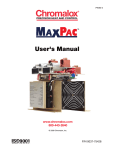
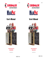
PK480-2
PK480-2
User's Manual
User's Manual
www.chromalox.com
800-443-2640
www.chromalox.com
800-443-2640
© 2014 Chromalox, Inc.
© 2014 Chromalox, Inc.
P/N 0037-75428
P/N 0037-75428
Thank you for choosing the Chromalox® MaxPac™ - a complete power control solution with industry-best
price and performance.
For more than 80 years, customers have relied on Chromalox for the utmost in quality and innovative solutions for industrial heating applications. Chromalox manufactures the world’s largest and broadest line of
electric heat and control products.
The MaxPac Series SCR Controllers provide the best control for applications where consistent heater/process temperature is critical or where fine resolution of power is required.
Common MaxPac features include:
• 120 - 575 Vac @ 100 - 1200 Amps
• Isolated Control Circuit
• Flexible I/O Power Wiring
• Easy Customer Interface
• Remote Shutdown
• Compact Size and Construction
• Touch-Safe Design (option on 100 - 650 Amp models)
• dv/dt Transient Voltage Protection
• MOV Protection
• Built-In Power Distribution
Features for the MaxPac I, II, and III include:
• Zero Crossover Firing
• Isolated Control Circuit
On/Off Control Inputs:
120 thru 240 Vac
5 - 32 Vdc
Dry Contact Closure
Proportional (DOT Firing) Inputs:
4 - 20 mA, 0-5 Vdc, 1 - 5 Vdc, 0 - 10 Vdc
Remote Manual Adjust (Optional)
Remote Auto/Manual Switch (Optional)
• Electronically Protected with Temperature Warning and Shutdown System
• Single- or Three-Cycle Resolution (Jumper Selectable)
• Shorted SCR Detection (Optional)
Features for the MaxPac IP include:
• Phase Angle Firing
• Isolated Control Circuit Inputs
0 - 5 mA, 0 - 20 mA
0 - 50 mA, 1 - 5 mA
4 - 20 mA, 10 - 50 mA
0 - 5 Vdc, 0 - 10 Vdc
• Optional Current Limit
• Soft Start
• Line Voltage Compensation
• Zero & Gain Adjustments
• Built-In Manual Adjustment
• Current Limit Adjustment (Optional)
If you have application questions, refer to the Engineering Resource section of our website at www.chromalox.com to find the answer you’re looking for, or call one of our application
engineers at 1-888-996-9258 for personal assistance.
1-888-996-9258
© 2014 Chromalox®, Inc.
-1-
Table of Contents
SectionTopic
Page
1................................................. Important Safeguards...................................................................................... 3
2................................................. Description...................................................................................................... 4
3................................................. Before You Install............................................................................................. 5
4................................................. Installation....................................................................................................... 6
4.1.................................. Mounting.......................................................................................................... 8
4.2.................................. Wiring............................................................................................................. 11
4.2.1.............. Touch-Safe Design........................................................................................ 11
4.2.2.............. Cover Removal and Installation..................................................................... 12
4.2.3.............. Power/Load Wiring........................................................................................ 12
4.2.4.............. Instrument Power.......................................................................................... 16
4.2.5.............. Grounding...................................................................................................... 16
4.2.6.............. Command Signal Wiring................................................................................ 17
4.2.7.............. Calibration..................................................................................................... 23
5................................................. Specifications................................................................................................ 24
6................................................. Maintenance.................................................................................................. 25
7................................................. Troubleshooting............................................................................................. 26
8................................................. Parts and Accessories................................................................................... 27
9................................................. Warranty and Return Information.................................................................. 28
10............................................... EC Declaration of Conformity........................................................................ 37
-2-
© 2014 Chromalox®, Inc.
1-888-996-9258
1
Important Safeguards
Please read all instructions before installing and operating your MaxPac™.
To avoid electrical shock or injury, always remove power before servicing a circuit.
Personnel working with or near high voltages should be familiar with modern methods of resuscitation. Contact an area supervisor or safety personnel for more information.
Throughout the MaxPac User Manual, the safety alert and the international electric shock/electrocution symbols will alert you to potential hazards. Safety precautions should always be followed to reduce the risk of
personal injury to persons from fire and electrical shock hazards. Safety Alert Symbol
International Shock/Electrocution Symbol
Each safety message is preceded by a safety alert symbol
ING, or CAUTION.
and one of three words: DANGER, WARN-
These mean:
DANGER
You WILL be killed or seriously hurt if you do not follow instructions.
WARNING
You CAN be killed or seriously hurt if you do not follow instructions.
CAUTION
You CAN be hurt if you do not follow instructions.
Damage Prevention Messages:
You will see other IMPORTANT messages that are proceeded by the word CAUTION that are intended
to help prevent damage to the MaxPac™ or other equipment. Note that Damage Prevention Messages are
NOT accompanied by the Safety Alert Symbol.
1-888-996-9258
© 2014 Chromalox®, Inc.
-3-
2
Description
MaxPac I, II, and III
The Chromalox MaxPac I, II, and III controllers are highly versatile SCR Power Paks with optional plug-in
proportional firing and shorted SCR detection boards. Firing modes include On/Off and DOT proportional
zero voltage switching. Chromalox exclusive DOT (Demand Oriented Transfer) firing technique switches the
fewest number of cycles to provide the most precise zero crossover control. At 50% output, the unit’s output
alternates between one cycle “On” and one cycle “Off.” At 51%, the output continues with one cycle “On,” one cycle “Off,” and gradually integrates one extra “On” cycle for the additional 1%. This DOT fired technique also minimizes temperature overshoot, temperature fluctuations and helps extend the load’s element
life due to reduced thermal shock.
The power SCR assemblies consist of one, two, or three pairs of SCRs connected back to back (with an
optional semiconductor fuse), RC Snubber, and MOV protection. The firing circuit is based on a common
On/Off control board with plug and play Shorted SCR and DOT fired plug-in boards. Diagnostic indicators
are included. Plug-in terminal blocks for easy customer interface are also provided.
MaxPac IP
The Chromalox MaxPac IP utilizes Single Phase, Phase Angle firing to modulate power to an inductive or
resistive load. Phase Angle control has the advantage of proportioning every cycle thereby providing very
fine resolution of power. Fast responding loads in which the resistance changes as a function of temperature
require Phase Angle control. The MaxPac IP offers a Soft Start feature that assures that the load power is
gradually increased from zero to the value set by the command signal in the event of a power interruption.
In addition, optional Current Limit is used to protect the load, SCR controller and the total system from large
surge currents that could occur at start-up.
†
This can be set to three cycles ‘On’ / three cycles ‘Off’ (see section on installation options).
-4-
© 2014 Chromalox®, Inc.
1-888-996-9258
3
Before You Install
Immediately after receiving your MaxPac I, II, III or IP Series Controller, visually inspect the shipment packaging and record any damage on the shipping documents. Unpack the controller and carefully inspect for obvious damage due to shipment. If any damage has occurred, YOU must file a claim with the carrier company,
since the carrier company will not accept a claim from the shipper (Chromalox).
Be sure to check the model number and verify that you have received the correct Model of controller.
If the controller is not installed and placed into operation immediately, it should be stored in a cool, dry environment. Temperature extremes and excessive moisture can damage the controller.
Before choosing a location in which to mount your MaxPac, please consider the following:
Temperature
When mounting the SCR unit in a control panel, attention should be paid to the enclosure temperature. The SCR is rated to perform at its nameplate current rating in temperatures up to 50˚C (122˚F).
Ensure that adequate ventilation is provided or some other method of maintaining the correct cabinet temperature is used.
Cleanliness
Careful attention must be paid in areas subjected to airborne particles. The efficiency of the heat
sinks relies on their conducting surfaces being maintained in a clean manner. (See the Maintenance
Section.)
Dampness
High humidity or hosing down a unit should be avoided.
Clearance
Choose a location that will provide adequate spacing around the unit when mounted. This will ensure proper air flow necessary to cool the device.
WARNING
Hazardous Voltage: Disconnect and lockout power before installing or servicing. Failure to comply could result in personal injury
or equipment damage.
1-888-996-9258
© 2014 Chromalox®, Inc.
-5-
InstallationSection
(continuationofpage5)
TheforcedairdesignoftheMaxPacseriesallowsmountinginanydirection.Itisessentialthatairflowthrough
the enclosure be planned to insure proper cooling.
The100ampthrough300ampopendesignMaxPacallowtheinputlinepowertoconnectfromeitheroftwodirections.
The output power can only be connected from one direction. The three mounting configurations
areshownbelow(MaxPacIIThree-PhaseTwo-LegShown).
Opendesignsabove300ampsandallcloseddesignsallowincoming
and outgoing wiring in either direction.
Configuration One
In
CoolAirIn
In
WarmAirOut
Fan
Phase 3
Phase 1
orIn
Out
orIn
Out
Configuration Two
Out
Out
In
In
WarmAirOut
CoolAirIn
Phase 1
Phase 3
orIn
Fan
orIn
Configuration Three
WarmAirOut
Out
Phase 3
orIn
In
Out
Phase 1
In
orIn
Fan
CoolAirIn
-6-
© 2014 Chromalox®, Inc.
1-888-996-9258
InstallationSection
(continuation of page 5)
ExamplesofProperAirFlow
Louvers
Louvers
Air
Fan
MaxPac
Enclosure
Fan
Filter
Forced Air In
Pagoda Top
Fan
Air
MaxPac
Fan
Air
Enclosure
Louvers
Forced Air Out
Since hot air rises naturally, it is not recommended that cooling air enter
from the top and exhaust at the bottom of the enclosure.
1-888-996-9258
© 2014 Chromalox®, Inc.
-7-
4
Installation
Please read all information in this section before beginning the installation of your MaxPac.
Installation of the MaxPac requires three steps:
1.Mounting
2. Power wiring
3. 120 or 230 Vac 50/60hz for instrument power. See 4.2.4, pg. 16.
4.1 - Step 1: Mounting
Before mounting your MaxPac, please read the section titled “Before You Install’ on page 5 for a description
of an ideal environment for the unit’s operation.
The space required for mounting the MaxPac Power Pak depends upon the model. The table below refers to
the figures on the following pages. These figures illustrate the dimensions and mounting holes for the various MaxPac Power Pak models. Please refer to these figures before mounting your unit.
Figure Drawing Number
FigureModel
1................100A, 150A, & 200A 2-Leg Open Type
1................100A, 150A, 200A, & 300A 1-Leg Open Type
2................100A, 150A, & 200A 3-Leg Open Type
3................300A 2-Leg Open Type
4................100A, 150A, 200A, 300A & 400A 1-Leg Touch-Safe
4................400A 1-Leg Open Type
5................100A, 150A, 200A, 300A & 400A 2-Leg Touch-Safe
5................400A 2-Leg Open Type
6................100A, 150A, 200A, 300A & 400A 3-Leg Touch-Safe
6................300A & 400A 3-Leg Open Type
7................550A & 650A 1-Leg Touch-Safe
7................550A & 650A 1-Leg Open Type
8................550A & 650A 2-Leg Touch-Safe
8................550A & 650A 2-Leg Open Type
9................550A & 650A 3-Leg Touch-Safe
9................550A & 650A 3-Leg Open Type
..................800-1200 Amp units, consult factory
Model
IMPORTANT: Please note that the figures on the following pages are
not drawn to the same scale.
-8-
© 2014 Chromalox®, Inc.
1-888-996-9258
4.2" [107mm]
0.0" [0mm]
1.0" [25mm]
Ø0.280" [Ø7.11mm]
(6 HOLES)
4.7" [107mm]
0.0" [0mm]
1.0" [25mm]
Ø0.280" [Ø7.11mm]
(6 HOLES)
FIRING PACKAGE
FIRING PACKAGE
7.2" [184mm]
4.75" [121mm]
8.5" [216mm]
9.5" [241mm]
13.5" [342mm]
14.5" [368mm]
FAN END
6.0" [153mm]
FAN END
6.0" [153mm]
7.3" [185mm]
7.28" [185mm]
Figure 1
Figure 2
5.12" [130mm]
0.0" [0mm]
7.2" [183mm]
1.3" [33mm]
0.0" [0mm]
1.3" [33mm]
Ø0.280" [Ø7.11mm]
(6 HOLES)
FIRING PACKAGE
5.3" [135mm]
FIRING PACKAGE
7.3" [185mm]
13.3" [337mm]
14.6" [371mm]
Ø.3125 [Ø7.94mm]
(8 HOLES)
9.3" [237mm]
13.3" [338mm]
14.6" [371mm]
FAN END
12.0" [305mm]
13.3" [338mm]
Figure 3
FAN END
8.1" [206mm]
9.1" [232mm]
Figure 4
8.4" [214mm]
0.0" [0mm]
1.3" [33mm]
Ø.3125" [Ø7.94mm]
(8 HOLES)
5.3" [135mm]
FIRING PACKAGE
9.3" [237mm]
13.3" [338mm]
14.6" [371mm]
FAN END
14.7" [375mm]
15.75" [400mm]
Figure 5
1-888-996-9258
© 2014 Chromalox®, Inc.
-9-
5.8" [148mm]
11.7" [298mm]
0.0" [0mm]
1.3" [33mm]
0.0" [0mm]
1.3" [33mm]
Ø.3125" [Ø7.94mm]
(8 HOLES)
Ø.3125" [Ø7.94mm]
(8 HOLES)
5.3" [135mm]
6.3" [160mm]
FIRING PACKAGE
FIRING PACKAGE
9.3" [237mm]
11.3" [28mm]
13.31" [338mm]
14.62" [371mm]
16.3" [414mm]
17.6" [448mm]
FAN END
21.4" [543mm]
FAN END
9.5" [241mm]
10.5" [267mm]
22.4" [568mm]
Figure 6
Figure 7
9.8" [249mm]
13.8" [351mm]
0.0" [0mm]
1.3" [33mm]
Ø.3125" [Ø7.94mm]
(8 HOLES)
0.0" [0mm]
1.3" [33mm]
Ø.3125" [Ø7.94mm]
(8 HOLES)
6.3" [160mm]
6.3" [160mm]
FIRING PACKAGE
FIRING PACKAGE
11.3" [287mm]
11.3" [287mm]
16.3" [414mm]
17.6" [448mm]
16.3" [414mm]
17.6" [448mm]
FAN END
17.5" [444mm]
18.5" [470mm]
Figure 8
- 10 -
FAN END
25.5" [648mm]
26.5" [673mm]
Figure 9
© 2014 Chromalox®, Inc.
1-888-996-9258
4.2 - Step 2: Wiring
Careful attention must be paid when attaching the wiring to the MaxPac to ensure proper and safe operation. This section contains detailed information on how to connect the power, resistive load, ground, and
command signal wiring.
WARNING
Hazardous Voltage: Only qualified personnel should perform
electrical wiring for the MaxPac Power Paks. LETHALLY HIGH
VOLTAGES are associated with this equipment and are dangerous if improperly installed.
IMPORTANT: Select installation wiring that is in accordance with the National
Electrical Code and any local standards that may be applicable.
4.2.1 - Touch-Safe Design
If the MaxPac model you purchased is of a Touch-Safe design, follow the steps on the following page to
install the electrical wiring. This will ensure the wiring is done properly while maintaining the Touch-Safe
feature. If your MaxPac is of an Open design below 400 Amps, disregard this subsection.
The following is a detailed drawing of a Touch-Safe unit:
TOUCH-SAFE COVER PROVIDES WIRE ENTRANCE AND
EXIT THROUGH SEALS COVERING THE WIRE WINDOW.
REMOVAL OF THE TAPE BEHIND THE WINDOWS TO
BE USED ALLOWS WIRES TO PASS. THE TAPE
REMAINS ON UNUSED WINDOWS TO PROVIDE TOUCH
SAFE FEATURE.
COVER PROVIDES FOR TOUCH SAFE FEATURE
BUS BAR DESIGN ALLOWS
FOR WIRING FROM EITHER
DIRECTION AND MULTIPLE
LOAD CIRCUITS
BUS BAR DESIGN ALLOWS
FOR WIRING FROM EITHER
DIRECTION AND MULTIPLE
LOAD CIRCUITS
FUSE
COOLING AIR
SCR
HEATSINK FINS
COOLING AIR
LONG LIFE, HIGH OUTPUT BALL
BEARING FANS PROVIDE RELIABLE
COOLING
1-888-996-9258
© 2014 Chromalox®, Inc.
- 11 -
4.2.2 - Steps for Touch-Safe Design Cover Removal and Installation
Remove Cover:
1.
Loosen the thumb screws on both ends of the cover.
2.
Lift the cover from the base.
Install Wiring:
3. 4.
5.
Attach the wires to the bus bars in accordance with the instructions in the next section.
Choose the entrance and exit directions for the wiring as desired. After the wiring is complete, remove the tape from the inside of the wire gaskets of the
windows that the power wiring will enter or exit.
WARNING
Hazardous Voltage: DO NOT remove the tape from the back of
the windows that are not used, as this maintains the Touch-Safe
feature.
Replace Cover:
6.
7.
8.
9.
Angle the end of the cover without screws towards the “fan-end” of the unit.
Slip that end into place first while allowing the wiring to pass through the desired windows.
Slip the opposite end of the cover into place.
Tighten all thumb screws.
4.2.3 - Power/Load Wiring
The following illustrations depict how to connect the MaxPac to a resistive or inductive load. Make sure you
refer to the correct illustration for the MaxPac series you have purchased.
For the power/load drawings:
On open design units up to 300 Amps, X1, X2, X3, L1, L2, and L3 refer to copper lugs.
On open design units 400 Amps and greater and all Touch-Safe designs, X1, X2, X3, L1, L2, and L3 refer
to bus bar connections.
MaxPac I
Single Phase
Resistive
MAX PAC I
X1
L1
L2
L2 Connection is
NOT on MaxPac
- 12 -
© 2014 Chromalox®, Inc.
1-888-996-9258
MaxPac II
Three Wire
2 Leg Control
MAX PAC II
L1
X1
L3
X3
L2
L2 Connection is
NOT on MaxPac
MaxPac III
Four Wire
3 Leg Control
MAX PAC III
L1
X1
L2
X2
L3
X3
N
N Connection is
NOT on MaxPac
CAUTION
IMPORTANT: The I2t fuses installed on the SCR are designed to protect the SCR
from faults on the load connection side. They are NOT intended to provide
wire protection.
1-888-996-9258
© 2014 Chromalox®, Inc.
- 13 -
MaxPac III
Three Wire
3 Leg Control
MAX PAC III
L1
X1
L2
X2
L3
X3
MaxPac IP
Single Phase
transformer
Coupled
MAX PAC IP
X1
L1
L2
L2
L2 connection to
MaxPac is instrument
power only
CAUTION
IMPORTANT: The I2t fuses installed on the SCR are designed to protect the SCR
from faults on the load connection side. They are NOT intended to provide
wire protection.
- 14 -
© 2014 Chromalox®, Inc.
1-888-996-9258
The following drawings show proper installation of the crimp lugs on the bus bars:
Illustration 1: View From Rear Ventilated Panel
LOADBUSBAR
All bolts must mount
with excess bolt lengths
toward the fuse to maintain required electrical
clearances.
FANEND
FUSE
1/0through500mcm
wire must mount on the
fuse side of the bus
bar as shown to
maintain required
electrical clearances
SCR
Smaller wire, #1 through #8, often used
for power distribution, can be connected
tobothsidesoftheloadbus.Wiringmust
be bent slightly to align with the windows
in the top of the touch safe units.
LINEBUSBAR
Illustration 2: View From Top
The bus bars are designed to accept NEMA standard two-hole crimp lugs in accordance with the charts below.
Touch-Safe Units
100 - 400 Amps
Input Bus
Up to (3) 1/0 - 300 mcm (70 mm2 — 150 mm2)
Up to (2) 350 - 500 mcm (185 mm2 — 240 mm2)
Output Bus
Up to (10) #8 - #1 (10 mm2 — 50 mm2)
Up to (3) 1/0 - 300 mcm (70 mm2 — 150 mm2)
Up to (2) 350 - 500 mcm (185 mm2 — 240 mm2)
550 - 650 Amps
Input Bus
Up to (4) 1/0 - 300 mcm (70 mm2 — 150 mm2)
Up to (3) 350 - 500 mcm (185 mm2 — 240 mm2)
Output Bus
Up to (12) #8 - #1 (10 mm2 — 50 mm2)
Up to (4) 1/0 - 300 mcm (70 mm2 — 150 mm2)
Up to (3) 350 - 500 mcm (185 mm2 — 240 mm2)
800 - 1200 Amps Open Design
Input and output bus drilled to accomodate qty (4) 1/0 - 500 mcm NEMA standard two-hole crimp lugs per phase.
1-888-996-9258
© 2014 Chromalox®, Inc.
- 15 -
The power wires must always connect to the fuse side (refer to illustration 1 on page 15) of the bus bar. This
is essential to maintain the required spacing between the phases and sides, and to align with the openings in
the top. The only exception to this is when using power distribution using connectors of sizes #8 to #1. There
is adequate spacing for these connectors to be mounted on both sides of the bus bar, if necessary.
The bolt head should always be on the outside of the bus bar (refer to illustration 2 on page 15) with the bolt
extending towards the fuse.
Flat washers should be used on both the bolt head and the nut, and a lock-washer should be under the
nut.
The Touch-Safe MaxPac is designed to allow both input and output wiring to enter/exit in either direction.
On the 550 Amp and 650 Amp models, it is necessary to mount the wire in the holes that maximize the
distance for the wire to exit the enclosure. This maximizes the distance from the cover to the non-insulated
connector.
When using the power distribution feature and mounting terminals on both sides of the bus bar, the wires
mounted on the outside of the bus bar must be bent inward slightly to align with the opening in the top. All
wiring, especially the larger wires, should be bent prior to mounting to the bus bars. DO NOT use the bus
bars as an anchor to bend the power cables.
4.2.4 - Instrument Power
IMPORTANT
MaxPac requires 120 or 230 Vac 50/60Hz for instrument power. This voltage supplies power for
the control circuits, fans, high temperature warning indicator, and shorted SCR Indicators (see
Fig. 1 on page 21).
This supply is fused on the main circuit board.
4.2.5 - Grounding
Chasis is provided with hole pattern for standard NEMA two-hole crimp lugs.
WARNING
Hazardous Voltage: This Electrical Equipment must be installed by
a qualified person and effectively grounded in accordance to the
National Electric Code and local codes.
- 16 -
© 2014 Chromalox®, Inc.
1-888-996-9258
4.2.6 - Command Signal Wiring
Please refer to the figures on page 19 for illustrations of the 6-, 8-, and 10-pin input terminals.
MaxPac I, II, and III
On/Off Control Signals
AC Input – The 120 thru 230 Vac signal lines are connected to terminal J1 - 7 & 8 (see Fig. 9 on page
21). An input voltage of 120 to 230 Vac turns the power On. The turn OFF voltage is 0 Vac.
DC Input – The 5 - 32 Vdc signal lines are connected to terminal J3 - 1 & 4 (see Fig. 10 on page 21).
An input voltage of 5 to 32 Vdc turns the power On. The turn OFF voltage is 0 Vdc.
Contact Closure Input – The dry contact signal lines are connected to terminal J3 - 1 & 2 (see Fig.
11 on page 21). A closed contact turns the power On. The turn OFF voltage is an open contact.
Process Analog Control Signals
MaxPac I, II, and III have been factory calibrated. These units accept 0 - 5, 1 - 5, 0 - 10 Vdc, and 4 20 mA input signals that are connected to Terminal Block J2. The following signals are connected to:
0 - 5 Vdc: Terminal J2 - 9(+) & 7(-) (see Fig. 7 on page 21)
1 - 5 Vdc: Terminal J2 - 5(+) & 7(-) (see Fig. 5 on page 21)
0 - 10 Vdc: Terminal J2 - 10(+) & 7(-) (see Fig. 8 on page 21)
4 - 20 mA: Terminal J2 - 6(+) & 7(-) (see Fig. 6 on page 21)
Auto/Manual Input
The MaxPac I, II, and III can
be wired to make it possible
to select an input from either a
temperature process controller
or a manual input potentiometer. A switch is used to select
between the input from a 1K
potentiometer and a linear
control input (see Fig. 4 on page
21). The unit is shipped with a
jumper from terminals 2 and 3
of terminal block J2 (see illustration 3). Remove jumper to install
auto/manual input.
CONTACT
NORMALLY CLOSED
(SWNC)
AUTO
HAND
NC
NO
CONTACT
NORMALLY OPEN
(SWNO)
SWITCH
ASSEMBLY
(SW)
PANEL TO BE
MOUNTED TO
LEGEND
PLATE
(LP)
SWITCH KNOB
(SW)
WIRING
1
AUTO
HAND
2
1K
POTENTIOMETER
NC NO
3
4
CW
Illustration 3
CAUTION
IMPORTANT: When enabling the Auto/Manual Input, the jumper from terminals 2
and 3 of terminal block J2 must be removed.
Demand Indicator
The LED demand indicator is located on the main PC board and is viewable through the cover. With
the On/Off control option, the indicator will display steady “on” and steady “off”. With the DOT Firing
option, the indicator will display the rapid firing sequence.
1-888-996-9258
© 2014 Chromalox®, Inc.
- 17 -
SCR Control Board
The Basic control board provides the following functions:
The low voltage dc to operate the circuitry:
A switching regulator circuit converts the instrument power voltage to +12Vdc.
The power distribution for the cooling fans:
The incoming instrument power is fused and then routed to the fan power terminals.
The signal condition for the on/off input and analog inputs:
The 120 to 240 on/off input is isolated by an opto-coupler. The dc and contact
closure inputs are buffered by the circuitry. Amplifiers convert the analog inputs and
the potentiometer input to a signal level compatible with the optional proportional
firing board. The plug-in receptacle for the optional proportional board allows for an
easy upgrade to proportional control.
The drive signal to the SCR trigger boards:
The temperature alarm:
The heat sink temperature is derived from a solid state sensor mounted on the
heat sink. This is then compared to two set points. The first alarm is a warning and
activates the externally connected device. This allows time to correct the problem
before the second alarm inhibits the firing circuit.
The Shorted SCR Alarm:
The plug-in receptacle for the shorted SCR board is located on this board. Signals
from the SCR are routed to the option board. When a short is detected the externally
connected device output is activated.
(
@
(
)
(
)
(
)
)
2AMP(2AG)
CHROMALOXP/N0024-01097
LITTLEFUSEP/N225002
- 18 -
© 2014 Chromalox®, Inc.
1-888-996-9258
Proportional DOT Firing Board
Chromalox’s exclusive DOT (Demand Oriented Transfer) firing technique switches the fewest number
of cycles to provide the most precise zero crossover control. At 50%
output, the unit’s output alternates
between one cycle “On” and one
cycle “Off.” At 51%, the output
continues with one cycle “On,” one
cycle “Off,” and gradually integrates one extra “On” cycle for the
additional 1%.
SHORTJ3-1&2FOR
1CYCLEFIRING
SHORTJ3-2&3FOR
3CYCLEFIRING
Unit shipped for 3 cycle operation
Remote Shutdown
When it is necessary to disable the output, connect a dry contact between J3 - 3 & 4 (see Fig. 12 on
page 21). When it is closed, the power control will shut OFF.
CAUTION
IMPORTANT: This shutdown overrides the control input only. It will NOT protect
against faulted or damaged SCRs.
Shorted SCR Detection (optional)
This option provides a means of alerting an operator to a problem with the system. An external
indicating lamp or relay can be connected to J1 - 5 & 6 (see Fig. 2 on page 21). This indicator must
be rated for the instrument power applied to J1 - 1 & 2. Three diagnostic LEDs show which SCR pair
is faulted. These lights are synchronized with the demand indicator and can only indicate while the
demand is active. Shorting J3 - 5 & 6 can disable the output at J1 - 5 & 6. The alarm can be selected
as latching or non-latching.
A latching alarm means that if the alarm activates and the system subsequently returns to normal,
the alarm will remain latched until a reset button (external switch – customer provided) is pressed. A
non-latching alarm resets automatically.
DEMAND
SHORTEDSCRDETECTION
1
1-888-996-9258
2
© 2014 Chromalox®, Inc.
3
- 19 -
Shorted SCR Detection (optional), cont’d.
The latching and non-latching option is jumper selectable; the jumper is located on the plug-in
shorted SCR detection board. Latching and non-latching operation by the output at J1 - 5 & 6 is
controlled by J3 on the shorted SCR detection board 0135-28096. When this jumper is installed,
latching operation is achieved. The drawing below shows the Shorted SCR Detection board.
UNIT SHIPPED IN NON-LATCHING MODE.
Heat Sink Over-Temperature
An external lamp or relay may be connected to J1 - 3 & 4 (see Fig. 2 on page 21) (this must be rated
for the instrument power applied to J1 - 1 & 2). This will provide an indication to the operator that
the heat sink is approaching an unsafe temperature level. The unit will enter a shutdown mode if the
temperature continues to rise.
- 20 -
© 2014 Chromalox®, Inc.
1-888-996-9258
Input Terminals (MaxPac I, II, and III):
FIG3.
FIG2.
FIG1.
J1
J1
J3
8
7
6
5
4
3
2
1
8
7
6
5
4
3
2
1
6
5
4
3
2
1
120~230INSTRUMENTPOWER
HITEMPINDICATOR.
TheseareACvoltageoutputsat100mAmax.,
not contact closures. See model number
for voltage rating.
SHORTED SCR AND
HI TEMP INDICATORS.
120~230 INSTRUMENT POWER
REQUIRED ON ALL CONFIGURATIONS
FIG5.
FIG4.
J2
1
2
3
4
5
6
7
8
9
10
SHORTEDSCRINDICATOR.
COMMON
AUTO
MANUAL
POTREFVOLTAGE
1K
MANUAL CONTROL INPUT SIG
J2
1
2
3
4
5
6
7
8
9
10
1-5 VDC PROPORTIONAL INPUT SIG
FIG8.
J2
1
2
3
4
5
6
7
8
9
10
J2
1
2
3
4
5
6
7
8
9
10
COMMON
0TO+5VDCPROPORTIONALINPUT
0 TO +5 VDC PROPORTIONAL INPUT SIG
FIG10.
J3
6
5
4
3
2
1
1-5VDCPROPORTIONALINPUT
COMMON
FIG7.
JUMPER
FIG6.
JUMPER
+
+
-
EXTERNAL +5~32 VDC ON/OFF
1-888-996-9258
J2
1
2
3
4
5
6
7
8
9
10
JUMPER
4-20mAPROPORTIONALINPUT
COMMON
4-20mA PROPORTIONAL INPUT SIG
FIG9.
J1
JUMPER
COMMON
8 L1
7 L2
6
5
4
3
2
1
EXTERNAL120~230
ON/OFFCONTROL
0+10VDCPROPORTIONALINPUT
0 +10 VDC PROPORTIONAL INPUT SIG
FIG11.
COMMON
SHORTED SCR INDICATOR RESET.
J3
6
5
4
3
2
1
+
DRY CONTACT ON/OFF
© 2014 Chromalox®, Inc.
120~240 ON/OFF CONTROL
FIG12.
J3
6
5
4
3
2
1
COMMON
REMOTE SHUTDOWN
- 21 -
MaxPac IP
The Chromalox MaxPac IP is a solid-state proportional power controller that utilizes a Phase Angle firing
technique to modulate power to an inductive or resistive load. Separate adjustable Zero, Gain, Manual Bias,
and Current Limit potentiometers are provided along with screw type plug-in connectors for input signals,
Emergency Shutdown, and optional Remote Manual Bias with 0 - 100% dial. All units have thermostat protection with N.C. contacts.
Start-up
The MaxPac IP has been factory calibrated for 4 - 20mA input. Be sure the operating voltage and
signal input are correctly applied. Also, make sure the Emergency Shutdown, if used, has N.O.
contacts and jumper pins 4 & 5 on the 10-pin connector if remote manual bias are not used. Please
read the information on calibration at the end of this section for current limit settings for loads with
extreme hot to cold ratios or those that are overrated. Other ranges may be field calibrated by use
of zero and gain potentiometers.
CAUTION
IMPORTANT: With the Current Limit option, the current transformer must be terminated properly to prevent it from being damaged.
CON1P
TB1
0-5MA
(0-10V)
4-20mA
10-50mA
CT
JB1
JUMPER JB1 FOR 0-5mA
OPEN JB1 FOR 0-10V
L1
FUSE
COM
SCR
CLOSE FOR
REMOTE
SHUTDOWN
X1
L
O
A
D
N/C
N/C
INSTRUMENT
WIRE
L2
JUMPER 4 TO 5
WHEN NOT USING
REMOTE POT
UNIT SHIPPED WITH JUMPER INSTALLED
Customer Connection
- 22 -
© 2014 Chromalox®, Inc.
1-888-996-9258
4.2.6 - Calibration (MaxPac IP):
Many high-temperature heating elements exhibit extreme hot to cold resistance ratios. Heating elements composed of Platinum,
Molybdenum, Tungsten, and Tantalum, to name a few, draw excessive current on start-up. Depending on the mass of the elements,
these “high starting currents” may exist for extended periods of time. Generally, once the elements have achieved their normal operating temperatures, the current drawn through the MaxPac Power Pak will fall within the rating of the unit. For these types of loads, we
recommend adjusting the I LIM (Current Limit) to 50% or less. This will decrease voltage as well as current.
1. Set Current Limit (I LIM) pot to 0% for full current output (CCW).
Current Limit is for limiting current for loads that have
extreme hot to cold resistance ratios or are overrated. We
recommend for these types of loads to adjust I LIM (Current Limit) to 50% or less. This will also decrease voltage
as well as current. 0% Current Limit gives 100% current
output (CCW). 100% Current Limit gives 10% current
output (CW).
7. With power off, connect line voltage and load as shown.
8. Connect meter to input and output.
WARNING: Set meter to correct scale to read proper input or output.
9. Apply power to unit.
10. Adjust input signal to low end of scale.
2. Set Manual (MAN) pot to zero so unit will not be biased above input (CCW).
Manual control adjustment provides a means of setting
the output level of the MaxPac Power Pak in the absence
of controlling instrumentation. The manual control signal
value “adds” to the controlling instrument to set minimum output. The desired output power level may be set
by adjusting the manual control. This value of output will
then be present even in the absence of a control signal.
3. Set Remote Manual pot to zero output so unit will not be biased above input (CCW). (Jumper pins 4 & 5 if not used.)
Remote Manual control adjustment provides a means
of setting the output level of the MaxPac Power Pak in
the absence of controlling instrumentation. The Remote
Manual control is also effective when a control signal
is connected. The Remote Manual control signal value
“adds” to the controlling instrument to set minimum
output. The desired output power level may be set by
adjusting the Remote Manual control. This value of output will then be present even in the absence of a control
signal. Connect Remote Manual pot wire to Pin 4 (CCW),
Pin 5 (W), and Pin 6 (CW) of plug-in connector.
4. Check for open contact for Emergency Shutdown.
Emergency Shutdown inhibits all SCR trigger pulses
regardless of the level of the input signal or manual
potentiometer. For Emergency Shutdown, close contact
Pin 7 to Pin 8 of plug-in connector. Leave contacts open
for operation.
5. Check for polarity of input signal.
6. Adjust input signal to low end of scale.
Zero Adjust control sets the power output starting point
or reference. Thus, it effectively cancels positive inputs
to the MaxPac Power Pak.
EXAMPLE: 0 - 5 mA input à set to 0 mA input
4 - 20 mA input à set to 4 mA input
1-888-996-9258
11. Using the Zero pot, adjust the output voltage just to zero volts.
12. Adjust input signal to top end of scale.
Gain Adjust Control sets the maximum power output for
maximum input signal.
EXAMPLE: 0 - 5 mA input: set to 5 mA input
4 - 20 mA input: set to 20 mA input
13. Using the Gain pot, adjust output voltage just to maximum volts.
14. Repeat steps 11, 12, 13, and 14 until no adjustment is necessary of Zero and Gain pots for proper output voltage
indication. Voltage output should increase proportionally to the signal input applied.
15. Adjust input signal to low end of scale (zero voltage output).
16. With Manual pot at zero for zero voltage output, adjust (CW)
to 100% for full voltage output. Voltage output should increase proportionally. Return to CCW position and output will decrease to zero output.
17. With Remote Manual at zero for zero voltage output, adjust (CW) to 100% for full voltage output. Voltage output should increase proportionally. Return to CCW position and output will decrease to zero output.
18. With Manual pot (CW) at 100% and I LIM (Current Limit) at
0%, adjust I LIM towards 100% noting that voltage
output de
creases with the adjustment of the
Current Limit pot. Adjust Current Limit pot for your
application, if needed.
19. Turn POWER OFF and remove meters. TEST COMPLETE.
© 2014 Chromalox®, Inc.
- 23 -
5
Specifications
MaxPac I, II, and III
Control Inputs
Accepts all of the following as standards:
Resolution (proportional) Better than 0.1%
Line Voltage ....................120 - 575 Vac, 60 Hz
CE 400 Vac 50 Hz
On/Off Control
Signal Input
120 thru 230 Vac ± 10%
5-32 Vdc
Contact Closures
Load Current Rating .......100, 150, 200, 300, 400,
550, 650, 800, 1000, 1200A
Ambient Temperature .....0 - 50°C (32 - 122°F)
Proportional Control
Signal Input Input Impedance
4 - 20 mA.................. 250 Ohms
1 - 5 Vdc................... 10k Ohms or greater
0 - 5 Vdc................... 10k Ohms or greater
0 - 10 Vdc................. 10k Ohms or greater
Optional Remote Manual Adjust
Auto/Manual Switch
SCR Capability
Dielectric ..................Withstand capability
Surge Rating 1500V RMS min.
Typically fifteen (15) times
nominal RMS rating for
8.3 milliseconds
Isolation ......................SCRs isolation 2500V
Input-output isolation 1500V
Instrument Power ....... 120 or 230 Vac
50/60 Hz
Heat Sink .........................Ground potential up to
650 Amps
Output Voltage ............ 0 - 99% RMS line voltage
(Eo=Vsupply - 1.5V SCR
forward drop)
High Temperature ...........AC Voltage Output
Indicator Output
100 mA @ Instrument Power
Shorted SCR ...................AC Voltage Output
Indicator Output
100 mA @ Instrument Power
MaxPac IP
Control Inputs
Accepts all of the following as standards:
Ambient Temperature .....0 - 50°C (32 - 122°F)
SCR Capability ................Withstand capability
1500V RMS min.
Typically fifteen (15) times
nominal RMS rating for
8.3 milliseconds
Phase Angle Control
Signal Input Input Impedance
1 - 5, 0 - 5mA........... 1K Ohms
4 - 20, 0 - 20mA....... 250 Ohms
10 - 50, 0 - 50mA..... 100 Ohms
Surge Rating ...................Typically fifteen (15) times
nominal RMS rating for
8.3 milliseconds
Optional Remote Manual Adjust
Fan Power ................... 120 or 230 VAC
50/60 Hz
Isolation ...........................SCRs isolation 2500V
Input-output isolation 1500V
Output Voltage ............ 0 - 99% RMS line voltage
(Eo=Vsupply - 1.5V SCR
forward drop)
Heat Sink .........................Ground potential up to
650 Amps
Resolution (proportional) Better than 0.1%
Thermostat ......................4 Amps @ 120V resistive
2 Amps @ 240V resistive
N.C. Contact Standard
Line Voltage ................ 120, 208, 240, 277, 380, ...................................... 480 and 575 Vac
± 10% 50/60 Hz
Current Limit ...................10 - 100% of rated
output current
Load Current Rating ... 100, 150, 200, 300, 400,
Soft Start .........................25% demand per second
550, 650, 800, 1000, 1200A typical reset speed
8.3 milliseconds
- 24 -
© 2014 Chromalox®, Inc.
1-888-996-9258
6
Maintenance
WARNING
Hazardous Voltage: Disconnect all power before performing any
maintenance or examining the power module. Exposed terminals
may carry LETHALLY HIGH VOLTAGES when power is applied.
Connections – Loose connections in the power wiring will generate hot spots. These will cause degradation
of electronic equipment. Periodic inspections should be made to ensure that connections are secure and
that there are no signs of excessive heating such as discoloration, and so on.
Corrosion – If the power module is installed in an environment with high humidity or dampness, electrical
connections may suffer corrosion. Periodically check the power module for corrosion.
Damage – Periodically check for rodent damage to wiring and other components.
Filters – Many high-powered control enclosures rely on blowers or fans to maintain a safe operating temperature. The filters used with these devices should be changed on a periodic basis to insure adequate enclosure cooling is maintained.
Dust – Periodically check for dust or other particulate buildup on heatsinks and bus bars.
1-888-996-9258
© 2014 Chromalox®, Inc.
- 25 -
7
Troubleshooting
The following guidelines cover most of the common problems that could occur with the MaxPac. They are
not intended to be, nor can they be, absolutes to cover every possible failure. Problem
No Power or unbalanced power to the load.
If Demand Light is “Off”
1. Check incoming line power.
2. Check the instrument power.
3. Check the fuse on the main board.
4. Verify the input signal.
5. Check that remote shutdown J3 - 3 to 4 is open.
6. Check that the J2 - 2 to 3 is Jumpered.
7. Verify that heat sink is not in over temperature mode by removing temperature sensor plugs from J10, J11, and J12.
If Demand Light is “On”
1. Check the connections to SCR trigger board.
2. Check the power fuses (I2t).
3. Look for damage on the trigger board.
- 26 -
© 2014 Chromalox®, Inc.
1-888-996-9258
8
Parts and Accessories
Instrument Power Fuse
Chromalox Part Number
0024-01097 I2T Fuses for 500 Vac Applications
0024-07634 0024-07630 0024-07632 0024-03116 0024-07633 0024-03118 0024-03200 I2T Fuses for 575 Vac Applications
0024-07644 0024-07645 0024-07636 0024-07637 0024-07638 0024-07639 0024-07640 0024-07646 0024-01191 Fans
Chromalox Part Number
0045-00231 0045-00235 Description
Littlefuse # 225 002 2 AG 2AMP
200 Amp I2t Fuse
250 Amp I2t Fuse
400 Amp I2t Fuse
500 Amp I2t Fuse
700 Amp I2t Fuse
800 Amp I2t Fuse
1000 Amp I2t Fuse
125 Amp I2t Fuse
175 Amp I2t Fuse
250 Amp I2t Fuse
400 Amp I2t Fuse
500 Amp I2t Fuse
700 Amp I2t Fuse
800 Amp I2t Fuse
1000 Amp I2t Fuse
1200 Amp I2t Fuse
Description
120 Vac rated Fan
230 Vac rated Fan
Crimp Lug Chart
For Open Design 400 - 1200 Amp and all Touch-Safe Models:
Conductor Size
Chromalox Part #
#8 AWG (10mm2)
0135 - 10002
#6 AWG or #6 Weld (16mm2)
0135 - 10003
2
#4 AWG or #4 Weld (25mm )
0135 - 10004
2
#2 AWG (35mm )
0135 - 10005
2
#1 AWG or #2 Weld (50mm )
0135 - 10006
#1/0 AWG or #1 Weld (70mm2)
0135 - 10007
#2/0 AWG or #1/0 Weld (70mm2)
0135 - 10008
#3/0 AWG or #2/0 Weld (95mm2)
0135 - 10009
#4/0 AWG or #3/0 Weld (120mm2)
0135 - 10010
250 MCM or #4/0 Weld (150mm2)
0135 - 10011
300 MCM (150mm2)
0135 - 10012
2
350 MCM (185mm )
0135 - 10013
2
400 MCM (240mm )
0135 - 10014
500 MCM (240mm2)
0135 - 10015
Panduit Part #
LCD8 - 14A - L
LCD6 - 14A - L
LCD4 - 14A - L
LCD2 - 56B - Q
LCD1 - 56C - E
LCD1/0 - 12 - X
LCD2/0 - 12 - X
LCD3/0 - 12 - X
LCD4/0 - 12 - X
LCD250 - 12 - X
LCD300 - 12 - X
LCD350 - 12 - 6
LCD400 - 12 - 6
LCD500 - 12 - 6
SCR Replacement
Be sure to replace thermstrate interface material and torque as follows:
MFG Part #
SCR Part #
Thermstrate Part #
Torque inch/lb
to Heat Sink to Terminals
SKKT92
0002 - 47560
0029 - 00700
44 inch/lb (5 Nm)
SKKT162
0002 - 47559
0029 - 00822
44 inch/lb (5 Nm)
SKKT250
0002 - 47537
0029 - 00719
44 inch/lb (5 Nm)
SKKT500
0002 - 47557
0029 - 00814
44 inch/lb (5 Nm)
Torque inch/lb
26 inch/lb(3Nm)
44 inch/lb(5 Nm)
80 inch/lb(9 Nm)
106 inch/lb (12 Nm)
MaxPac I, II, and III
Accessories:
Part Number Description
0135 - 28096 Plug-In Shorted SCR Detection Board
0135 - 28095 Plug-In Proportional DOT-Fired Control Board
0135 - 28093 SCR Trigger Board
0135 - 28094 On/Off Main Firing Board
0135 - 20117 Potentiometer & Remote/Manual Switch
0005 - 60055
0005 - 60057
0005 - 60056
MaxPac IP
Accessories:
Part Number
0135 - 28002
0135 - 28006
0135 - 28037
For CE Application, the Following Filters are Required:
Line Filter Single Phase 230 Vac
Line Filter 120 - 230 Vac 3 Amps
Line Filter Three Phase 440 Vac
Description
Firing Circuit 120, 240 Vac
Firing Circuit 208, 277, 480 Vac
Firing Circuit 380 Vac
1-888-996-9258
© 2014 Chromalox®, Inc.
- 27 -
9
Warranty and Return Information
Warranty Notice
The Warranty below complies with the federal law applicable to products manufactured after December 31,
1976. This warranty gives you specific legal rights and you may also have other rights which vary from state
to state.
Chromalox Warranty
Chromalox instruments and controls are warranted against defects in workmanship and materials. No other
express warranty, written or oral, applies with the exception of a written statement from an officer of Chromalox®, Inc.
Warranty Period
This warranty extends for three years from date of shipment from the factory or authorized distributor.
Limitations
Products must be installed and maintained in accordance with Chromalox instructions. Users are responsible for the suitability of the products to their application. There is no warranty against damage resulting from
corrosion, misapplication, improper specification or other operating conditions beyond our control. Claims
against the carrier company for damage in transit must be filed by the buyer.
Returns
Items returned to Chromalox must be accompanied by a Return Authorization Number. This number may be
obtained from Chromalox’ Customer Service Department at the phone number listed below.
The Return Authorization Number must appear on the exterior of the shipping carton and on the shipping
documents.
Defective items will be repaired or replaced at our option and at no charge.
Return the defective part or product, freight prepaid, to the following address:
Chromalox, Inc.
1347 Heil Quaker Blvd.
LaVergne, TN 37086-3536
Phone: (615) 793-3900
Fax: (615) 793-3563
- 28 -
© 2014 Chromalox®, Inc.
1-888-996-9258
Ordering Information for MaxPac I
Model SCR Power Pack
MXPC I Single Phase SCR Power Pack
Code Control Configuration
1
2
3
4
On/Off Standard (Accepts: 120Vac, 240Vac, 5-32Vdc, Dry Contact Closure)
On/Off Control with Shorted SCR Detection
Proportional Control, DOT Firing (Accepts: 4-20 mA, 1-5 Vdc, 0-5 Vdc, 0-10 Vdc)
Proportional Control, DOT Firing with Shorted SCR Detection
Code Current at 50°C (122°F)
01
02
03
04
100 Amp
100 Amp
150 Amp
150 Amp
Open Design
Touch Safe Design
Open Design
Touch Safe Design
05
06
07
08
200 Amp
200 Amp
300 Amp
300 Amp
Open Design
Touch Safe Design
Open Design
Touch Safe Design
09
10
11
12
400 Amp
400 Amp
550 Amp
550 Amp
Open Design
Touch Safe Design
Open Design
Touch Safe Design
13
14
15
16
17
650 Amp
650 Amp
800 Amp
1000 Amp
1200 Amp
Open Design
Touch Safe Design
Open Design
Open Design
Open Design
Code Line Voltage
1
2
120 Vac - 480Vac
575 Vac
Code Instrument Power
1
2
120 Vac 50/60 Hz
230 Vac 50/60 Hz
Code Compression Lug Kits (Open Design up to 300 Amps)
L0
L1
L2
None
100 - 150 Amp PAK 1(#2 - 4/0)/connection
200 - 300 Amp PAK 1(1/0 - 500mcm)/connection
L1
(Continued on next page)
MXPC I - 2
1-888-996-9258
03
1
1
For Other Ranges See Crimp Lug Chart
© 2014 Chromalox®, Inc.
- 29 -
Ordering Information for MaxPac I (continued)
Code
F00
F01
F02
F03
For < 500Vac Applications, Select One
None
100 -150 Amp PAK (200 Amp Fuse)
200 Amp PAK
(250 Amp Fuse)
300 Amp PAK
(400 Amp Fuse)
F04
F05
F06
F07
400 Amp PAK
550 Amp PAK
650 Amp PAK
800 Amp PAK
(500 Amp Fuse)
(700 Amp Fuse)
(800 Amp Fuse)
(1000 Amp Fuse)
F08
F09
1000 Amp PAK
1200 Amp PAK
(1200 Amp Fuses)
(Two 1000 Amp Fuses)
F10
F11
For 575Vac Applications, Select One(2)
100 Amp PAK
(125 Amp Fuse)
150 Amp PAK
(175 Amp Fuse)
F12
F13
F14
F15
200 Amp PAK
300 Amp PAK
400 Amp PAK
550 Amp PAK
(250 Amp Fuse)
(400 Amp Fuse)
(500 Amp Fuse)
(700 Amp Fuse)
F16
F17
F18
F19
650 Amp PAK
800 Amp PAK
1000 Amp PAK
1200 Amp PAK
(800 Amp Fuse)
(1000 Amp Fuse)
(1200 Amp Fuse)
(Two 1000 Amp Fuses)
Code Remote Man. Adjust/Auto Man. Switch
MXPC I - 2
Fusing Option (1)
03
1
1
L1
F01
0
1
None
Pot with 0 - 100% dial and Local/Remote
Switch(2) Single Turn 1KW Potentiometer
1
Typical Model Number
Crimp Lug Chart
1) SCR Fusing is for semiconductor
protection only, not wire protection. Chromalox # Panduit #
2) Supplied Loose for Customer
0135-10002
LCD8-14A-L
Mounting.
Note:
Storage Temperature 14ºF to 158ºF
(-10ºC to 70ºC).
CE application requires filters.
Chromalox Part Numbers
0005-60055: Line filter, single phase,
230VAC
0005-60057: Line filter, 120-230VAC
0135-10003
0135-10004
0135-10005
0135-10006
0135-10007
0135-10008
0135-10009
0135-10010
0135-10011
0135-10012
0135-10013
0135-10014
0135-10015
LCD6-14A-L
LCD4-14A-L
LCD2-56B-Q
LCD1-56C-E
LCD1/0-12-X
LCD2/0-12-X
LCD3/0-12-X
LCD4/0-12-X
LCD250-12-X
LCD300-12-X
LCD350-12-6
LCD400-12-6
LCD500-12-6
Torque
Conductor Size
In-Lb. Nm
#8 AWG
#6 AWG or #6 Weld
#4 AWG or #4 Weld
#2 AWG
#1 AWG or #2 Weld
#1/0 AWG or #1 Weld
#2/0 AWG or #1/0 Weld
#3/0 AWG or #2/0 Weld
#4/0 AWG or #3/0 Weld
250 MCM or #4/0 Weld
300 MCM
350 MCM
400 MCM
500 MCM
180
180
180
180
180
480
480
480
480
480
480
480
480
480
20
20
20
20
20
54
54
54
54
54
54
54
54
54
Note: NEMA standard two hole copper crimp lugs only.
- 30 -
© 2014 Chromalox®, Inc.
1-888-996-9258
Ordering Information for MaxPac IP
Model SCR Power Pack
MXPC IP Single Phase SCR Power Pack
Code Control Configuration
1
Phase Angle Control
(Accepts: 0-5mA, 0-20mA, 0-50mA, 105mA, 4-20mA, 10-50mA, 0-5 Vdc, 0-10 Vdc)
2
Phase Angle Control with Current Limit
Code
Current at 50°C (122°F)
01
100
Amp Open Design
02
100
Amp Touch Safe Design
03
150
Amp Open Design
04
150
Amp Touch Safe Design
05
200
Amp Open Design
06
200
Amp Touch Safe Design
07
300
Amp Open Design
08
300
Amp Touch Safe Design
09
400
Amp Open Design
10
400
Amp Touch Safe Design
11
550
Amp Open Design
12
550
Amp Touch Safe Design
13
650
Amp Open Design
14
650
Amp Touch Safe Design
15
800
Amp Open Design
16
1000
Amp Open Design
17
1200
Amp Open Design
CodeVoltage
1
120 Vac
2
208 Vac
3
240 Vac
4
277 Vac
5
480 Vac
6
575 Vac
Code Fan Power
1
2
120 Vac 50/60 Hz
230 Vac 50/60 Hz
Code Compression Lug Kits (Open Design up to 300 Amps)
For Other Ranges See Crimp Lug Chart
L0
None
L1
100 - 150 Amp PAK 1(#2 - 4/0)/connection
L2
200 - 300 Amp PAK 1(1/0 - 500mcm)/connection
MXPC IP - 2
1-888-996-9258
03
1
1
L1
(Continued on next page)
© 2014 Chromalox®, Inc.
- 31 -
Ordering Information for MaxPac IP (continued)
Code
F00
F01
F02
F03
For < 500Vac Applications, Select One
None
100 -150 Amp PAK (200 Amp Fuse)
200 Amp PAK
(250 Amp Fuse)
300 Amp PAK
(400 Amp Fuse)
F04
F05
F06
F07
400 Amp PAK
550 Amp PAK
650 Amp PAK
800 Amp PAK
(500 Amp Fuse)
(700 Amp Fuse)
(800 Amp Fuse)
(1000 Amp Fuse)
F08
F09
1000 Amp PAK
1200 Amp PAK
(1200 Amp Fuses)
(Two 1000 Amp Fuses)
F10
F11
For 575Vac Applications, Select One(2)
100 Amp PAK
(125 Amp Fuse)
150 Amp PAK
(175 Amp Fuse)
F12
F13
F14
F15
200 Amp PAK
300 Amp PAK
400 Amp PAK
550 Amp PAK
(250 Amp Fuse)
(400 Amp Fuse)
(500 Amp Fuse)
(700 Amp Fuse)
F16
F17
F18
F19
650 Amp PAK
800 Amp PAK
1000 Amp PAK
1200 Amp PAK
(800 Amp Fuse)
(1000 Amp Fuse)
(1200 Amp Fuse)
(Two 1000 Amp Fuses)
Code Remote Man. Adjust/Auto Man. Switch
MXPC IP -2
Fusing Option (1)
03
1
1
L1
F01
0
1
None
Pot with 0 - 100% dial and Local/Remote
Switch(2) Single Turn 1KW Potentiomete
1
Typical Model Number
Crimp Lug Chart
1) SCR Fusing is for semiconductor
protection only, not wire protection. Chromalox # Panduit #
2) Supplied Loose for Customer
0135-10002
LCD8-14A-L
Mounting.
Note:
Storage Temperature 14ºF to 158ºF
(-10ºC to 70ºC).
CE application requires filters.
Chromalox Part Numbers
0005-60055: Line filter, single phase,
230VAC
0005-60057: Line filter, 120-230VAC
0135-10003
0135-10004
0135-10005
0135-10006
0135-10007
0135-10008
0135-10009
0135-10010
0135-10011
0135-10012
0135-10013
0135-10014
0135-10015
LCD6-14A-L
LCD4-14A-L
LCD2-56B-Q
LCD1-56C-E
LCD1/0-12-X
LCD2/0-12-X
LCD3/0-12-X
LCD4/0-12-X
LCD250-12-X
LCD300-12-X
LCD350-12-6
LCD400-12-6
LCD500-12-6
Torque
Conductor Size
In-Lb. Nm
#8 AWG
#6 AWG or #6 Weld
#4 AWG or #4 Weld
#2 AWG
#1 AWG or #2 Weld
#1/0 AWG or #1 Weld
#2/0 AWG or #1/0 Weld
#3/0 AWG or #2/0 Weld
#4/0 AWG or #3/0 Weld
250 MCM or #4/0 Weld
300 MCM
350 MCM
400 MCM
500 MCM
180
180
180
180
180
480
480
480
480
480
480
480
480
480
20
20
20
20
20
54
54
54
54
54
54
54
54
54
Note: NEMA standard two hole copper crimp lugs only.
- 32 -
© 2014 Chromalox®, Inc.
1-888-996-9258
Ordering Information for MaxPac II
Model SCR Power Pack
MXPC II Three Phase SCR Power Pack
Code Control Configuration
1
2
3
4
On/Off Standard (Accepts: 120Vac, 240Vac, 5-32Vdc, Dry Contact Closure)
On/Off Control with Shorted SCR Detection
Proportional Control, DOT Firing (Accepts: 4-20 mA, 1-5 Vdc, 0-5 Vdc, 0-10 Vdc)
Proportional Control, DOT Firing with Shorted SCR Detection
Code Current at 50°C (122°F)
01
02
03
04
100 Amp
100 Amp
150 Amp
150 Amp
Open Design
Touch Safe Design
Open Design
Touch Safe Design
05
06
07
08
200 Amp
200 Amp
300 Amp
300 Amp
Open Design
Touch Safe Design
Open Design
Touch Safe Design
09
10
11
12
400 Amp
400 Amp
550 Amp
550 Amp
Open Design
Touch Safe Design
Open Design
Touch Safe Design
13
14
15
16
17
650 Amp
650 Amp
800 Amp
1000 Amp
1200 Amp
Open Design
Touch Safe Design
Open Design
Open Design
Open Design
Code Line Voltage
1
2
120 Vac - 480Vac
575 Vac
Code Instrument Power
1
2
120 Vac 50/60 Hz
230 Vac 50/60 Hz
Code Compression Lug Kits (Open Design up to 300 Amps)
L0
L1
L2
None
100 - 150 Amp PAK 1(#2 - 4/0)/connection
200 - 300 Amp PAK 1(1/0 - 500mcm)/connection
L1
(Continued on next page)
MXPC II - 2
1-888-996-9258
03
1
1
For Other Ranges See Crimp Lug Chart
© 2014 Chromalox®, Inc.
- 33 -
Ordering Information for MaxPac II (continued)
Code
F00
F01
F02
F03
For < 500Vac Applications, Select One
None
100 -150 Amp PAK (200 Amp Fuse)
200 Amp PAK
(250 Amp Fuse)
300 Amp PAK
(400 Amp Fuse)
F04
F05
F06
F07
400 Amp PAK
550 Amp PAK
650 Amp PAK
800 Amp PAK
(500 Amp Fuse)
(700 Amp Fuse)
(800 Amp Fuse)
(1000 Amp Fuse)
F08
F09
1000 Amp PAK
1200 Amp PAK
(1200 Amp Fuses)
(Two 1000 Amp Fuses)
F10
F11
For 575Vac Applications, Select One(2)
100 Amp PAK
(125 Amp Fuse)
150 Amp PAK
(175 Amp Fuse)
F12
F13
F14
F15
200 Amp PAK
300 Amp PAK
400 Amp PAK
550 Amp PAK
(250 Amp Fuse)
(400 Amp Fuse)
(500 Amp Fuse)
(700 Amp Fuse)
F16
F17
F18
F19
650 Amp PAK
800 Amp PAK
1000 Amp PAK
1200 Amp PAK
(800 Amp Fuse)
(1000 Amp Fuse)
(1200 Amp Fuse)
(Two 1000 Amp Fuses)
Code Remote Man. Adjust/Auto Man. Switch
MXPC II - 2
Fusing Option (1)
03
1
1
L1
F01
0
1
None
Pot with 0 - 100% dial and Local/Remote
Switch(2) Single Turn 1KW Potentiometer
(Requires Proportional Band)
1
Typical Model Number
Crimp Lug Chart
1) SCR Fusing is for semiconductor
protection only, not wire protection. Chromalox # Panduit #
2) Supplied Loose for Customer
0135-10002
LCD8-14A-L
Mounting.
Note:
Storage Temperature 14ºF to 158ºF
(-10ºC to 70ºC).
CE application requires filters.
Chromalox Part Numbers
0005-60055: Line filter, three phase,
440VAC
0005-60057: Line filter, 120-230VAC
0135-10003
0135-10004
0135-10005
0135-10006
0135-10007
0135-10008
0135-10009
0135-10010
0135-10011
0135-10012
0135-10013
0135-10014
0135-10015
LCD6-14A-L
LCD4-14A-L
LCD2-56B-Q
LCD1-56C-E
LCD1/0-12-X
LCD2/0-12-X
LCD3/0-12-X
LCD4/0-12-X
LCD250-12-X
LCD300-12-X
LCD350-12-6
LCD400-12-6
LCD500-12-6
Torque
Conductor Size
In-Lb. Nm
#8 AWG
#6 AWG or #6 Weld
#4 AWG or #4 Weld
#2 AWG
#1 AWG or #2 Weld
#1/0 AWG or #1 Weld
#2/0 AWG or #1/0 Weld
#3/0 AWG or #2/0 Weld
#4/0 AWG or #3/0 Weld
250 MCM or #4/0 Weld
300 MCM
350 MCM
400 MCM
500 MCM
180
180
180
180
180
480
480
480
480
480
480
480
480
480
20
20
20
20
20
54
54
54
54
54
54
54
54
54
Note: NEMA standard two hole copper crimp lugs only.
- 34 -
© 2014 Chromalox®, Inc.
1-888-996-9258
Ordering Information for MaxPac III
Model SCR Power Pack
MXPC IIIThree Phase Six SCR Power Pack
Code Control Configuration
1
2
3
4
On/Off Standard (Accepts: 120Vac, 240Vac, 5-32Vdc, Dry Contact Closure)
On/Off Control with Shorted SCR Detection
Proportional Control, DOT Firing (Accepts: 4-20 mA, 1-5 Vdc, 0-5 Vdc, 0-10 Vdc)
Proportional Control, DOT Firing with Shorted SCR Detection
Code Current at 50°C (122°F)
01
02
03
04
100 Amp
100 Amp
150 Amp
150 Amp
Open Design
Touch Safe Design
Open Design
Touch Safe Design
05
06
07
08
200 Amp
200 Amp
300 Amp
300 Amp
Open Design
Touch Safe Design
Open Design
Touch Safe Design
09
10
11
12
400 Amp
400 Amp
550 Amp
550 Amp
Open Design
Touch Safe Design
Open Design
Touch Safe Design
13
14
15
16
17
650 Amp
650 Amp
800 Amp
1000 Amp
1200 Amp
Open Design
Touch Safe Design
Open Design
Open Design
Open Design
Code Line Voltage
1
2
120 Vac - 480Vac
575 Vac
Code Instrument Power
1
2
120 Vac 50/60 Hz
230 Vac 50/60 Hz
Code Compression Lug Kits (Open Design up to 300 Amps)
L0
L1
L2
MXPC III - 1
1-888-996-9258
For Other Ranges See Crimp Lug Chart
None
100 - 150 Amp PAK 1(#2 - 4/0)/connection
200 - 300 Amp PAK 1(1/0 - 500mcm)/connection
Note: 550-1200 Amp and all Touch-Safe Designs: Buss
04
1
1
L1
(Continued on next page)
© 2014 Chromalox®, Inc.
- 35 -
Ordering Information for MaxPac III (continued)
Code
F00
F01
F02
F03
For < 500Vac Applications, Select One
None
100 -150 Amp PAK (200 Amp Fuse)
200 Amp PAK
(250 Amp Fuse)
300 Amp PAK
(400 Amp Fuse)
F04
F05
F06
F07
400 Amp PAK
550 Amp PAK
650 Amp PAK
800 Amp PAK
(500 Amp Fuse)
(700 Amp Fuse)
(800 Amp Fuse)
(1000 Amp Fuse)
F08
F09
1000 Amp PAK
1200 Amp PAK
(1200 Amp Fuses)
(Two 1000 Amp Fuses)
F10
F11
For 575Vac Applications, Select One(2)
100 Amp PAK
(125 Amp Fuse)
150 Amp PAK
(175 Amp Fuse)
F12
F13
F14
F15
200 Amp PAK
300 Amp PAK
400 Amp PAK
550 Amp PAK
(250 Amp Fuse)
(400 Amp Fuse)
(500 Amp Fuse)
(700 Amp Fuse)
F16
F17
F18
F19
650 Amp PAK
800 Amp PAK
1000 Amp PAK
1200 Amp PAK
(800 Amp Fuse)
(1000 Amp Fuse)
(1200 Amp Fuse)
(Two 1000 Amp Fuses)
Code Remote Manual Adjust
MXPC III -2
Fusing Option (1)
04
1
1
L1
F02
0
1
None
Pot with 0 - 100% dial and Local/Remote
Switch(2) Single Turn 1KW Potentiometer
(Requires Proportional Band)
1
Typical Model Number
Crimp Lug Chart
1) SCR Fusing is for semiconductor
protection only, not wire protection. Chromalox # Panduit #
2) Supplied Loose for Customer
0135-10002
LCD8-14A-L
Mounting.
Note:
Storage Temperature 14ºF to 158ºF
(-10ºC to 70ºC).
CE application requires filters.
Chromalox Part Numbers
0005-60055: Line filter, three phase,
440VAC
0005-60057: Line filter, 120-230VAC
0135-10003
0135-10004
0135-10005
0135-10006
0135-10007
0135-10008
0135-10009
0135-10010
0135-10011
0135-10012
0135-10013
0135-10014
0135-10015
LCD6-14A-L
LCD4-14A-L
LCD2-56B-Q
LCD1-56C-E
LCD1/0-12-X
LCD2/0-12-X
LCD3/0-12-X
LCD4/0-12-X
LCD250-12-X
LCD300-12-X
LCD350-12-6
LCD400-12-6
LCD500-12-6
Torque
Conductor Size
In-Lb. Nm
#8 AWG
#6 AWG or #6 Weld
#4 AWG or #4 Weld
#2 AWG
#1 AWG or #2 Weld
#1/0 AWG or #1 Weld
#2/0 AWG or #1/0 Weld
#3/0 AWG or #2/0 Weld
#4/0 AWG or #3/0 Weld
250 MCM or #4/0 Weld
300 MCM
350 MCM
400 MCM
500 MCM
180
180
180
180
180
480
480
480
480
480
480
480
480
480
20
20
20
20
20
54
54
54
54
54
54
54
54
54
Note: NEMA standard two hole copper crimp lugs only.
- 36 -
© 2014 Chromalox®, Inc.
1-888-996-9258
EC Declaration of Conformity
We,
Chromalox Precision Heat and Control
1347 Heil Quaker Boulevard
LaVergne, Tennessee 37086-3536
Phone: +1 (615) 793-7561
Fax: +1 (615) 213-8091
declare under sole responsibility that the following described product in our delivered version complies with
the appropriate basic safety and health requirements of the EC Low Voltage Directive (2006/95/EC) and EC
Electromagnetic Compatibility Directive (2004/108/EC) based on its design and type, as brought into circulation by us. In case of alteration of the machine, not agreed upon by us, this declaration will lose its validity.
Description of the Electrical Equipment: MaxPac SCR controllers
Model Number: MaxPac Series; MaxPac I, II, III
Applicable Harmonized Standards:
Low Voltage Directive EMC Directive
Specification: EN60947-4-3:2000
Low-voltage switch gear and
control gear
1. Radiated Disturbance Emissions – 30 to 1000
MHz Electric Field
EN 61000-6-4:2001 / EN 55011:2007
Utilization
Category:
Pollution
Degree 2
Voltage Rating:
Part 4-3: Contactors and
motor-starters
AC semiconductor controllers
and contactors for non-motor loads
AC-51 Non-inductive or slightly
inductive loads, resistive
furnaces
Normally only non-conductive
pollution occurs. Occasionally,
a temporary conductivity
caused by condensation may
be expected.
400 Vac 50 Hz Line
230 Vac 50 Hz Instrument max
75 watts
2. Conducted Disturbance Emissions – Voltage
EN 61000-6-4:2001 / EN 55011:2007
Impulse Rating: 2.5 KV for 5 seconds
Overload
140% for 1 second
Current Profile: Fuses:
500 Volt, 200KA RMS
symmetrical interrupting rating,
I2t fusing provided with all CE
units.
1-888-996-9258
3. Conducted Disturbance Immunity
EN 61000-6-2:2005 / EN 61000-4-6:1996
4. Radiated Disturbance Immunity
EN 61000-6-2:2005 / EN 61000-4-3:1995
5. Electrical Fast Transients/Bursts Immunity
EN 61000-6-2:2005 / EN 61000-4-2:1995
6. Voltage Dips and Interrupts Immunity
EN 61000-6-2:2005 / EN 61000-4-11:1994
7. Electrostatic Discharge Immunity
EN 61000-6-2:2005 / EN 61000-4-2:1995
8. Voltage Fluctuations/Flicker
EN 61000-3-3 / A2:2005
9. Harmonic Current Emissions
EN 61000-3-2:2006
© 2014 Chromalox®, Inc.
- 37 -
Filters Required:
Instrument power filter:
Chromalox P/N 0005-60057
Line Filter, single phase:
Chromalox P/N 0005-60055
Line Filter, three phase:
Chromalox P/N 0005-60056
10. Surge Immunity
EN 61000-6-2:2005 / EN 61000-4-5:1995
The Technical documentation required by Annex IV (3) of the Low Voltage Directive is maintained by (Name)
of (company and location in the European Union)
Year in which CE Marking was affixed: 2002
Authorized Signature/Date: ________________________________________ __________________________
Jim Birnie
Date
Engineering
Manager
Title of Signatory: ________________________________
Chromalox, International
Unit 1.22, Lombard House
2 Purley Way
Croydon CRO 3JP
Surrey
U.K.
- 38 -
© 2014 Chromalox®, Inc.
1-888-996-9258