1
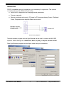
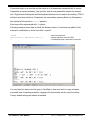
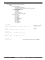
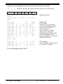
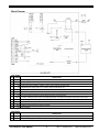
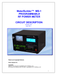
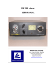
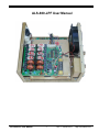
ALS-600-LPF User Manual ALS-600-LPF User Manual 1 Rev. C / 08-Nov-2013 http://www.af6sa.com Introduction ALS-600-LPF kit is a replacement for ALS600FB Output Filter board in Ameritron ALS-600 amplifiers. Features: ✔ Automatic band change based on TX frequency. ✔ Fast and quiet PIN diode QSK RX / TX switch. ✔ Temperature controlled FAN for quiet operation. ✔ Automatic fault recovery. ✔ RS-232 serial port for remote panel, PC control and firmware upgrade. Operation Amplifier’s Standby / Operate mode can be selected with the front panel switch or command thru RS-232 port. Fault recovery is automatic – just release PTT for more than 3 sec and try again. Band Change Amplifier will monitor the exciter transmitting frequency and switch band low-pass filters as needed. Quick and robust algorithm can start band change in less than 2 milliseconds when transmitting in SSB or CW mode. To prevent relays hot switching, power module is disabled during band changes. Optionally, band low-pass filter can be selected from RS-232 port. ALS-600-LPF User Manual 2 Rev. C / 08-Nov-2013 http://www.af6sa.com Fault Conditions and Recovery When a fault condition occurs, the amplifier is bypassed and LOAD FAULT Led will blink a specific pattern to indicate the fault reason. There is no special Operator action required - just release PTT for more than 3 sec and the next start of transmission will try to recover. LED pattern ●○○○●○○○ short blink ●○●○○○ two blinks ●○●○●○●○ fast blink ●○●○●○○○ three blinks ●●●●○○○○ slow blink Status Description message NoPTT PINBias RF input carrier found without asserting PTT while amplifier in OPERATE state. Amplifier is switched temporary in BYPASS until carrier is stopped for >3sec or PTT is activated. PTT line will be disabled when temperature switch is OPEN. Used while tuning antenna. Band filters will be always switched based on measured frequency. PIN diodes bias (300V) was low. Check the 50V / 25A fuse on the back of ALS600PS. SWR Reflected output power above trip point. PASWR PA module reflected power above trip point. OverHeat Temperature is above trip point. OverDrive Forward output power above trip point. Table 1 Notes: ● = LED ON ○ = LED OFF ALS-600-LPF User Manual 3 Rev. C / 08-Nov-2013 http://www.af6sa.com Serial Port RS-232 compatible serial port connection is not mandatory for regular use. This optional connection can provide additional functionality: ✔ Helpful tool for diagnostic and changing internal parameters. ✔ Firmware upgrades. ✔ Remote monitoring and control. LCD panel or PC program showing Output / Reflected Power, Temperature and Amplifier Status can be used. DB9 Male Connector Use NULL modem cable to connect to PC ALS-600-LPF RS-232 Wiring diagram Terminal emulator program such as HyperTeminal can be used to connect with ALS-600 amplifier. Default settings are: 19200 baud, 8bits, no parity, 1 stop bit, no flow control. Start HyperTerminal program and configure a new serial port connection: ALS-600-LPF User Manual 4 Rev. C / 08-Nov-2013 http://www.af6sa.com Commands begin on a new line and can have up to 9 parameters separated with a comma. Parameters in square brackets [ ] are optional, and all next parameters need to be entered. Left / Right arrows, Backspace and Del keyboard buttons can be used for line editing. CTRL-X will abort and clear entire line. Commands are executed by pressing Enter key. Examples in this manual will be printed in italic typeface. Enter key will be represented with symbol. Following example shows how to check the firmware version. Comments are added in this manual for clarification on some lines after < symbol. >ver ALS-600-LPF-1, SN:001001, VER:1.3 > <send command ver <shows response from ALS-600 <if enabled prompt is returned on new line It is very helpful to have a text file open in NotePad or other text editor to copy and paste command lines for backup purposes. Logging to file functionality can be used for backup. Factory default settings are shown in brackets. ALS-600-LPF User Manual 5 Rev. C / 08-Nov-2013 http://www.af6sa.com Fan Display / Set Command Cooling fan speed is regulated by changing the applied voltage from 4V (0%) to 12V (100%). When measured heat sink temperature is below or equal to LowC, fan speed will be set to Low%. When temperature is between LowC and HiC points, fan speed will vary proportionately between Low% and Hi% settings. If temperature is higher than HiC point, fan speed will be set to Hi%. While transmitting, fan speed will be always higher than TX% setting. fan [0..100%] fan [set], [LowC, Low%, HiC, Hi%, TX%] Parameters: LowC Low% HiC Hi% TX% – low temperature point – low fan speed – high temperature point – high fan speed – TXing fan minimum speed –- examples ->fan 37%, T= 32.3C > Factory defaults (30C) (30%) (50C) (100%) (50%) <display fan current speed and amplifier temperature >fan 70 >fan 0 <set speed manually to 70% <resume to automatic fan temperature control >fan set, 30, 40, 80, 100, 70 > <change fan settings >fan set fan set, 30, 40, 80, 100, 70 > <display current fan settings <copy this line and paste it in text editor for backup Use nvmem save command to make any changes permanent. Band Display / Set Command Displays last measured carrier frequency and selected band number. Switch Low-pass filter without sending carrier. band [1..6] –- examples ->band Freq=14176KHz, Band=4 <display measured frequency and LP filter selected > >band 1 <switch to Low-pass filter 1 (160M band) > ALS-600-LPF User Manual 6 Rev. C / 08-Nov-2013 http://www.af6sa.com Baud Rate / Set Command Changes the serial port baud rate immediately. Use nvmem save command to make it permanent. Available serial baud rates are: 9600, 19200, 57600 –- examples ->baud 57600 Switch to 57600 <change your terminal to new baud rate Standby command Turn the amplifier in Standby (bypass) mode. –- examples ->stby > Operate command Turn the amplifier in Operate mode. –- examples ->oper > Note: After power-up Amplifier mode is determined by Standby / Operate switch state. Save to NVMEM / Restore defaults command After power-up the amplifier will read operational and calibration parameters form Non-Volatile Memory (NVMEM) and copies them to RAM. Any changes will modify only the values stored in RAM. Save RAM to NVMEM to make changes permanent. If you want to go back to previously stored values, just restart the amplifier. –- examples ->nvmem save <save all parameters to NVRAM > >nvmem default <restore factory defaults to NVRAM Write Successful! Factory defaults restored! > ALS-600-LPF User Manual 7 Rev. C / 08-Nov-2013 http://www.af6sa.com ADC Display / Calibration Command Three 10bit Analog to Digital converters are used to measure power and protect the amplifier. Output power (FwdV ) and Reflected power (RefV) are measuring the voltage coming from the output RF bridge and peak detectors – same as cross-needle meters. SWRV is measuring the reflected power voltage between PA module and switched Low pass filters. To convert measured voltages to power readings, the firmware uses formula (1): (1) FwdP = ( FwdV * FwdV ) / Fwdcal Calibration of each power reading can be done by adjusting each calibration constant between 1 to 65535. adc [cal], [Fwdcal, Refcal, SWRcal] Parameters: Fwdcal Refcal SWRcal Factory defaults – forward power calibration constant (1100) – reflected power calibration constant (1100) – PA module reflected power calibration constant (5600) –- examples ->adc cal, 1250, 1100, 3000 <set calibration constants > >adc cal <display calibration constants adc cal, 1250, 1100, 3000 <copy this line for backup > >adc <display ADC readings FwdV= 1, RefV= 1, SWRV= 1, TV= 211, PINV= 1 <raw 10bit [0..1023] > >adc FwdV= 826, RefV= 116, SWRV= 463, TV= 220, PINV= 259 <TXing > PINV A/D converter is used internally to generate and regulate the PIN diodes bias voltage. TV A/D converter is sampling the temperature sensor and it is converted to deg. Celsius. Use nvmem save command to make any changes permanent. ALS-600-LPF User Manual 8 Rev. C / 08-Nov-2013 http://www.af6sa.com Fault Trip Point / Set Command Set / display amplifier protection trip points. FwdP and RefP are measured at amplifier output, after peak detectors – same as crossneedle meters. SWRP is measured between PA module and Low pass filters. trip [FwdP, RevP, SWRP, TC] Parameters: FwdP RevP SWR P TC –- examples ->trip 650, 75, 90, 80 > >trip trip 650, 75, 90, 80 Factory defaults – max forward power [100..800W] (650W) – max reflected power [10..100W] (80W) – max reflected power [10..200W] at PA module (160W) – max temperature [0C..90C] (80C) <change trip points settings <display current trip points settings <copy this line and paste it in text editor for backup > Use nvmem save command to make any changes permanent. Status Command Display Amplifier Status word, Forward power, Reflected power, PA module Reflected power and temperature. Information can be displayed continuously 5 times per sec. for monitoring. sta [v], [c] sta d Parameters: v – display status in verbose format . c – display continuously on same line, until CTRL-X is send. d – display line each time Amplifier Status word was changed. ALS-600-LPF User Manual 9 Rev. C / 08-Nov-2013 http://www.af6sa.com Returned Amplifier Status 16bit word description $0fsb - b 4bit selected band: $0-> band is not determent $1->160M, 2->80M, 3->40M, 4-> 20M, 5->15M, 6->10M - s 4bit Amplifier state machine: $0-> Bypassed $1-> Ready $3-> TXing $9-> NoPTTCAR $C..$F-> Fault condition states - f 4bit Fault codes: $0-> no Fault $1-> NoPTT $2-> PINBias $3-> PINBiasRamp $4-> PASWR $5-> SWR $6-> OverDrive $7-> OverHeat –- examples – >sta $0034, FwdP= 614W, RevP= >sta v TXing: 11W, SWRP= 36W, T= 34.6C <display status in HEX <TXing on 20M <verbose FwdP= 621W, SWR= 1.31, T= 34.6C >sta v Standby: FwdP= > 0W, SWR= 1.00, T= 32.3C >sta v Ready: FwdP= > 0W, SWR= 1.00, T= 32.3C >sta v FAULT -> SWR <fault message details can be found in Table 1 > ALS-600-LPF User Manual 10 Rev. C / 08-Nov-2013 http://www.af6sa.com Display a line with debugging information when Amplifier Status was changed. >sta d > Amplifier STATUS - FLAGS <display status, flags, ADC and time elapsed from previous status change ADC FwdV ADC RefV ADC SWRV $0001-0002 1 >sta v Standby: FwdP= >oper 2 1 $0011-000A 1 $0021-0003 1 $0071-0013 26 $0034-0003 734 $0044-0003 657 $0014-0003 645 $0024-0003 1 $0034-0003 707 $05C4-0003 630 $05E4-0003 131 $0514-0003 120 sta v FAULT -> SWR > $0024-0003 1 $0034-0003 813 $0044-0003 681 $0014-0003 668 ADC TV ADC PINV 220 Time elapsed x 0.3mS 1 10925 <Standby on band=1 0W, SWR= 1.00, T= 34.8C 2 2 10 231 192 189 2 364 323 66 60 1 1 994 665 2 1 1 709 675 1 1 222 222 225 223 223 223 224 225 225 225 225 1 1 338 264 262 1 1 333 277 1 1 8880 8826 42 58 31839 64 31891 45 395 9036 301 <operate state <PTT activated <13mS later freq is determined <17mS Txing on band 4 full power <10 sec later PTT released < Ready on band 4 <10 sec later PTT is activated <TXing on band 4 full power <118mS later found SWR is to high <PTT was released for > 3sec <Ready after SWR fault for next PTT <check status verbose 2 44 32 32 1 542 2 1 209 210 209 209 1 326 283 1 10977 45 17651 61 < PTT activated < 13mS Full power TXing on band 4 < 5 sec later PTT released To cancel debugging, press CTRL-X. ALS-600-LPF User Manual 11 Rev. C / 08-Nov-2013 http://www.af6sa.com Block Diagram CN1 Pinout PIN SIGNAL 1 +12V Power supply input +10VDC to +16VDC. Current RX/STBY ~ 0.3A; TX ~ 0.6A Max without Fan. 2 GND Power supply return. Chassis ground. 3 -12V Power supply input -10VDC to -16VDC. Current ~0.01A. Used only by RS-232 port. 4 +5V 5 DESCRIPTION Regulated power supply output. 5V / 0.1A Max. Used for LOAD FAULT Led. -LEDSWR TTL output with 470 Ohm in series. Controls the LOAD FAULT Led mounted on the front panel. 6 OPER 7 PTT 8 BIASP Operate / Standby Input – wired to front panel OPERATE switch. Standby = Open / GND; Operate = wired to +12V PTT Input. Switch to TX when grounded. Wired to PTT jack on the back panel. +12VDC / 0.05A Max. power source for Amplifier Module bias. It is wired to 8V regulator input located on ALC board. 9 GND 10 FWDV Power supply return. Chassis ground. Forward Power Analog input wired to ALC board. 11 REFV Reflected power Analog input wired to ALC board. 12 N.C. Not connected FAN Pinout PIN SIGNAL 1 GND 2 +FAN DESCRIPTION Power supply return. Chassis ground. Fan power supply regulated output +4V up to +12V power supply input less 1.5V drop-out. Current 1A Max. ALS-600-LPF User Manual 12 Rev. C / 08-Nov-2013 http://www.af6sa.com