1
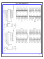
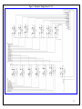
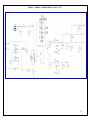
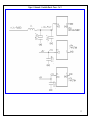
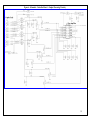
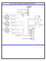
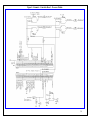
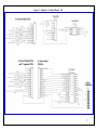
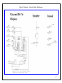
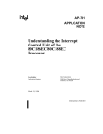
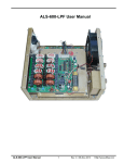
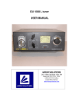
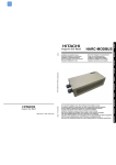
MeterBuilder™ MB-1
PROGRAMMABLE
RF POWER METER
CIRCUIT DESCRIPTION
Version 1.01
June 2011
Patent and Copyright Notices
Patent Applied For
Copyright
Material in this document copyrighted © 2011 FullWave, LLC.
All firmware and software used in the MB-1 copyrighted © 2011 FullWave, LLC.
1
1
CIRCUIT DESCRIPTION ............................................................................................................. 3
1.1
1.2
2
DISPLAY/SWITCH BOARD.......................................................................................................... 3
CONTROLLER BOARD................................................................................................................ 4
SCHEMATICS ................................................................................................................................ 9
FIGURES
Figure 1 – 7 Segment LED - Pin Out .................................................................................. 3
Figure 2 - Schematic - Display Board - 1 of 2 .................................................................. 10
Figure 3 - Schematic - Display Board - 2 of 2 .................................................................. 11
Figure 4 – Schematic - Controller Board – Power – 1 of 2 .............................................. 12
Figure 5 - Schematic - Controller Board – Power – 2 of 2 ............................................... 13
Figure 6 - Schematic - Controller Board – Coupler Processing Circuitry ........................ 14
Figure 7 - Schematic - Controller Board – Panel Meter and Alarm Relay Circuitry ....... 15
Figure 8 - Schematic - Controller Board – Processor Module.......................................... 16
Figure 9 - Schematic - Controller Board – I/O ................................................................. 17
Figure 10 - Schematic - Controller Board – Miscellaneous ............................................. 18
TABLES
Table 1 – Connections Between Display Board and Controller Board .............................. 4
2
1
Circuit Description
1.1 Display/Switch Board
7-Segment LEDS: The internal 7-Segment LEDs are driven from Maxim 7219/7221 ICs.
These chips provide a serial interface that is driven by the PIC processor thereby reducing the
number of interconnect leads between the Display Board and the Controller Board. Each
7219/7221 device drives eight 7-segment LEDs. This chip also controls the brightness of the
7-Segment LEDS. The MB-1 software allows you to adjust the brightness of the 7-Segment
LEDs to one of nine different levels.
The 7-Segment LEDS are plugged in to 40 pin sockets making it easy to swap the LEDs for a
different color. Any .52 inch common cathode 7-Segment LED that has the electrical
footprint below and the pin-out footprint compatible with the 40 pin socket spacing can be
used as long as the current requirement is 20 mA or less per segment. If you obtain your own
7-Segment devices, cut the leads to a length of 3.8 mm if they are longer so that they will fit
properly into the 40 pin sockets.
Figure 1 – 7 Segment LED - Pin Out
Front Panel switches: With the exception of the Power switch and the four menu switches
SWMENU1 - SWMENU4, each of the normally opened contacts of the front panel switches,
when pushed, applies a ground to an input of the I/O expander chip (MCP23S17) on the
Controller Board. The I/O expander chip, in turn, generates a signal that is read by the
processor, which then determines the switch that was pushed and the duration of the push.
The software then takes the appropriate action (such as bringing up a menu on the LCD).
The On/Off Power switch simply applies a closure to the flip flop (HCF-4069 IC) on the
Controller Board to toggle the on/off state of the power relay.
3
Menu Switches SWMENU1 – SWMENU4 are wired directly to the four external interrupt
pins of the PIC processor board. When any of these four menu buttons is pressed, an interrupt
is generated and is immediately processed by the software. This allows most menu selections
to be made without disrupting normal meter operation. Both the Processor interrupt leads
and External I/O chip inputs have internal pull up resistors in the PIC, which eliminates the
need for external pull up resistors.
Each front panel switch contains one or two LEDS that provide status information to the user
(for example, the on/off state of the Panel Meter’s AutoRange feature, or the presence of an
alarm trip condition). All of the switch LEDs, with the exception of the LED on the Power
switch, are driven from output ports from the PIC processor board. The LED on the Power
switch is illuminated directly from the 5 volt bus through a resistor when the Power Relay is
operated.
Interconnection to Controller Board: Three ribbon cable assemblies connect signals
between the Display Board and the Main Controller Board. These cables route the following
signals:
Table 1 – Connections Between Display Board and Controller Board
Connector
Signals
JPWR
5 volts from Controller Board to Display Board
and
Signals to Drive the LEDs on
some of the Front Panel Switches
JLED
Signals to Drive the LEDs on
some of the Front Panel Switches
and
Switch Closure to 4069 Flip Flop Ckt when Power button is pressed
JSW
Signals from the Front Panel Switch Contacts to
the I/O Expander chip, and to the 4 interrupt leads on the Processor Board
1.2
Controller Board
Power: 12 volt DC power is constantly applied from the Power Adaptor to the 4069 IC and
the common terminal of Power Relay RLY1 regardless of the relay’s state. The meter is
protected with a quick blow 1.6 amp fuse.
4
Each press of the power switch on the Display Board toggles the state of the 4069 flip flop.
When the flip flop is toggled on, this turns on transistor Q1, which in turn, operates the
Power Relay RLY1.
The 1000 pf capacitor, which is connected to the 4069 flip flop, is used to force the state of
the flip flop to a predictable (off) condition after a power interruption if the meter was
powered off at the time of the interruption. If the meter is powered on, and a short duration
power interruption occurs (a few seconds), the meter will turn back on with the “Startup Set”
settings when power is restored.
Power relay RLY1 switches the DC 12 volt nominal input voltage to the two 7805 5-volt
regulators. Power is applied through four power diodes (1N540x). These diodes are used as
voltage drop diodes to reduce the heat dissipation of the 7805 regulators. They also provide
polarity protection on the 12 volt input. Because of the current demands of the external
display devices, two regulators are used with each regulator feeding its own power bus.
The +5V bus is used for all of the internal MB-1 circuitry including the PIC processor, the
LCD, and the internal 7-Segment LEDs. The +5V-AUX bus is used primarily for powering
the external 7-segement and external Bar Graph display devices that are provided with the
Expansion Kit. The +5V-AUX bus also powers the alarm relay and sound transducer, and is
also connected to the +5v RCA jacks on the rear panel that are provided for prototyping.
MB-1 can drive larger external 7-segment displays (up to 7 inches high). The 7-segment
displays larger than 1.5 inches are powered from 12 volts instead of 5 volts. Two headers on
the main control board (EXT-7SEG1 and EXT-7SEG2) and associated jumper pins are used
to select the correct voltages for the external display devices (5 volts or 12 volts) based on the
types of external display devices connected to the two Hi-Visibility output connectors on the
rear panel of the meter.
Combinations of 5 volt and 12 volt external 7-segment display devices can be used at the
same time as long as the jumper settings are set properly. The User’s Manual provides
complete details on selecting the proper voltages for the various types of external display
devices. The larger 7-segment displays (greater that 1.5 inches high) are supported only if the
Expansion kit and Large 7-Segment Display option are installed in MB-1.
Note that for reference purposes, the SURE Electronics pin numbering scheme for the 10 pin
IDC connectors (on connectors JHV1 and JHV2) are given in parentheses on both the
schematic and silkscreen on the PCB. This numbering is different than the standard
numbering used for these IDC connectors in the MB-1 documentation. The parenthetical
entries will be useful if you need to cross reference the MB-1 documentation with the SURE
Electronics documentation for any reason.
RF chokes L2 and L3 and associated bypass capacitors provide additional filtering of the
+5V bus. L1 provides filtering for the 12 volt powers that feeds the 4069 flip flop.
Coupler Input Circuitry: Up to four couplers, each with a FWD and REFL signal, may be
connected to the RCA Coupler Port jacks. MB-1 also supports applications other than RF
5
Power measurement. Such applications, referred to as “Generic Meter Applications” in the
MB-1 documentation, allow MB-1 to be interfaced to a wide range of analog sensors. These
applications make use of only the FWD port on the associated coupler input.
The signal from each coupler input port is fed through an RC low pass filter to remove excess
RF or other high frequency noise signals. The signal is then fed into a 15 turn trim pot, which
controls the input level fed into the MCP6S28 multiplexer/amplifier. The MCP6S28 serves
both as a Programmable Amplifier with a maximum gain of 32 and as a multiplexer. After
one of the eight input signals is selected by the multiplexer function, one of six gain settings
is applied, and the amplified signal is routed to the output pin of the MCP6S28. The output
signal is connected to the 10 bit internal A-to-D converter of the PIC Processor on signal
COUP-BUS-FILT after it is further filtered with a two pole low pass RC filter. The gain
factor of the MCP6S28 of 32, together with the 10 bit A-to-D resolution of the PIC processor,
provides an effective low range resolution of 15 bits.
The software controls the gain of the MCP6S28 multiplexer/amplifier device based on the
instantaneous value of the voltage being processed on the coupler FWD and REFL coupler
port leads. The gain is adjusted to maximize the signal that is applied to PIC processor’s Ato-D input without overdriving it. This provides maximum achievable resolution under all
signal conditions.
Panel Meter Drive Circuitry: The internal analog crossneedle Panel Meter and any user
provided external analog meters are driven from dual port 12 bit D-to-A converters
(MCP4922 IC). External Panel Meters are supported only if the Expansion Kit option is
installed.
Using the menu system, each Panel Meter is first calibrated by the user, with the calibration
values being stored in EEProm. Two resistors are connected in series between each D-to-A
output and its corresponding Panel Meter output connection, which terminates on a rear panel
RCA jack. A 100k ohm potentiometer is used for full scale adjustment of the meter
movement, and a 2.7k ohm resistor is used for meter movement protection by limiting the
maximum meter movement current to less than 2 mA regardless of the setting of the panel
meter trim pot.
By setting the Panel Meter trim pot for minimum full scale overshoot during calibration, the
maximum obtainable resolution will be achieved during operation. This will provide
excellent resolution with any analog meter. (If you decide to use the “Soft Overrange” feature
to drive the meter somewhat beyond full scale, this will have a negligible impact on
resolution.)
Alarm Relay: The Alarm Relay RLY2 is tripped when the ALARM feature is enabled and
user defined thresholds are exceeded. In addition to the normal RF power meter trip functions
such as SWR, low power trip, and high power trip, the alarm functions can also be used for
RF ammeter and Generic Meter Applications when MB-1 is used with user-provided analog
sensors.
6
When the software determines that a trip condition has occurred, it applies a logic 1 signal to
lead RLY-ON, which turns on transistor Q2, thereby operating relay RLY2. This relay has
two sets of NO-NC contacts, which are located on the Panel Meter RCA jacks on the rear of
the meter.
Piezo Sounder: The sounder can be used to provide an audible alert when an alarm trip
condition occurs. The sounder can also be configured to provide an enunciator for the push
durations of the front panel switches (short, medium and long presses). The piezo device is
controlled from logic signal SOUND from the PIC processor board, which turns on transistor
Q3, thereby activating the sounder. You can reduce the volume of the sounder by increasing
the value of 47 ohm resistor that is in series with the sounder.
Processor (Daughter Board): The main processor functions are provide by the ET PIC
Stamp daughter board, which contains a high performance PIC18F8722 PIC processor with
128 KB on on-board program memory. This processor also contains 3 KB or RAM, and 1
KB of EEPROM. Because of the sizeable EEPROM requirements for the MB-1 calibration
tables and other configuration settings, one of two external serial EEPROM memory devices,
a 25AA128, or 25AA256 is provided depending upon whether the Expansion Kit is installed.
IC 25AA128 provides an additional 16 KB of EEPROM memory. IC 25AA256 provides an
additional 32 KB of EEPROM memory. The pre-programmed 25AA256 that comes with
the Expansion Kit must be installed to support the External Display modules and external
analog Panel Meters.
A high precision 4.096 volt voltage reference is generated by an MCP1541, which is
connected to voltage reference input VREF on the processor board.
The MCP23S16 16 Bit I/O Expander chip is connected to the processor board through the
SPI serial interface signals SPI-CLK-B, SPI-OUT-B, and SPI-IN. Nine of the 16 ports on
the I/O Expander are used to detect the state of nine of the front panel switches. When any of
these switches is pushed, the generated signal is processed by the I/O Expander chip, which
asserts a logic 0 to the processor board on lead IO-EXT-INT. The software then interrogates
the I/O Expander chip to determine the front panel switch that was pressed and the duration
of the press. (Most front panel switches have multiple functions depending upon the duration
that a switch was pressed.)
MB-1 provides a “push duration” indicator that allows a user to easily determine when the
short, medium, and long push durations of a multi-purpose switch have been reached. The
push duration indicator can be programmed to either flash an LED or to emit a beep at the
transition of each duration. The green LED on front panel switch SW-MENU-DOWN (top
left-most switch) is used for this indicator when an LED indication is selected.
The 80 character LCD is also driven from the processor SPI serial port interface. The critical
serial port signals SPI-OUT and SPI-CLK are buffered through 74HCT08 buffers to reduce
the coupling of noise on to the processor pins.
7
The J45 connector on the processor board is used for factory programming only and is not
used for field operation. The white push button switch on the PIC processor board must be in
the UP position for normal operation and the white jumper pins on the PIC processor board
must be connected as shown in the Assembly Manual.
The processor board also contains a MAX232 Driver/Receiver, which converts the CMOS
levels from the PIC processor to signals that are compatible with driving the RS-232 interface
of a PC serial port. The RS-232 interface is used to communicate with a PC when loading
new firmware into MB-1, when backing up or restoring MB-1’s EEPROM data, or when
updating the preloaded OEM coupler tables in EEProm with new updates issued by
MeterBuilder.
The RS-232 transmit and receive signals are routed from the processor board to the DB9
connector on leads XMT and RCV via the two jumper leads that connect between the PIC
Processor board and two spare connections on one of the 40 pin headers.
Note that the PIC18F8722 has a “Write to Program Memory” instruction that is used by the
bootloader when loading new firmware. Therefore, no special programmer or special voltage
connections are required to update the MB-1 firmware
Front Panel High Precision Potentiometer: - The front panel pot is a 10 turn pot connected
across the 5 volt bus (+5V). The center wiper is connected to lead CALIB-POT, which is
connected to a voltage divider. The tap of this voltage divider feeds one of the processor’s Ato-D inputs on lead CALIB-POT-FILT. The voltage divider drops the maximum voltage
from the potentiometer’s center wiper to a voltage slightly higher than the 4.096 volt
reference used by the PIC’s A-to-D converter. This prevents a dead spot at the top 20% travel
of the high precision pot that would have otherwise resulted.
This high precision pot is used for a number of functions, including Panel Meter Calibration
and “Trim” calibration of the coupler settings. When used for these types of operations, the
front panel pot is used solely during the calibration functions to aid the software in
determining calibration constants that are stored in EEPROM.
The front panel pot is also used to quickly dial in settings when adjusting meter functions
such as the Peak Hold Time. For example, the Peak Hold Time can be easily adjusted from .1
seconds to 9.9 seconds in .1 second increments by dialing in the desired value with the front
panel pot. The high resolution of the 10 turn pot makes it easy to quickly dial in one of these
98 values, which is then saved in EEPROM for later recall. This approach is also used for
several option selections used in the menu and setup screens.
Coupler Trim Pots: Because MB-1 supports a wide variety of coupler types and also
supports interfacing to user-provided analog sensors, each coupler input port will have its
own “full scale” level. The coupler trim pots are used to scale the signal level reaching the
inputs of the MCP6S28 Amplifier/Multiplexer so that maximum resolution can be obtained
without overdriving the input circuitry.
8
Calibration of the MB-1 Coupler using the Trim Pots: All that is required for final
calibration of the included MB-HF1 Coupler is a DC voltmeter and 50 ohm resistive dummy
load. The MB-1 coupler that is supplied with the MB-1 meter has been benchmarked at the
factory and the coupler calibration table has also been preloaded at the factory.
To adjust the coupler trim pot, power is applied from a transmitter though the MB-HF1
coupler into a dummy load. The transmit power is then adjusted until the DC voltage at the
output of the coupler FWD port matches the DC voltage benchmark value printed on the
coupler label. (An RCA Y connector will facilitate this measurement by allowing the voltage
to be measured simultaneously by a multimeter). The coupler trim pot is then simply adjusted
until MB-1 FWD power reading matches the corresponding power level printed on the
coupler’s benchmark label. A similar process can be used to adjust the trim pot for the REFL
coupler port.
2 Schematics
The schematics below have adequate resolution so they can be expanded for easier
viewing.
9
Figure 2 - Schematic - Display Board - 1 of 2
10
Figure 3 - Schematic - Display Board - 2 of 2
11
Figure 4 – Schematic - Controller Board – Power – 1 of 2
12
Figure 5 - Schematic - Controller Board – Power – 2 of 2
13
Figure 6 - Schematic - Controller Board – Coupler Processing Circuitry
14
Figure 7 - Schematic - Controller Board – Panel Meter and Alarm Relay Circuitry
15
Figure 8 - Schematic - Controller Board – Processor Module
16
Figure 9 - Schematic - Controller Board – I/O
17
Figure 10 - Schematic - Controller Board – Miscellaneous
18
Notes
19